Note: Descriptions are shown in the official language in which they were submitted.
21g793~
SPECIFICATION
IC CARD READER/WRITER AND OPERATION METHOD THEREOF
BACKGROUND OF THE INVENTION
1. Field of the Invention
The present invention relates to an IC card
reader/writer equipped with a modem device and used for
an electronic money transaction system. The invention
particularly relates to an IC card reader/writer which is
useful for carrying out the monetary settlement in terms
of electronic money between IC cards which can store
electronic money and also useful as an adapter of a
telephone set, and to a method of operation of the IC card
reader/writer.
2. Description of the Prior Art
In recent years, there has been proposed an
electronic money transaction system for transferring
electronic money based on the communication between IC
cards which can store electronic money. The IC card used
in this system incorporates a microprocessor havin,g a
communication function and a memory, e.g., EEPROM, for
storing aprocessingprogram andthebalanceof electronic
money. The IC card can be used for electronic money
transaction with other IC cards through the electronic
money transaction system which includes terminals
- - 2197933
lnstalledinbanks, retailstores, individual residences,
etc. linked by the public telephone line, or by use o~
dedicated terminals.
The above-mentioned electronic money transaction
system is still at the stage of development, with its
constituent devices being left indeterminate for their
functions and configurations.
SUMMARY OF THE INVENTION
An object of the present invention is to provide an
IC card reader/writer which is useful for the above-
mentioned electronic money transaction system, and is
capableoftransferringelectronicmoneybetweenICcards,
e.g., the person-to-person, person-to-bank and person-
to-retailer transactions, based on the communication
functionoftheassociatedtelephoneset,whileprotecting
the ICcarduserfrom illegal drawoutofelectronicmoney.
Another object of the present invention is to
provide an IC card reader/writer which is capable of
transferringelectronicmoneybetweentwoICcardscoup~ed
to the card reader/writer, or between one or both of two
IC cards coupled to the card reader/writer and other IC
card linked through the telephone line.
Still another object of the present invention is to
provide an IC card reader/writer having card inlets which
2197933
-
allow easy insertion and e~ection of IC cards.
Still another ob~ect of the present invention is to
provide a method of operation of IC card reader/writer
which is useful for the electronic money transaction
system, and is capable of allowlng the user to transfer
electronic money easily and reliably between IC cards,
e.g., the person-to-person, person-to-bank and person-
to-retailer transactions, based on the communication
function of the associated telephone set.
In order to achieve the above ob~ects, the present
inventionresidesinanICcardreader/writerwhichisused
for the electronic money transaction system for
transferring electronic money between IC cards which can
store electronic money, the card reader/writer having at
least one card slot in which one IC card is put in and a
modem device by which the IC card is linked to other IC
card through the telephone line.
Inorderto achievethe aboveob~ects,theinvention
resides in an IC card reader/writer which has at least two
card slots, with one card s~lot being provided insid,e a
cylindrical card holder which is fitted rotatably on the
casing of card reader/writer so that the insertion angle
of the card slot is variable.
Inordertoachievethe aboveob~ects,the invention
resides in an IC card reader/writer which has at least one
21979~3
card slot provided on the front wall or side wall of the
casing of card reader/writer.
In order to achievethe aboveobjects,the invention
resides in an IC cardreader/writer which has aprocessing
functionforelectronicmoneystoredinICcardsandamodem
device for interfacing with the telephone line so that the
card reader/writer is capable of transferring electronic
money between two IC cards put in two card slots or between
one IC card and other IC card linked through the telephone
line.
Inorderto achievethe aboveobjects,theinvention
resides in an IC card reader/writer which serves as an
adapter of a telephone set, the casing of card
reader/writer having a flat top section, and possibly a
slant section joining with the flat section, so that the
telephone set can be placed on the flat top section and
a display window and operation board are arranged in
portions that are not occupied by the telephone set.
In order to achieve the above objective, the
invention resides in a method of operation of an IC card
reader/writer having a modem device which interfaces with
the telephone line so that one IC card which can store
electronic money 1s linked to other IC card of electronic
money through the telephone line, the method comprising
the steps of putting in the IC card in a card slot of the
2~9~933
,
card reader/writer, linking the IC card to the other IC
card through the telephone line, selecting the transfer
direction of electronic money, and entering an amount of
money to be transferred.
BRIEF DESCRIPTION OF THE DRAWINGS
Fig. 1 is a block diagram showing an example of the
organization of the electronic money transaction system
to which the inventive IC card reader/writer is applied;
Fig. 2 is a plan view of the IC card reader/writer
based on an embodiment ofthis invention, with atelephone
set being placed beside it;
Fig. 3 is a perspective view of the IC card
reader/writer of this embodiment;
Figs. 4A, 4B and 4C are a set of diagrams showing
the cross section and installation of the IC card
reader/writer of this embodiment;
Fig. 5 is a block diagram showing the functional
arrangement of the IC card reader/writer with a built-
in modem based on an embodi~ment of this invention; ,
Fig. 6 is a block diagram showing the functional
arrangement of the IC card;
Fig. 7 is a perspective view of the IC card
reader/writer based on another embodiment of this
invention;
2197933
Figs. 8A and 8B are perspective views of the IC card
reader/writer based on still another embodiment of this
invention;
Fig. 9 is a perspective view of the IC card
reader/writer based on an embodiment of this invention,
with a wireless telephone set being integrated with it;
Figs. lOA and lOB are a flowchart explaining the
operational procedure in one case for carrying out the
electronic money transaction between IC card a coupled to
IC card reader/writer A and IC card b coupled to IC card
reader/writer B;
Figs. llA and llB are a flowchart explaining the
operationalprocedurein anothercase forcarryingoutthe
electronic money transaction between IC card a coupled to
IC card reader/writer A and IC card b coupled to IC card
reader/writer B;
Figs. 12A and 12B are a flowchart explaining the
operational procedure in one case for carrying out the
electronic money transaction between IC card a and IC card
b
Figs. 13A and 13B are a flowchart explaining the
operationalprocedureinanothercaseforcarryingoutthe
electronic money transaction between IC card a and IC card
b;
Figs.14 is a diagram showing an example of the key
2197933
layout on the operation board of the IC card reader/writer
based on an embodiment of this invention;
Fig.15 is a diagram showing the wiring of the
inventive IC card reader/writer with a built-in modem and
a usual home telephone set to the telephone line; and
Fig.16 is a flowchart explaining the operational
procedure of carrying out a telephone call to other
telephone subscriber based on a pre-recorded telephone
number read out of the IC card.
DESCRIPTION OF THE PREFERRED EMBODIMENTS
An IC card reader/writer used for the electronic
money transaction system based on an embodiment of this
invention will be explained with reference to the
drawings.
The electronic money transaction system will first
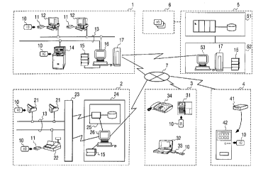
be explained with reference to Fig. 1. In the figure,
reference numeral 1 denotes a bank branch system, 2 is a
retail store system, 3 is an individual user system, 4 is
a vending machine system, 5~is a bank computing cent,er,
6isanelectronicmoneyoriginator,7isapublictelephone
line, 10 is an IC card, 11 is an attached IC card
reader/writer unit, 12 is a banking teller terminal, 13
is an internal communication line, 14 is an auto-teller
machine (ATM), 15 is avalue box, 16 is an electronic money
2197933
_
transaction management terminal, 17 is a relay computer,
21 is an electronic money POS terminal, 22 is a usual POS
terminal,23isastorecontroller,24isacenterfacility,
is a value control/management system, 26 is a
workstation, 31 is an electronic wallet, 32 is a personal
computer, 33 is a PC-attached card reader/writer, 34 is
anICcardtelephone,41isabuilt-inICcardreader/writer,
42 is a vending machine, S1 is a host accounting system,
52 is an external accounting system, and 53 is an external
management terminal.
The electronic money transaction system shown in
Fig.l is made up of a bank branch system 1, retail store
system 2 installed in a large retail dealer such as a
department store or supermarket, individual user system
3 including a personal computer 32 and IC card telephone
34 all linked through a public telephone line 7, and a
vending machine system 4 which is not linked to the
telephone line 7.
Althoughshown inFig. 1 are one setofseveral kinds
of systems,itispossibleto~organize apluralityofth,ese
systems linked through the public telephone line 7. The
bank branch system 1 also has a direct connection through
a leased line to a bank computing center 5, which is
connected to an electronic money originator 6.
IC cards 10, each including a microprocessor with
2197933
a communication function and a memory, e.g., EEPROM, for
storingaprocessingprogram andthebalanceofelectronic
money, are possessed by individual users, banks, retail
stores, vending machines, etc. that are members of the
electronic money transaction system.
The bank branch system 1, which already has the
connection with an existing banking teller terminals 12
and auto-teller machine 14 through an internal
communication line 13, is further connected with the bank
computing center 5 by way of a relay computer 17. For
carrying out the monetary settlement of electronic money,
the banking teller terminals 12 have associated IC card
readertwriter units 11 and the auto-teller machine 14 has
a built-in IC card reader/writer, and these terminals and
machine are connected with a value box 15 by way of an
electronic money transaction control terminal 16.
The bank computing center 5 includes a host
accountingsystem51andan externalaccountingsystem 52,
which includes an external system control terminal 53,
relay computer 17 and value~box 15.
The retail store system 2, with its POS terminals
being generally connected to a center facility 24 through
an internal communication line 13 by way of a store
controller 23, is further provided with IC card
reader/writer units 11 attached to a usual POS terminals
_ 21~79~
22orprovldedwithelectronicmoneyPOSterminals21. The
center facility 24 includes a value control/management
system 25, work station 26 and value box 15.
The user system 3 which mainly supports individual
user,s can be as simple as only an electronic wallet 31 with
the ability of reading out the balance of electronic money
stored in the IC card and possibly with an additional
calculator function. In addition, the user's personal
computer 32 has the provision of a PC-type IC card
reader/writer33forthemonetarysettlementofelectronic
money and the ability of linkage to the public telephone
line 7. The user can also use the IC card telephone 34
which can handle IC cards 10 of electronic money.
The personal computer 32 and IC card telephone 34
of the individual user system 3 have the provision of two
IC card reader/writers so as to perform the electronic
money transfer between two IC cards, and it is possible,
for example, to transfer electronic money from the
husband's IC card to the wife's IC card.
The vending machine system 4 includes a vending
machine 42 having a built-in IC card reader/writer 41.
Next, the method of use of the electronic money
transaction system organized as described above, with the
inventive IC card reader/writer being applied thereto,
will be explained.
21979~3
_
The electronlc money originator 6 distributes IC
cards 10 to banks, retail stores, vending machines and
individual users that are members of the system. Thebank
receives electronic money in exchange for currency, and
stores the electronic money in the value box 15 in the
external accounting system 52. The value box 15 stores
many IC cards, to which electronic money received from the
electronic money originator 6 is distributed and stored.
Electronic money stored in the IC cards in the value box
15 of the external accounting system 52 is distributed to
IC cards in the value box 15 of the bank branch system 1.
Each individual member as a user of the electronic
money transaction system possesses a distributed IC card
10. The user draws one's deposit of bank account in the
form of electronic money and stores it in one's IC card
10 by usingthe bankingteller terminals 12 or auto-teller
machine 14 in the bank branch system 1. The user connects
one's personal computer 32 equipped with the PC-type IC
card reader/writer 33 or one's card telephone 34 to the
bank branch system 1 through~the public telephone lin,e 7
and can convert the deposit account money lnto electronic
money and store it in one's IC card 10.
At the drawing of electronic money, the user's IC
card is linked based on its communication function to a
specific IC card in the value box 15 of the bank branch
- 21979~3
system 1 by way of the banking teller terminal 12,
auto-teller machine 14, personal computer 32, or card
telephone 34. Electronic money stored in the IC card 10
of the value box 15 of the bank branch system 1 is
transferred and stored in the user's IC card 10 under
controlofthetransactionmanagementterminal16. Atthe
same time, the balance of electronic money stored in the
IC card 10 in the value box 15 of the bank branch system
1 is subtracted by the amount of electronic money
transferred to the user's IC card 10. The drawing of
deposits of bank accounts of individuals is the same as
the convention.
It is also possible for the user to convert currency
into electronic money and store it in one's IC card at the
bank or IC card origlnator, instead of drawingthe deposit
of bank account explained above.
Electronic money stored in the user's IC card can
be transferred back to the IC card in the value box 15 of
the bank branch system 1 by way of the banking teller
terminal 12, auto-teller maahine 14 or personal compu,ter
32, and deposited in the user's bank account.
The user having electronic money stored in one's IC
card as explained above can use the IC card to buy goods
and services in retail stores that are members of the
system.
- - 219793~
Specifically, for example, the IC card user who
intends to buy goods brings the things to the POS terminal
counter in the retail store. The clerk operates the POS
terminal 21 or 22 to read the barcode label of each thing
thereby to enter its price and total the prices of all
things, and charges the total price to the customer.
The customer who intends to pay for the goods with
the IC card puts the card into the card inlet of the
electronic money POS terminal 12 or the IC card
reader/writer unit 11 attached to the usual POS terminal
22. The user's IC card is linked to the relevant IC card
in the value box 15 in the center facility 24 of the retail
store by way of the work station 26 over the internal
communication line 13. Electronic money in the user's IC
card is transferred to the IC card in the value box 15 of
the center facility 24, and the POS terminal issues a
receipt to complete the transaction process. Electronic
money in the user's IC card is subtracted by the amount
of payment, and it is added to electronic money in the IC
card of the retail store. ~ ,
Different from the foregolng case of a retail store
having a number of POS terminals and a value box in the
centerfacility24forstoringmanyICcards,asmallretail
shop having only a cash register has the installation of
an IC card reader/writer and has a shop's IC card for the
13
'- 21979~3
cash register, thereby allowing customers to pay with
their IC cards through the linkage to the shop's IC card
bytheICcardreader/writerattachedtothecashregister.
Blectronic money stored in the shop's IC card can be
deposited to the bank account or can also be cashed at the
bank.
As a manner of organizing a retail store system
having POS terminals, these POS terminals are provided
with individual IC cards so that transactions with
customer's IC cards are carried out temporarily based on
the IC cards of POS terminals, and the contents of the IC
cardsaretransferredfromthePOSterminalstotheICcards
in the value box 15 of the center facility 24 afterward
when necessary.
The vending machine 42 included in the electronic
money transaction system is provided with an IC card
reader/writer 41 built in the machine and its own IC card
so that transaction is carried out with a customer's IC
card put in the IC card reader/writer 41 by the customer.
Next, an embodiment of the IC card reader/wri,ter
with a built-in modem used in the foregoing electronic
money transaction system will be explained with reference
to Fig. 2, Fig.3 and Figs. 4A, 4B and 4C showing its
perspective and cross-sectional structure. Throughout
the figures,reference numeral35 denotesatelephone set,
14
21979~3
36 is an IC card reader/writer, 361 is the casing of card
reader/writer, 362 and 363 are card slots, 364 is a card
holder, 365is adisplaywindow, 366 is anoperationboard,
367 is a circuit board.
The IC card reader/writer 36 of this embodiment is
intended to serve as an adapter of the usual telephone set
35, thereby carrying out the electronic money transaction
between two IC cards coupled to this card reader/writer,
or between one IC card coupled to this card reader/writer
and other IC card linked through the telephone line.
As shown in Fig. 2 and Fig.3, the IC card
reader/writer 36 has a display window 365, e.g., liquid
crystal device, and an operation board 366 including a
ten-key set, control keys, etc. all arranged on the top
of the casing 361, and has a card slot 362 for one IC card
10 provided on the front wall and another card slot 363
for another IC card 10' provided on the side wall of the
casing 361.
The casing 361 accommodates a circuit board 367, on
which circuits for the processing of electronic mo,ney
transfer, key operation and information display, and of
the modem for interfacing with the telephone line are
packaged, as shown in Fig. 4A. The IC cards 10 and 10'
are in electrical contact with the circuit board 367 by
means of a contact device (not shown).
21g79~3
The card holder 364 has a cylindrical structure in
which the card slot 363 for the IC card 10' is provided,
and it can be turned to provide a proper card insertion
angle. For example, the cylindrical card holder 364 is
slightly turned counterclockwise on the drawing so that
the user can easily put in the IC card 10' from the front
ascomparedwiththeverticalsettingofthecardslotshown
in Fig.4A.
In another case of the installation of the IC card
reader/writer 36 on the wall as shown in Fig.4B, the card
holder 364 is sllghtly turned clockwise on the drawing so
that the user can easily put in the IC card 10'
oblique-downwardly for example. Shown in Fig.4C is the
caseoftheslantinstallationoftheICcardreader/writer
36 on the wall, with the card holder 364 being turned
properly, so that the user in sitting attitude can easily
put in the IC card 10' vertically or at an arbitrary angle.
The-IC card reader/writer of this embodiment can be
used for transferring electronic money between the user's
IC card 10 and other IC card 10' possessed by one's chi~d,
for example, by putting it in the card reader/writer. It
can also be used for the electronic money transaction
between the user's IC card 10 and other IC card of other
person, bank, etc. (not shown) in a remote place through
the telephone line.
16
- '- 21979g3
For the electronic money transaction through the
telephone line, only one IC card is needed, which is put
in one of the card slots 362 and 363, and electronic money
can be transferred between this card and other IC card
linked through the telephone line. Accordingly, for the
electronic money transaction through the telephone line,
the IC card reader/writer suffices to have only one card
slot, andeven theICcardreader/writer withonlyonecard
slot can attain the objectives of this invention.
Themannerofelectronic moneytransactionproposed
by the inventors of the present invention is described in
detail in Japanese patent publication JP-A-Hei-7-320646.
Next, the internal arrangement of the IC card
reader/writer withabuilt-in modembasedonanembodiment
of this invention will be explained with reference to the
block diagram of Fig.5. In the figure, reference numeral
1104 denotes a loading/unloading circuit, 1105 is a
connector, 1106 is an IC card activation control circuit,
1107isaclockgenerationcircuit,1108isareader/writer,
1109 is a read/write control circuit,lll0 is a ROM, 1~11
is a wavef orm shaping/data extracting circuit, 1112 is
an I/O port, 1113 is a main program ROM, 1114 is a RAM,
1115 is a CPU, 1116 is a card check data memory, 1117 is
a modem interface circuit, and 1118 is a power supply
circuit. The modem interface circuit 1117 is included
17
~1979~3
since the IC card reader/writer of this embodiment is
designedtobeconnectedtothetelephonelineasanadapter
of a usual telephone set.
Namely, the IC card reader/writer 36 of this
embodiment incorporates inside the casing 361 a card slot
362 in which an IC card 10 is put in, a loading/unloading
circuit 1104 which manipulates the IC card 10, a connector
1105 which couples with the IC card 10, an IC card
activation control circuit 11 which supplies the power
voltage and clock signal to the IC card 10, a clock
generationcircuit1107,areader/writer1108whichwrites
and reads data to/from the IC card 10, read/write control
circuit 1109 which controls the operation of the
reader/writer 1108, a ROM 1110 which stores a program run
by the CPU 1115 for implementing the ISO-stated basic IC
card operations, a wave form shaping/data extracting
clrcuit 1111 which shapes the wavef orm of the signal read
out of the IC card 10 and extracts data, an I/O port 1112
which implements data transfer between the reader/writer
1108 andCPU 1115, aROM 1113~which stores the main program
run by the CPU 1115 for the process of electronic money
transfer for the IC card 10, a RAM 1114 used for data
processing by the CPU 1115, a card check data memory 1116
which stores identification (ID) data used for verifying
as to whether the IC card 10 stores electronic money
18
2197~33
information, a modem interface circuit 1117 which
implements the data communication of the card
reader/writer with other IC card through the telephone
line, and a power supply circuit 1118 which distributes
electric power fed in through a connector to the whole
circuitry.
Although the arrangement of Fig. 5 is shown to treat
only one IC card 10, the IC card reader/writer 36 actually
has two sets of loading/unloading circuits 1104,
connectors 1105, reader/writers 1108 and I/O ports 1112,
thereby dealing with two IC cards simultaneously.
The IC card reader/writer 36 of this embodiment
operates as follows. The user puts the IC card 10 into
the card slot 362, and the card is loaded automatically
by the operation of the loading/unloading circuit 1104.
The CPU 1115 detects the IC card 10 in a state of
contact with the connector 1105, and operates on the
control circuit 1106 to supply the power voltage and clock
signaltotheICcardl0. Subsequently,theCPU1115reads
out the ID data from the IC card 10 through the connec,tor
1105 and reader/writer 1108.
These operations are carried out in compliance with
the ISO standard by the program stored in the ROM 1110.
The program includes a format converting routine which
makes the data format match with the IC card protocol, an
19
_ 2197933
IC card activating routine, and a card reading/writing
routine.
The CPU 1115 compares the ID data read out of the
IC card 10 with the record in the card check data memory
1116 thereby to verify the electronic money information
in the IC card 10. Upon certifyingthe information stored
in the IC card 10, the IC card reader/writer 36 is ready
to run the main program of electronic money processing
stored in the ROM 1113. The foregoing operations take
place automatically regardless of the operational state
of other IC card handling apparatus which is linked to the
IC card reader/writer 36 through the telephone line.
Fig. 6 shows the internal arrangement of the IC card
10 of electronic money. In the figure, reference numeral
103denotesacontactdevice,104isaCPU,105isanEEPROM,
and 106 is a ROM.
Namely, the IC card 10 has a contact device 103 for
thecommunicationofthepowervoltageandtheclock,reset,
data and other signals with the circuitry of card
reader/writer, and incorporates a CPU 104 which contr~ls
the operation of the card, a re-writable EEPROM 105 which
memorizes data of electronic money, etc., and a ROM 106
which stores a program of the card.
The CPU 104 implements the data input/output
protocol in compliance with the ISO standard and the
219~g33
encryption process based on the program in the ROM 106.
Electronic money information and transaction history
information are memorized in the EEPROM 105.
The IC card reader/writer 36 of this embodiment has
its basic operation carriedout by the main program stored
in the ROM 1113 which is accommodated in the casing 361
ofcardreader/writer36. Basedontheconfinementwithin
the IC card reader/writer of the function of access to
electronic money in the IC card 10, the security against
incorrect operations on the IC card and illegal access to
electronic money in it can be enhanced.
Fig. 7 shows a different external structure of the
inventive IC card reader/writer. This IC card
reader/writer has a liquid crystal display window 368
which takes up the entire top surface of the casing 361.
The display window 368 displays information, and also
displays the keytops of a ten-key set and function keys,
thereby functioning as a touch-panel operation board.
Thisstructureprovidestheenhancedvisibilityofdisplay
and operability of the IC card reader/writer.
Figs. 8A and 8B show still another external
structure of the inventive IC card reader/writer. This
IC card reader/writer ls designed to place a usual
telephone set 35 atop the casing as shown in Fig.8A.
Specifically, the casing 361 has a flat top section 361'
21
219793~
which is wide enough to place the telephone set and a slant
section 361" which ~oins wlth the top section, with the
display window 365 and operation board 366 being arranged
in the slant section, as shown in Fig. 8B. This IC card
reader/writerhasathirdcardslot362'formedinthefront
wall of the casing 361.
One or both of the two front card slots 362 and 362'
are used. For example, one IC card 10 is used for the
transaction of electronicmoney, while anotherIC cardl0"
is used for recording the history of transactions of
householdaffairs. Alternatively,twoICcardsl0andl0'
of electronic money are used simultaneously for a large
amount transaction with a bank or retail store in excess
of the storage capacity of one IC card.
This IC card reader/writer is also capable of
transferring electronic money between one of IC cards 10
and 10" put in the front card slots and another IC card
10' put in the rear card slot 363.
Instead of forming the card slots 262 and 262' in
the front wall of the casing 361 as shown in Figs.8A ,and
8B,theinventiveICcardreader/writercanhavethesecard
slots formed in the side wall of the casing 361, and they
can be used in the same manner as the former case.
Fig. 9 shows the IC card reader/writer based on
another embodiment of this invention, which is integrated
21979~3
withawirelesstelephoneset. ThisICcardreader/writer
is integratedwith aportable wirelesstelephoneset which
is prevailing recently, allowing the user to carry out the
card-based transaction in any place.
In addition to the convenient use by individual
usersathomeoftheICcardreader/writersoftheforegoing
embodiments, they can be installed in a small-size retail
shop or can be attached to a conventional POS terminal in
a large or medium-size retail store so that customers can
pay for commodities in terms of electronic money.
The IC card reader/writers of the foregoing
embodiments of this invention, which have the card slots
of easy insertion and e~ection of IC cards and can be used
with a telephone set, enable the transfer of electronic
money between IC cards, e.g., the person-to-person,
person-to-bank and person-to-retailer transactions,
based on the communication function of the associated
telephone set, while protecting the IC card user from
illegal draw out of electronic money.
Next, the operational method of IC card
reader/writer based on an embodiment of this invention
will be explained.
Figs.lOA , lOB and Figs.llA and llB show one
operational procedure of electronic money transaction
between IC card a coupled to IC card reader/writer A and
2197933
ICcardbcoupledtoICcardreader/writerBwhichislinked
to the card reader/writer A. Figs.12A,12B and
Figs.13A,13B show another operational procedure of
electronic money transaction between IC cards a and b
coupled to the linked IC card reader/writers A and B.
Fig. 14 shows an example of the key layout on the
operation board 366 of an IC card reader/writer based on
an embodiment of this invention. Among the keys on the
operation board 366, Balance key 1401 is used to read out
the balance of electronic money in the immediate IC card,
History key 1402 is used to display the history of
electronic money transactions which have been carried out
with the card, Money Type key 1403 is used to select a kind
of money of transaction in case the IC card can treat more
than one kind of money, Card Select key 1404 is used to
designate one of IC cards in the card slots 362 and 363
and other IC card linked through the telephone line, a
lock/unlock key 1405 is used to lockor unlock the IC card,
Transfer key 1406 is used to transfer electronic money
between IC cards on the card reader/writer, another
Transferkey1407isusedtotransferelectronicmoneyfrom
the immediate IC card to other IC card linked through the
telephone line, still another Transfer key 1408 is used
to transfer electronic money from other IC card linked
through the telephone line to the immediate IC card, Clear
24
2197933
1409 is used to cancel the keyed-in data or terminate the
operation, Menu key 1410 is used to select an operational
mode, Cursor-Up/Down keys 1411 and 1412 are used to move
the cursor of the display window 365 or select an IC card,
Enter key 1413 is used to establish the keyed-in data or
proceed to the action, a ten-key set 1414 is used to key
innumeralsfortheentry of an amountofmoney orthe like,
and Star key and Sharp key 1415 and 1416 are used for mode
selection and the like.
Fig. 15 shows the wiring of the inventive IC card
reader/writer 1502 with a built-in modem and a usual home
telephone set 1501, which is connected to the telephone
line 1503 by way of the card reader/writer 1502. Based
on this wiring, electronic money transaction is carried
outbetweentheICcardcoupledtotheICcardreader/writer
1502 and other IC card linked through the telephone line.
The operational procedure of sending electronic
money from IC card a on the IC card reader/writer A to IC
card b on the IC card reader/writer B which is linked to
the card reader/writer A thr~ough the telephone line will
be explained on the flowchart of Figs.lOA and lOB. This
isthecasewheretheamountofmoneytransferisdetermined
mainly by the sending party, e.g., for money transfer from
a parent to one's child.
Initially, theuserputs the ICcardintotheIC card
- 2197933
reader/writer A (will be called simply "device A"):(step
1001), and pushes Transfer key 1406:(step 1002). The
device proceeds to the initial mode of money transfer
between two IC cards on the device A, with a sign being
displayed as shown by 1003.
The user, who intends to have an electronic money
transaction with IC card b linked through the telephone
line, pushes Star key 1415:(step 1004). In this
embodiment, the device is designed to switch to the mode
of electronic money transaction over the telephone line
in response to the operation of Star key 1415. The user
next pushesCardSelect key 1404 (step 1005), andthen uses
Up key 1411 or Down key 1412 to select the transfer
direction:(step 1006).
A sign of the money transfer direction is displayed
by being switched in response to the operation of the Up
key 1411 and Down key 1412 as shown by 1007. Among the
signs displayed at this stage, "Card l" indicates the
lower IC card in the front card slot 362, "Card ~ "
indicates the upper IC card ln the rear card slot 363, and
"Remote"indicatestheexternalICcardlinkedthroughthe
telephone line. With the sign of intended transfer
direction being displayed, i.e., as shown by 1009 in this
example, the user pushes Enter key 1413 to determine the
moneytransferdirection:(step1008). Theoperations and
'_ 2197933
sign displays up to this stage are also relevant to the
receiving IC card reader/writer B (will be called simply
"device B") as shown by steps 1001'-1009'.
Subsequently, the user of the sending device A
enters an amount of money to be transferred (step 1010),
andupon confirmingthekeyed-in amount displayedasshown
by 1011 (step 1012), the user pushes Enter key 1413:(step
1013). This sending user's operation for money transfer
is validated in response to the pushing of Enter key on
the receiving device B within a prescribed time
length:(step 1013'). The operational procedure of
needingtheconfirmationbyboth thesendingandreceiving
users enhances the security of electronic money transfer.
Following the normal confirming operations of steps 1013
and 1013' by both users, the outgoing and incoming of
electronic money take place (steps 1014 and 1014'), with
displays being presented during the transfer process as
shown by 1015 and 1015'.
On completion of money sending (step 1016) and
reception (step 1016'), the devices A and B have displ~ys
on their display windows as shown by 1017 and 1017'. In
this example, ~3000 of electronic money has been
transferred from IC card a to IC card b.
Next, the operational procedure of receiving
electronicmoneyintoICcardaontheICcardreader/writer
27
21g79~3
'--
A from IC card b on the IC card reader/writer B which is
linked to the card reader/writer A through the telephone
line will be explained on the flowchart of Figs.llA and
llB. This is the case where the amount of money transfer
is determined mainly by the receiving party, e.g., money
reception by a mail-order retailer from a customer who has
bought commodities.
In the figure, operations and displays 1701-1717 on
the part of the device A and operations and displays
1701'-1717' on the part of the device B are identical to
those 1001-1017 and 1001'-1017', respectively, shown in
Fig.10. The procedure of Figs.llA and llB is different
fromFigs.lOAandlOBinthattheuserofthesendingdevice
B has operations (steps 1718'-1720') of confirming the
amount of money to be sent which has been determined and
entered by the user of the receiving device A.
Following the entry of money amount to be received
on the device A andthe operations on both devices in steps
1713 and 1713', a sign of prompting the confirmation of
the amount is displayedonthe displaywindowofthe device
B as shown by 1719'. In response to the pushing of Enter
key 1413 (step 1720') by the user of device B upon
confirmingthemoney amount(step 1718'),theoutgoingand
incoming of electronic money take place:(steps 1714 and
1714'). In this example, ~3000 of electronic money is
~ 21979~3
transferred from IC card b to IC card a.
Next, another operational procedure of sending
electronic money from IC card a on the device A to IC card
b on the device B which is linked through the telephone
line, as in the case of the preceding example of Figs.lOA
and lOB, will be explained on the flowchart of Figs.12A
and 12B. This is the same case where the amount of money
transfer is determined mainly by the sending party, e.g.,
for money transfer from a parent to one's child.
Initially, the user of the device A puts the IC card
into the card slot 362 or 363 (step 1201), and pushes
Transferkey1406:(step1202). Thedeviceproceedstothe
initial mode of money transfer from the IC card on the
device A to the IC card on the device B. The device A
detects automatically the number of IC cards put in
it:(step 1203).
In case more than one IC card are detected, the user
isrequiredtoselectacardasthesendingcard:(step1204).
In the case of a single card put in the device or following
the selection of sending cardin step 1204, a sign of mo~ey
transfer direction is displayed on the display window 365
of the device A as shown by 1206:(step 1205).
Subsequently, the user enters an amount of money to
besent:(step1207),andadisplayasshownby1208appears.
Upon confirming the keyed-in amount (step 1209), the user
29
2197933
pushes Enter key 1413:(step 1210). The device A
remote-controls the device B over the telephone line,
thereby performing the money transfer from it and money
reception on the device B (steps 1211 and 1211'), with
displays being presented on the devices A and B as shown
by 1212 and1212',respectively, duringthemoneytransfer
process.
On completion of money sending by the device A (step
1213'), it has adisplayasshownby1214', andoncompletion
of money reception by the device B (step 1213'), it has
a display as shown by 1214'. In this example, Y3000 of
electronic money has been transferred from IC card a to
IC card b. According to the operational manner shown in
Figs.12A and 12B, the user of the receiving device B is
simply required to put in the IC card (step 1201'), and
can receive electronic money by the automatic operation
on the side of the sending device A.
Next, another operational procedure of receiving
electronic money into IC card a on the device A from IC
cardbonthedeviceBwhichislinkedthroughtheteleph,one
line, as in the case of the preceding example of Figs.llA
and llB, will be explained on the flowchart of Figs.13A
and 13B. This is the same case where the amount of money
transfer i9 determinedmainlybythereceivingparty,e.g.,
money reception by a mail-order retailer from a customer
-. _ 2197933
who has bought commodities.
In the figures, operations and displays 1301-1314
on the part of the device A and operations and displays
1301'-1314' on the part of the device B are identical to
those 1201-1214 and 1201'-1014', respectively, shown in
Figs.12A and 12B. The procedure of Figs.13A and 13B is
different from Figs.12A and 12B in that the user of the
sending device B has operations (1315'-1317') of
confirming the amount of money to be sent which has been
determined and entered by the user of the receiving device
A.
Following the entry of money amount to be received,
the device A remote-controls the device B over the
telephone line to display a sign of prompting the
confirmation of the amount on the display window of the
device B as shown by 1316'. In response to the pushing
of Enter key 1413 (step 1317') by the user of device B upon
confirmingthemoney amount(step 1315'),theoutgoing and
incoming of electronic money take place:(steps 1311 and
1311'). In this example, ~3000 of electronic money,is
transferred from IC card b to IC card a.
Fig.16 shows the operational procedure of carrying
out a telephone call to other telephone subscriber based
on apre-recordedtelephonenumberreadoutoftheIC card.
Initially, the user puts the IC card having a record
21~7933
of telephone numbers into the card slot 362 or 363:(step
1601). The user pushes Menu key 1410 (step 1602) to have
the operation menu displayed. The user uses Up key 1411
or Down key 1412 (step 1603) to point the intended label
"TEL.CODE LIST" with the cursor:(step 1604).
The user checks the menu selection pointed by the
cursor, andpushes Enter key 1413:(step 1605), then a list
of telephone numbers is displayed:(step 1606). The user
uses Up key 1411 or Down key 1412 (step 1607) to point an
intended telephone number with the cursor:(step 1608).
Finally, the user pushes Enter key 1413 (step 1609), and
the IC card reader/writer 1502 with a built-in modem
operates to dial the specified telephone number
automatically:(step 1610).
When the user takes up the handset of the telephone
set 1501 (step 1611), the modem device switches the
connection of telephone line from the card reader/writer
1502 to the telephone set 1501 automatically (step 1612),
allowing the user to use the telephone set as usual.
This operational method eliminates the need,of
dialing a telephone number with the ten-key set 1414, and
the telephone calling operation is simplified. This
function further facilitates the electronic money
transaction through the telephone line. In addition, in
the event of failure of the telephone set, data recorded
32
- 2~g79~3
in the IC card can be used intact on a replaced telephone
set, in contrast to the conventional telephone set with
a data memory, in which case the user is obliged to record
a list of telephone numbers or the like all over again in
a replaced telephone set.
According to the present invention as described
above, it becomes possible to transfer electronic money
between IC cards, e.g., the person-to-person, person-
to-bank andperson-to-retailer transactions, basedonthe
communication function of the associated telephone set,
while protecting the IC card user from illegal draw out
of electronic money.
The inventiveIC cardreader/writerfacilitates the
insertion andejectionofICcardsbasedon itsuniquecard
slots. The inventive operation method of IC card
reader/writer facilitates the electronic money
transaction through the telephone line.