Note: Descriptions are shown in the official language in which they were submitted.
219 8 tl ~'~
IbIPROVED ENDLESS TRACK UNIT k~OR FOUR-TRAG~CED VEFIICLES
FIELD OF THE INVENTION
The present invention relates to all-terrain
tracked vehicles, and more particularly to an improved
endless track unit for four-track tracked vehicles.
LO BACKGROUND OF T8E INVENTIOid
Endless track-driven vehicles are commonly
used off-road in difficult terrain and under difficult
terrain conditions such as in mud, snow, sand and
tundra. ~'or example, tracked vehicles axe used in snow
25 country for grooming ski slopes and snowmobile trails,
for transporting skiers to back country.slopes, for ski
resort maintenance work, for snow and mountain rescue
and for utility company maintenance work.
Tracked vehicles are generally of two types.
ZO Moet tracked vehicles are of the two-track type, in
which a pair of endless track units, one on each of the
opposite sides of the vehicle, support and drive the
vehicle. The other type is the four-track, in which
four separately driven and independently suspended
25 track units, two in front and two in the rear, support
and drive the vehicle.
Four-track vehicles have certain advantages
over two-track vehicles under extreme conditions such
as on steep slopes and in very rough terrain because of
30 the flexible independent suspension of the four-track
units and the constant power available to all four-
track units, even while turning. Unlike a two-track
veh~.cle, which relies on the differential speed of the
two tracks for turning, the four-track vehicle steers
35 much like a wheeled vehicle. xts endless track unite
can be physically turned for steering.
Despite the advantages of four-track vehicles
over two-track vehicles under extreme terrain
conditions, the nature of four-track vehicles is such
- 1 -
2198957
that there are several inherent problems with the
existing designs.
First, there is an inherent problem in
transmitting power to the tracks of the four txack
units. This problem arises because each track must be
driven by a single drive wheel having a sprocket with
teeth for drivingly engaging the track. The drive
wheel receives power from the vehicle engine through a
dxive train that includes two differentials and four
Zo axle assemblies. The nature of the drive train and
xequired vehicle ground clearance dictates that the
drive wheel of each track unit be located at the apex
of a generally triangular track configuration. All
other track-supporting wheels of each track unit are
idlers, i.e., undriven guide wheels. These guide
wheels are spaced apart along the base of the
triangular track unit from end to end thereof.
Ideally, the track that is trained about the
drive wheel and guide wheels should be absolutely taut
and, therefore, incapable of movement from its pitch
line in a direction normal to the direction of the
track run, i.e., the path of travel of the track about
the drive sprocket and guide wheels. However, the
known drive wheels often contribute to the track
deviating from this ideal path.
mown drive wheels drivingly engage the track
with two of fewer sprocket teeth. For example, the
inventions in U.S. Pat. 3,787,099 and U.S. Pat.
3,857,616, issued January 22, 1974 and December 31,
1974, respectively, disclose using a seven tooth drive
wheel: however, as best shown in FIG. 4 of each of
those references, only two teeth ever drivingly engage
the drive saddles of the track at any given time. With
this limited interaction between the drive wheel and
track, several problems arise.
For example, the known interaction of the
track with the drive wheel on four track vehicles
- 2 -
2198057
subjects the track to wide variations in applied forces
as the track travels around its general7.y triangular-
shaped track run. As a section of the track approaches
the drive wheel at the apex of the generally
triangular-shaped track run, it is pulled forward by a
sprocket tooth, placing that section of the track in
tension. Then, ae the track travels over the apex, the
sprocket tooth pushes that section of the track,
rapidly placing it in compression. Because anly a
ZO small section of the track is in contact with the drive
wheel at any given time and the entire driving force is
transferred from the engine to the track through this
limited contact, the forces acting an the track at that
point as well as those one or two sprocket teeth are
z5 not only variable, but extremely large.
This combination of large az~d rapidly varying
farces applied to the track as it travels about the
apex contributes to premature wear of the track az~d
sprocket teeth and the propulsion related components,
20 increase the amount of slack present in the track, and
significantly decrease the fuel efficiency of the
vehicle. Slack is also at its greatest at the
downstream side of the single drive wheel, Where the
track is being pushed by the sprocket teeth rather than
25 pulled.
Similarly, because of the limited number of
teeth driving the track and the resultant large forces
transferred to the track though and the increased slack
associated with the premature wear of the track, when
30 each tvath of the drive sprocket drivingly engages a
portion of the track, there is a tendency for the
sprocket tooth tv drive the track downwardly about the
sprocket, past the track's pitch line and out of the
optimal track run. when this occurs, eventually the
35 frictional engagement between each sprocket tooth and a
corresponding portion of the track is overcome, and the
engaged portion of the track suddenly releases itself
- 3 -
21980~'~
from the engaged sprocket teeth and rebounds or
"bounces" back toward and past the normal track run.
This so-called "track bounce" sets up heavy track
vibrations which are transmitted back through other
track unit components to the vehicle chassis and body.
Not only can track bounce be noisy, it caz~ also make
for an uncomfortable ride for the vehicle operator and
any passengers, can limit the speed at which the
vehicle may operate effectively, axa.d can cause further
s0 premature wearing of parts, particularly in the track
and other components of the track unit.
In extreme cases, track bounce can cause the
track to skip a tooth of the drive sprocket in a
phenomenon known as "track jump." when track jump
occurs, there is a loss of power to the track, and this
in turn may lead to a loss of vehicle control. The
four-track vehicle shown in U.S. Patent No. 3,787.099
would be especially subject to track bounce.
Second, known methods of positioning the idler
wheels relative to the drive wheel create premature
wear of the components involved. These methods consist
of securing the idler wheels to spindles which are
secured to a frame. The frame is then pivotally
secured ~o a journal assembly on the drive wheel axle.
The existing journal assemblies have a steel outer
journal tube, rigidly secured to the frame, and a steel
inner journal tube, operably secured to and supporting
the drive sprocket wheel axle. The outer journal tube
rotates about the inner journal tube permittiz~g the
frame to pivot about the axle. However, the steel
rubbing against steel associated with this movement
causes these journal tubes to abrade and leads to
premature wear of these components, which are costly
and difficult to replace.
Third, similarly, known methods of securing
the idler wheels to their spindles results in excessive
maintenance of the spindles. The known spindle is of a
- 4 -
2198057
cO~stant diameter along its length and secured to the
frame at one end. The idler wheel is secured at the
other end of the spindle by a nut With the wheel
secured between bearing assemblies containing a seal
ring, a seal and a bearing, one on each side of the
wheel. In light of the dirt, sand, and snow in which
the vehicle operates, this known design typically
requires the idler wheels to be greased after
approximately every eight hours of operation.
Fourth, in light of the environment in which
four-track vehicles typically operate, it is common for
ice, sand, mud or other debris to build up around the
frame, including on top of the journal assembly. If
this build-up goes unchecked, it can grow large and
hard enough to disrupt the operation of the track about
its path. zn extreme cases, this built-up debris can
derail the track from the vehicle.
Fifth, known four tracked vehicles typically
leave a large and disruptive footprint in their path
caused by the metal traction bars of the track becoming
imbedded in the terrain and overturning the soil as the
vehicle advances. Moreover, the large gape in the
known tracks, needed to permit the teeth of known drive
wheels to properly engage the track, result in the
track having a decreased surface area in contact with
the ground. This smaller surface area combined with
the weight of the vehicle permits the track to become
deeply imbedded into the terrain during operation of
the vehicle, and it thereby increases the damage to the
terrain when the track is rapidly removed from the
terrain as the vehicle passes by. As a result, even
though a four-tracked vehicle may function efficiently
in a wide variety of terrains, such a disruptive
footprint often precludes these known vehicles from
operating in environmentally sensitive and protected
wildlife areas_
- 5 -
2198057
Following the introduction of four-track
vehicles, various attempts were made to solve the first
of these problems, namely attempting to reduce the
likelihood of the track deviating from its ideal path.
More specifically, these attempted solutions wexe aimed
at preventing track bounce and track jump. However,
these solutions were limited to implementing various
support devices aimed at guiding and supporting the
track along its ideal path. For example, shortly after
the introduction of the vehicle shown in U.S. Pat.
3,787,099, so-called ~~slides~~ or esliders° were
installed in each track unit along the track run in the
gaps between the drive sprocket and the endmost guide
wheels. This alleviated the problem of track bounce
and its consequential vibration somewhat, but not
completely. 'the track bounce that still occurred
slapped against the slider causing a loud noise and
vibration which increased wean of the track.
Tn the mid-19BO~s, the sliders wexe replaced
by damper wheels. A damper wheel was positioned on
each of the opposite sides of the drive sprocket, in
the gaps between the drive sprocket and the endmost
guide wheels, with the upper per~.pheries of the damper
wheels close to the track run. GJhile the damper wheels
eliminated the damaging track wear caused by the
sliders and relieved track bounce somewhat, they did
not eliminate track bounce and its attendant problems
altogether. The damper wheels could not be positioned
sufficiently close to the dr~.ve sprocket to eliminate
substantial gaps between the damper wheels and sprocket
wheel. As a result, the drive sprocket teeth would not
disengage the track from the sprocket teeth before the
teeth pulled the txack downwardly out of the track run.
Therefore, track bounce Continued to occur when the
sprocket teeth finally released the track in the gap on
the downstream side of the drive sprocket. This gap
could not be closed because of the conflict that would
- 6 -
21980~'~
occur between the drive sprocket and the damper wheel
axles. As a result, track bounce and its consequences
continued to be a problem, even with damper wheels, in
four-track vehicles.
More recently, a bridge member spanning
between the damper wheels and the drive sprocket wheel
has been added so that the uppermost surface of the
bridge member and the upper periphery of the damper
wheel actually define the track run in the vicinity of
to the apex of the generally triangular run. 'his bridge
attempts to eliminate track bounce and track jump by
forcing the track along the proper pitch line about the
apex in spite o~ any sprocket teeth that may remain
drivingly engaged with the track as it passes that
point. While the bridge works effectively and is a
significant improvement over prior designs, it also
requires the addition of significant hardware to the
existing design. Moreover, the bridge, like all the
other proposed improvements to the four-tracked
vehicles, does not address the other four problems with
the known designs.
2198157
sY of T~ iNV~rrrzorr
Accordingly, there remains a need for an
improved track unit for four-track vehicles that will
not only reduce the likelihood of track bounce and
track jump without the addition of expensive track
support hardware, but will also fulfill the foregoing
needs. This ie the primary objective of the
invention. More specific objectives of the invention
are to provide a track unit for a four-track vehicle
that:
(1) eliminates track jump;
(z) substantially eliminates or reduces
track bounce;
(3) reduces the overall variabii.ity and
applied force acting on az~y particular section
of the track at a given time;
(4) improves the reliability and
maintainability of the track and the
propulsion related components;
(5) improves the reliability and
maintainability of the drive wheel axle
journal assembly;
(6) improves the reliability and
maintainability of the idler wheel spindle
assemblies;
(7) reduces wear on drive components;
(8) improves the traction of the
vehicle;
(9) reduces the vibration of the vehicle
when operating on hard surfaces such that it
may operate effectively at higher speeds;
(10) increases the fuel efficiency of
the vehicle;
(17.) prevents the disruptive build-up of
snow, ice, mud, sand, and other debris do the
frame and journal assembly;
- g _
2198057
(12) permits the vehicle to operate in
environmentally sensitive areas without
leaving a large footprint or adversely
affecting the terrain;
(13) provides an improved track and
drive wheel configuration to accomplish many
of the foregoing objectives; and
(14) provides a low cost, easy to
maintain, reliable, relatively simple and
inexpensive solution to the known problems of
four-track vehicles.
The invention is an improved track unit for a
four-track vehicle including a rotating drive sprocket
wheel having more than two teeth drivingly engaging the
track along its pitch line at the same time, thereby
reducing and move evenly distributing the forces acting
on a specific section of the track at any given time.
To accommodate the increased number of sprocket teeth,
the track has an increased number of traction bars and
a decrease in the space between these bars, thereby
improving the traction of the vehicle.
In a preferred embodiment, the drive sprocket
wheel is formed from axe aluminum disk with thirteen
conforming shaped drive cogs positioned equal distance
around the circumference of the disk, with each cog
secured to the disk and extending perpendicular
therefrom. Each cog has a generally tear-drop cross-
section and forma a tooth of a sprocket for driving the
track. For each track assembly, two disks are aligned
along and secured to the drive axle. The track is a
one p~.ece endless molded rZZbber belt with internally
cast composite stiffener reds running perpendicular to
the track with internally cast stretch-resistent chords
running parallel to the track path. molded triangular
shaped drive lugs vn the inside of the belt engage the
cogs for driving the track and also serve as wheel
guides.
g _
219807
The preferred embodiment also includes a
replaceable journal liner secured between the outer and
inner journal tubes of the journal assembly, permitting
easy repair and replacement of the liner rather than
the entire journal assembly. An idler wheel spindle
having a machined shoulder far rece~.ving a set of
bearings, reduces the number o~ parts required in the
known assembly, permits the idler wheels to be pre-
loaded during manufacturing, and increases the time
1o between required greasing of the idler bearings from
about 8 hours of operation to approximately 500 hours
of operation. Ice scraping members secured to the
track and extending toward the journal assembly during
operation preclude excessive amounts of snow, ice, mud,
or other debris from collecting on or around this
assembly.
The foregoing and other objects, features and
advantages of the invention will become more apparent
from the following detailed description of preferred
embodiments which proceeds with reference to the
accompanying drawings.
BRIEF DESCRTPTION OF THE DRAWINGS
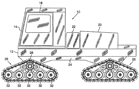
FIG. 1 is a side elevational view of a four-
track al.l-terrain vehicle showing two of its four
endless track units according to one preferred
embodiment of the invention.
FIG. 2 is a side elevational view of an
endless track unit of FIG. 1.
FIG. 3 is an enJ.arged fragmentary view of the
endless track unit of FTG. 2.
FIG. 3A is an enlarged fragmentary. view
showing the upper portion of the endless track unit of
~'TG. 3 .
~ FTG. 4 is an enlarged cross-sectional view of
the endless track unit taken along lines 4-4 of FIG. 2.
FIG. 4A is a top view of the track of FIG. 4.
- 10 -
CA 02198057 2002-12-02
FIG. 5 is a side elevational view of an
endless track unit of an alternative preferred
embodiment.
FIG. 6 is an enlarged cross-sectional view of
the endless track unit of FIG. 5 taken along lines 6-6
of FIG. 5 .
FIG. ? is a side view of the drive sprocket
wheel used in the embodiment of FIG. 5.
FIG. 8 is a top view of the drive sprocket
wheel of FIG. ?.
FIG. 9 is a top view of the track of FIG. 5.
FIG. 10 is a perspective view of the track of
FIG. 9.
DETAILED DESCRIPTION OF PREFERRED EMBODIMENTS
Useful background information on all-terrain
vehicles of this general type may be found in prior U.S.
patents 3,?87,099 and 3,85?,616 to which the reader is
encouraged to refer.
Referring to FIG. 1, a four-track all-terrain
vehicle 10 is shown having a vehicle body :12 extending
longitudinally of the all-terrain vehicle 10 from a
front end 14 to a rear end 16. A cab 18, in which an
operator sits, is located at the front end 14 and is
mounted to the top of vehicle body 12. A suitable
engine (not shown) within an engine housing 20 is
mounted to the top of vehicle body 12 near the all-
terrain vehicle's rear end 16. A fuel tank 22 far
supplying fuel to the engine is mounted intermediate the
engine housing 20 and the cab 18.
The vehicle body 12 is mounted on a chassis
24, which is substantially coextensive with the vehicle'
body 12. Four identical endless track unii~s 26 (only
two shown) support and are mounted to the chassis 24,
two on opposite sides of the chassis 24 at the front of
the vehicle and two on opposite sides of the chassis 24
at the rear of the vehicle. Each endless track unit 26
- 11 -
. 2198057
is independently mounted, driven and steerable in a
well-known manner.
Additionally, the endless track units 26 are
generally triangular shaped having an apex 28 with a
track 30 trained around and supported by a plurality of
undriven guide wheels 32.
FIGS. 2, 3 and 4 show one of the endless track ,
unite 26 of a.preferred embodiment in greater detail.
The endless track unit 26 is mounted to the chassis 24
(FIG_ 1) of the all-terrain vehicle ~.0 by a journal
tube 34 (FrG.4). A rigid frame 36 is mounted to
journal tube 34. The frame 36 includes a cross beam 38
and two sets of diverging legs -- outer legs 40a, 40b
and inner legs 42a, 42b. The inner legs 42a, 42b are
connected adjacent each other to journal tube 34 and
diverge downwardly therefrom forming an inverted V-
shaped configuration. The outer legs a0a, 40b include
ends having lower parts 46a, 46b connected to the inner
legs 42a, 42b, respectively, and upper parts 48a, 48b
connected to journal tube 34. The outer legs 40a, 40b
extend outwardly from the journal tube 34 and inner
legs 42a, 42b before turning downwardly at bends 50a,
SOb. The inner legs 42a, 42b are further supported by
_gusset~ 52 (one per leg, see FIG. 4) mounted to journal
tube 34. Outer legs 40a, 40b are similarly supported
by gussets 54 mounted to the journal tube 34. The
inner and outer legs are connected at their lower ends
to cross beam 3s, which runs longitudinally of the
endless track unit 26.
The endless track unit 26 has a drive wheel 56
located directly below and definzng apex 2e of the
generally triangular-shaped endless track unit 26.
Drive wheel 56 is rotatably driven by an axle (not
shown) within journal tube 34, the axle receiving power
through a suitable transmission from the engine in a
well-known manner.
- 12 -
219807
The frame 36 pivots about the axle (not
shown). Known carrier stops (not shown) secured to the
frame 36, preferably one on each side of the journal
tube 34 and extending upward to engage known parts (not
shown) on the chassis 24 preclude pivotal ox
oscillatory motion of the frame 36 beyond desired
limits. Each carrier atop is constructed, secured, and
positioned in a well-known manner. .
The drive wheel 56 includes a drum 58 with
sprocket disks 60a, Gob mounted at either end o~ the
drum 58 (FIG. 4). Each sprocket disk 60a, 60b has nine
teeth 61 (FIG. 3), rather than the more conventional
seven, and is preferably coated with polyurethane or
rubber to prevent ice and other debris buildup on the
sprocket disk during use. opposed sprocket disks 60a,
GOb are axially spaced-apart to form a gap 62
therebetween (FIG. 4).
Five lower undriven guide wheels 32 are
equally spaced in a line along cross beam 38 of the
triangular-shaped endless track unit 26 (FrG. 2)
including a front guide wheel 66 at one en,d and a rear
guide wheel 68 at an opposed end. Guide wheels 32
rotate on guide wheel spindles 70 (FIG. 4) extending
through an aperture in, cross beam 38 and fixedly
secured therein. Cross beam 38 maintains the guide
wheels 32 in lateral and longitudinal alignment.
Two undriven damper wheels 72a, 72b, one on
each side of the drive wheel 5f, are mounted on damper
wheel spindles 74 (FIG. 4, shown by dotted lines)
fixedly secured within housings 76 (ahowzz by solid
lines). The hous~.ng 76 and spindles 74 extend through
an aperture (not shown) in each supporting outer leg
4oa, 40b and are fixedly secured therein. Damper wheel
spindles 74 have opposed threaded ends 78, 80 or
retaining pins (not shown) and a shoulder 82 near end
~8. The damper wheels 72a, 72b are slidably mounted on
the Spindles and rotate on bearings 84 (FIG. 4)
- 13 -
2198057
encircling the spindles and houBed within the dampex
wheels 72a, 72b. The bearing and damper wheel
assemblies are rotatably secured between shoulder 82
and a hub 86 threaded on end 78 of the spindle.
Preferably, the damper wheels 72a, 72b will partially
overlap sprocket disks 60a, 60b on drive wheel 56 by
resting as closely as possible to drum 58 with~.n gap 62
between the sprocket disks 60a, Gob. This allows
optimal performance as will be further described.
l0 Additionally, the damper wheels 72a, 72b are preferably
made from a resilient material, such as rubber, to
absorb vibration.
Track 30 is trained around the outside of
drive wheel 56, damper wheels 72a, 72b and guide wheels
32 to form the generally triangular-shaped track run.
A plurality of traction bars 88, preferably constructed
of steel, extend lateralJ.y across the outside of
track 30, the bars 88 being equally spaced around the
track's periphery. wheel guides 90 axe centrally
located on the track 30 and include ears 92 extending
inwardly from traction bars 88. Guide wheels 32 pass
between ears 92 and maintain a central alignment of
track 30 as it passes over the guide wheels 32. Track
fins 9a, centrally located on the track 30, extend
outwardly from traction bars 88 and provide enhanced
traction for endless track unit 26.
A.s best shown in FIG . 2 , an ideal dowx~.ward
pitch line 96 of track 30 is defined as a down-sloping
straight line extending from the apex 28 to the a point
97 tangent to the upper portion of the froxxt guide
wheel 66. Similarly, an ideal upward pitch line 98 of
track 30 is defined as an up-sloping straight line
extending from a point 99 tangent to the upper portion
of the rear guide wheel 68 to the apex 28.
FIGS. 4 and 4A show track 3o in greater
detail. The track 30 comprises four track belts 100,
preferably constructed of rubber, two on each side of
- 14 -
2198957
the centrally located track fin 94. Traction bars 88
are attached to track belts 100 by bolts 102 which
extend through washer strips 104 bearing against the
belt's back side. A rigid drive saddle 106, preferably
having a cross-section shaped to tightly mesh between
the teeth 61 of the sprocket disk 60a, 60b as best
shown in k'IG 3A, is secured, preferably by welding, to
a traction bar 88 on either side of track fin 94 (FIG.
4 and 4A?. Holes 110 extending through wheel guides 90
permit mud and snow to escape and prevent undesirable
buildup thereof on the working surfaces of the ramps.
Openings 112 formed between track belts 100 and wheel
guides 90 allow the teeth 61 on the sprocket disks 60a,
60b to mesh with the drive saddle 106 and thus drive
track 30.
All of the described wheels maintain track 30
in a generally triangular track run. However, there
are gape or voids where the track 30 is not supported
by any of the above-described wheeJ.s. Most of these
gaps 120 (FIG. 2~ axe located along the base of the
triangular endless track unit z6 between guide
wheels 32. A f~.rst pair of larger leg gaps 122a, l2zb
is located along the legs of the endless track unit 26
between damper wheels 72a, 72b and the front and rear
guide wheels 66, 68, respectively. A second pair of
leg gaps 124, z26 is located one between the damper
wheels 72a, 72b and drive wheel 56.
As already mentioned, the damper wheels 72a,
72b are positioned as closely as possible to the drum
58 of the sprocket disks 60a, 60b. Downstream damper
wheel 72a is located slightly below the downward pitch
line 96 of the track 30, and upstream damper wheel 72b
is located slightly below the upward pitch line 98 of
the track 30. This minimizes the gaps 124, 126 located
between damper wheels 72a, 72b and drive wheel 56. In
cases where the track 30 has elongated to the point
where it has a significant amount of slack in it and
- m -
2198057
therefore the track 30 sags below its ideal pitch lines
96, 98, during operation of the all-terrain vehicle l0,
the downstream damper wheel 72b gradually raises the
track 30 from larger gap 122b to the proper pitch line,
aligz~~.ng the track in propex position to be received by
the drive wheel 56. Similarly, as the track passes
over the apex 28, the downstream damper wheel 72a
gradually lowers the track 30 from the proper pitch
line into larger gap 122x, thereby helping to keep the
i0 track 30 in proper alignment with the meshing teeth of
the drive wheel 56. However, these gaps cannot be
entirely closed because of the conflict that would
occur between the drive sprocket and the damper wheel
axles.
Previously, in light of the general resiliency
of the track 30 and its tendency to elongate with wear,
it was thought that if track 30 is left unsupported
over these gaps, track bounce will occur because
sprocket disks 60a, 60b have difficulty disengaging tl~e
track due to friction. Accordingly, various devices,
such as slides and bridges, were devised to fill the
remaining gaps but still allow the track 30 to follow
its optimal path along its pitch lines 96, 98. Means
for improving the meshing of the sprocket disks 60a,
60b with track 3o had largely been left unexplored.
However, during operation of the all-terrain
vehicle 10, the teeth of the sprocket disks 60a, sob
drivingly engage the track 30 only in the vicinity of
the extreme apex z8 of the generally triangular txack
ruxz. Known means for engaging the sprocket disks 60a,
60b with track 30 permit at least one tooth of the
sprocket disks 60a, 60b to remain driv~.ngly engaged
with track 30 below the ideal pitch lines 96, 9B of the
track 30. Normally, the track is not as taut as shown
in FIG. 2. Instead, the track slightly sags under the
weight of the traction bars 88 in larger gaps lz2a,
222b between damper wheel 72a and front guide wheel 66
- 16 -
219807
and between damper wheel 72b and rear guide wheel 68.
As a result, the engaged teeth of the known sprocket
disks 60a, 60b have a tendency to pull the track below
the downward pitch line 96_ Consequently, when the
sprocket disks 60a, Gob and txack 30 disengage, the
track bounces back toward and possibly beyond the
desired track run causing track bounce, vibration of
the vehicle i0, and undue wear of the track 30,
sprocket teeth 6~., and other drive components.
1.0 The present invention solves this problem by
providing sprocket disks 60a, 60b that do not drivingly
engage the track 30 past its ideal pitch lines 96, 98.
Thia is accomplished by providing sprocket disks 60a,
60b that have more than two teeth drivingly engaging
the track 30 along the pitch lines 96, 98 at any given
time_ As best shown in FTGS. 3 and 3A, sprocket disks
60a, 60b are approximately the same diameter as the
known disks, however the pitch of the disks is smaller
(e. g., preferably having a x.75 inch pitch rather than
the known 6.06 inch pitch) thereby providing more
teeth, here nine teeth compared to the seven teeth of
the known disks, for drivingly engaging the track 30.
As best shown in FIG. 3A, the increased number of
sprocket teeth results in more teeth, here at least
three teeth 61a, 61b, 61c, drivingly engaging the track
at its apex 28. Also, because o~ the smaller pitch
of the sprocket disks 60a, 60b over the known art, each
tooth 61 of the spxocket disks 60a, 60b releases the
track 30 at or before passing below the downward pitch
30 line 96 of track 30, thereby preventing track bounce
and track jump. The result, surprisingly, is a quiet,
smooth-running, efficient, low-maintenance,
substantially vibration-free endless track unit 26,
without the need for slides, bridges or additional
damper or guide wheels to control track bounce and
jump.
- 17 -
219807
In addition to preventing track bounce and
track jump, providing more sprocket disk teeth 61 for
drivingly engaging the track 30 requires the openings
112 formed between track belts 100 and wheel guides 90
to be closer together to permit the track 30 to
properly mesh with the~decreased pitch of the sprocket
disks 60a, 60b. As a result, more traction )oars 88 may
be added to track 30, further increasing the traction
of the vehicle 10. Also, because more sections of the
track 30 are being drivingly engaged by the drive wheel
56, the forces applied to any particular section of
txack 30 and each sprocket tooth 61 are reduced over
the known devices, thereby reducing the wear and
elongation of these parts during use.
Because the improved sprocket disk effectively
reduces track bounce and track jump, the need for
placing sliders and bridges in the various gaps is
eliminated. However, in order to protect the track 30
from derailment resulting from a severe disturbance,
like from a foreign object falling on the track 30, it
is still preferable to maintain the upstream and
downstream damper wheels 72a, 72b with this preferred
embodiment.
Moreover, because the improved sprocket disk
minimizes track bounce, the sprocket teeth 51 can be
"low profiler' with minimal risk of track jump. For
example, in an endless track unit of the invention
having a sprocket wheel with the same drum diameter as
a pxior art sprocket wheel, the low--profile sprocket
teeth 61 were over 36% shorter than the sprocket teeth
of the prior art unit. The shorter sprocket teeth
themselves help reduce the possibility of track bounce
by releasing their engagement with the track 30 sooner
than would otherwise occur. The low-profile teeth 61
also allow the damper wheels 72a, 72b to be placed
' closer to the drum 58 of the drive sprocket wheel than
_ 18 _
2198057
is possible with the longer teeth, further minimizing
track bounce.
An alternative preferred embodiment of an
endless track unit is shown in FIGS. 5-10. This
embodiment provides a unique combination of drive wheel
and track providing the advantages of the previously-
described embodiment and additional advantages as well.
As with the previous embodiment, the alternative
embodiment provides drive sprocket disks with more than
two teeth driving the track 282 along the pitch lines
296, 300 of the track 28z at any given time. However,
this embodiment offers the improved features of the
invention while eliminating altogether the need for
damper wheels 72a, 72b (FIG. 2), offering an improved
journal and spindle assembly, and providing a track 282
that reduces vibration to permit the veh~.cle to operate
at increased speeds and with a more environmentally
sensitive footprint.
FIGS. 5 and 6 show one of the endless track
units 200 of the alternative preferred embodiment in
gxeater detail. The endless track unit 200 ig mounted
to the chassis 24 (FIG. 1) of the all-terrain vehicle
10 by an outer journal tube 202 (FIG. 6). A rigid
frame 204 is mounted to outer journal tube 202. The
frame 204 (more clearly shown in FIG. 5) includes a
cross beam 206 and two sets of diverging legs -- outer
legs 208a, 208b and inner legs 210a, 210b.
The inner legs 210a, 210b axe connected
adjacent each other to outer journal tube 202 and
diverge downwardly therefrom forming an inverted V-
shaped configuration. The outer legs 208a, 208b
include ends having lowex paxts 212a, 212b connected to
the inner legs 210a, 210b, respectively, and upper
parts 214a, 214b connected to outer journal tube 202.
The outer legs 208a, 208b extend downwardly from the
outer journal tube 202 and inner legs 210a, 210b
forming another inverted ~1-shaped configuration. The
- 19 -
219~0~7
inner legs 210a, 210b are further supported by gussets
(xzot shown) mounted to outer journal tube 202 and outer
legs 208x, 208b are similarly supported by gussets (not
shown) mounted to the outer journal tube 202. The
inner and outer legs are connected at their lower exzds
to cross beam 206, which runs longitudinally of the
endless track unit 200. Two carrier stops (not shown),
identical to the ones described in the previous
embodiment, maintain the frame 204 in alignment with
respect to the vehicle.
The endless track unit 200 has a drive wheel
216 located directly below apex 21S of the triangular-
shaped endless track unit 200. Drive wheel 216 is
rotatably drivez~ by an axle 220 operably secured within
inner journal tube 222, the axle 220 receiving power
through a suitable transmission from the engine.
As best shown in FZG. 6, a journal assembly
224 contains a self lubricating replaceable journal
liner 226, preferably nylon, that is removably secured
between the outer journal tube 202 and inner journal
tube 222. The journal liner 226 is retained by a ring
230, preferably steel, secured on the opposite side of
the inner journal tube 222. Two snap rings 232a, 232b
are inserted into grooves (not shown) in the outer
journal tube 202 operably secure the outer journal tube
202 and inner journal tube 222 together with the
journal liner 226 thereby secuxed therebetween. The
journal liner 226 allows the frame 204 to oscillate
about the inner journal tube 222 as with known devices,
but it provides a way to replace a relatively
inexpensive liner rather than a complete frame 204 when
worn.
Drive wheel 216 includes a drum 240 with
sprocket disks 242a, 242b mounted at either end of the
drum 240 (FIG. 6). Opposed spxocket disks 242a, 242b
are axially spaced-apart to form a gap 244
therebetween.
- 20 -
2198057
As best shown in FIGS. ~ and 8, each sprocket
disk 242a, 242b comprises a flat disk 246, preferably
aluminium, with cogs 248, preferably thirteen of them
and also aluminium, positioned equidistance around the
circumference of the flat disk 246, with each cog 248
rigidly secured within a bore 249 of the flat disk 246,
preferably by welding, and extending perpendicularly
therefrom. The exposed area of each cog 248 has a
generally tear-drop cross-section while the area of
each cog secured within the bore 249 has a circular
cross-section, as shown in FIG. 7. Each cog 248 forma a
tooth of the sprocket disk. Each sprocket disk is
coated with a 1/8 inch to 3/16 inch thick coating of
ice repellant material, preferably polyurethane, to
prevent ice and other debris build-up on the sprocket
disk during use.
Five lower undriven guide wheels 250 are
equally spaced in a line along cross beam 206 of the
generally triangular-shaped endless track uz~i.t 200
(FIG. 5) and including a fxont guide wheel 252 at one
end and a rear guide wheel 254 at an opposite end. As
showxz in FIG. 5, the cross beam 206 includes a
telescoping wheel end support 256, preferably one at
each end of the cross beam 206. The telescoping wheel
end support 256 includes a wheel extension beam 258
slidably received within and extending longitudinally
from the cross beam 206. An adjustor nut 260 is
rigidly secured to the cross beam 206 adjacent the
wheel extension beam 258. A threaded adjustor bolt 262
is secured to wheel extension beam 258 and threadably
received in the adjuster nut 260. Preferably, the
adjuster bolt 262 is aligned with the center line of
the guide wheels 250 to prevent uneven distribution of
the forces acting on the guide wheels 250 and thereby
reduce the likelihood of the guide wheels 250 falling
out of alignment or experiencing uneven wear. By
adjusting the adjuster bolt 262, the appropriate guide
_ 21. _
219807
wheel 252, 254, here the front guide, wheel 252, will
move, permitting it to be adjusted forward or backward
into a desired position to adjust tautness of the track
282.
Each guide wheel 250, is preferably made from
a resilient material, such as rubber, to absorb
vibration. The center guide wheels 250 rotate on guide
wheel spindles 264 (FIG. 6) extending through an
aperture in cross beam 206 and fixedly secured therein.
l0 The guide wheel spindles 264 for the front and rear
guide wheels 252, 254 extend through apertures in the
wheel extension beam 258. The cross beam 206 and wheel
extension beam 25B maintain the guide~wheels 250 in
vertical and lateral alignment.
Eack~ gu~.de wheel spxz~dle 264 has a first end
266, an opposite threaded end 268, and a shoulder 270
near threaded end 268 which serves as a beaxxng
shoulder and a seal ring. Preferably, the outer
diameter of the shoulder 270 is coated with a suitable
ceramic paint, making for a hard and smooth seal
surface. The guide wheel 250 is slidably mounted on
the spindle 264 and rotate on bearings 272 (FIG. 6l
encircling the spindle 264 and housed within the guide
wheel 250. A pair of bearings and a guide wheel 250
are rotatably secured between shoulder 270 and hub 274
with a washer 276 and nut 278 threaded on threaded end
268 of the spindle as shown in FTG. 6. The shouldered
spindle for receiving the bearing, reduces the number
of parts required over the previous spindle assembly,
permits each guide wheel. 250 to be pre-loaded during
manufacture, and increases the time between required
greasing of the idler bearings from about 8 hours of
operation to approximately S00 hours of operation.
Track 282 is trained about the outside of
drive wheel 216, and guide wheels 250, 252, 254 to form
a generally triangular-shaped track run. for each
- 22 -
219807
endless track unit 200, two sprocket disks 242a, 242b
are aligned along and secured to the drive wheel 216.
As best shown in. FzGS. 6, 9 and 10, track 282
is a one piece endless molded rubber belt with
internally cast composite stiffener rods (not shown),
preferably fiberglass composite and positioned evexy
4.166 inches, running perpendicular to the track run.
Internally cast flexible, stretch-resistent chords (not
shown), preferably constructed of a combination of
~0 Kevlar, nylon, and steel cable, run parallel to the
track run. One known manufacturer of endless tracks
containing such materials is Camoplast, Inc., located
in Platteburgh, New York, United States of America.
Molded generally triangular shaped drive lugs
284, molded in place and preferably constructed o~ hard
rubber, are positioned on the inside of track 282 to
engage and mesh with the cogs 248 (See Fig. 5) for
driving the track 282. As best Shawn in FIG. 5, the
generally tear-drop shape of the cogs 248 allows each
cogs 248 to drive the track close to the base of each
drive lug 284. The drive lugs 284 are also spaced
apart to serve as wheel guides. In use, the guide
wheels 250, 252, 254 pass between the drive lugs 284
arid maintain a central alignment of track 282 as it
passes under the guide wheels 250, 252, 254 as shown.
As shown in FIGS. 9 and 10, a molded tread has
txaction bars 286, preferably of rubber, extending
laterally across the outside of track 282, the traction
bars 286 being equally spaced axound the txack's
periphery. Lateral grooves 288 in the tread further
~.mpxove the traction of the vehicle.
As shown in FIG. 6, a pair of scrapers 290a,
290b, preferably constructed of hard rubber, molded in
place as part of the track, and having a generally
txiaz~gular crass section, are positioned inside of the
track 282. One scraper of the pair of scrapers, here
scraper 290a, is positioned adjacent outer drive lug
- 23 -
2198057
292a and extends to outer track edge 294a as shown in
FIGS 6 and 10. Similarly, the other scraper of the
pair of scrapers, here scraper 290b is positioned
adjacent outer dxive lug 292b and extends to outer
track edge 294b. Preferably, the pair of scrapers
290a, 290b are positioned at every eighth set of drive
lugs as shown in FIG. 5.
As best shown iri FZG. 6, in use, the pair of
scrapexs 29oa, 290b travel along the track path axed
extend toward the center of the generally triangular-
ehaped track run with one scraper of the pair of
scrapers, hexe scraper 290b, extending toward the
journal assembly 224. As snow, ice, sand; or other
debris builds up in the area about the journal assembly
224, the scraper extending toward the journal assembly
224 clears away this debris before it can disrupt
operation of track 282.
In the configuration shown in FIG. 6, the
other scraper of the pair of scrapers, here scraper
290a, does not operate to clear debris. However, for
ease of installation and far reducing the likelihood of
uneven wear of the track, the txack is reversible so
that either outer track edge 294a, 294b of the track
may be positioned toward the center of the vehicle 7Ø
In the event the track were installed in reverse as
described, the other scraper, here scraper 290a, would
then be positioned over the journal assembly 224. The
pair of scrapers 290a, 290b permit the efficient
clearing of debris about the journal assembly, while
still allowing the track to remain completely
reversible.
Ae best shown iri FIG. 5, an ideal downward
pitch line 296 of track 282 is defined as a down-
sloping straight line extezzding from the apex 218 to a
point 298 tangent to the upper portion of the front
guide wheel 252. Similarly, an ideal upward pitch line
300 of track 292 is defined as an up-eloping straight
- 24 -
219807
line extending from a point 302 tangent to the upper
portion of the rear guide wheel 254 to the apex 218.
This alternative preferred embodiment operates
much the same as the first preferred embodiment. More
than two teeth, here three cogs 248a, 248b, 248c (FIG.
5), drivingly engage the track 282 along its pitch
lines 300, 296. Accordingly, as more fully described
with the previously described preferred embodiment, the
tendency of the sprocket disk 242a, 242b to remain
drivingly engaged with the track 282 below the downward
pitch line 29~ is eliminated and track bounce and track
skip are eliminated.
In addition, because of the improved materials
used in the track 282, the track 282 is stretch
resistant during use and wear. Unlike traditional
rubber tracks, the stretch-resistant chords and
stiffener rods embedded within the improved track 282
significantly reduce the likelihood of the track 2s2
stretching during uee. Accordingly, the track 282 may
be instal7.ed taut, with little chance of it loosening
during use arid little chance of the drive lugs 284
falling out of alignment with their corresponding cogs.
The track 282 may be pulled taut simply by adjusting
the telescoping wheel end support:256, which also
permits easy removal and replacement of track 282.
With this improved configuration, the need for sliders,
bridges, and damper wheels is eliminated.
The stretch-resistant track 282 combined with
the increased number of teeth, as well as increased
surface area of each tooth contacting the lugs 284,
permit each disk to more evenly distribute the forces
acting ox~ the track 282. As a result, track 282 is
more reliable and less prone to falling out of
alignment or wearing out compared to the known track
and sprocket disk configuratior~a.
Also, because cogs 24B drivingly engage the
lugs 284 on the inside of the track 282, rather than
- 25 -
2198057
through openings in the track as with known previous
devices, the need for holes extending through the track
to accommodate sprocket teeth is eliminated.
Accordingly, the track 282 may be and is preferably a
continuous rubber surface, thereby offering a much
larger surface area contacting the ground at any given
time. In addition to the improved traction associated
with such a configuration, another benefit includes the
fact the weight of the vehicle is more widely and
evenly distributed on the ground, resulting in the
track 282 becoming leas deeply imbedded in the ground
as the vehicle travels over it. As a result, the track
282 leaves a smaller and less disruptive footprint
behind. Such a small footprint permits the veh~.cle to
operate in environmentally sensitive areas without
unduly disnzpting the terrain.
Also, elimination of steel traction bars in
the alternative preferred embodiment allows the vehicle
to operate relatively vibration free even at high
speeds on hard surfaces.
Having described and illustrated the
principles of the invention with reference to preferred
embodiments thereof, it will be apparent that these
embodiments can be modified in arrangement and detail
without departing from the principles of the invention.
For example, although the sprocket disks have
been shown to have nine and thirteen teeth, any sized
ar shaped sprocket disk that permits more than two
teeth to drivingly engage the track and release ~.t at
or above the downward pitch line could be used.
Additionally, although the endless track unit
26 of the first embodiment is shown with two damper
wheels 72a, 72b {FIG. 2), it can easily be modified to
have only one damper wheel. In the one damper wheel
embodiment, the damper could be on the upstream or, the
preferable downstream side. Moreover, although the
damper wheels are shown nested close to the drive
- 26 -
2198057
wheel, they could be located further downstream and
upstream. Also, the improved journal assembly having a
removable journal liner, the improved guide wheel
spindle, and the addition of ice scrapers discussed in
S conjunction with the alternative preferred embodiment
are equally applicable to the first preferred
embodiment.
Finally, although the drive wheel was shown as
a dual-sprocket wheel, it is possible to have other
forms of drive wheels, such as a single sprocket wheel.
In view of the wide variety of embodiments to
which the principles of the invention can be applied,
it should be apparent that the detailed embodiments are
illustrative only and should not be taken as limiting
1S the scope o~ the invention. Rather, the claimed
invention includes all such modifications as may come
within the scope of the following claims and
equivalents thereto.
- 27 -