Note: Descriptions are shown in the official language in which they were submitted.
2198528
ROTATABLE SHUTTLE TRANSFER UNIT
Field of the Invention
The present invention relates to the transferring of
a workpiece between work stations, and more particularly,
to a shuttle transfer unit that carries and rotates the
workpiece along a predetermined path of travel between a
first work station and a second work station.
Background of the Invention
Generally, shuttle transfer units, of the general type
of which the present invention is concerned, typically
include a fixed frame spanning across a plurality of work
stations. The shuttle transfer unit transports a workpiece
between work stations, and each work station typically
performs some type of manufacturing or assembly process on
the workpiece.
When these shuttle transfer units load and unload the
workpiece to and from the work stations, the workpiece must
be orientated in a proper manner to allow for the proper
fixturing and processing of the workpiece in the associated
work station. This can become a rather difficult task when
the workpieces have rather large and irregular geometries,
such as motor vehicle chassis and frames.
Often, such motor vehicle frames and chassis must be
rotated or rolled over 180° such that both sides of the
chassis or frames may be made accessible for various types
1
2198528
of machining and welding processes. Currently, due to the
size and shapes of such workpieces, the workpieces are
typically re-orientated or rotated at a separate work
station. The workpieces are then transported to a
subsequent work station wherein the workpieces are f ixtured
for subsequent sequential processing of the workpiece.
Such handling of the workpiece requires the additional
space, equipment and time required for simply re-
orientating the workpiece with respect to the production
line. In addition, each work station requires the
workpiece to be clamped or fixture, thus requiring new
datums and references to be established and thereby
increasing the range of tolerances. Obviously, such
processing breeds inefficiencies and is undesirable in a
production environment.
It would be desirable to provide a shuttle transfer
unit that re-orientates a large, irregular workpiece, such
as a motor vehicle chassis or frame, while transferring the
workpiece from one work station to a subsequent work
station without requiring the need for a separate and
additional work station for re-orientating the workpiece.
Summary of the Invention
The present invention provides a rotatable shuttle
transfer unit for transferring a workpiece from a first
work station to a second work station along a predetermined
path of travel wherein a carriage means carries the
2
~ I %'~5Z8
workpiece along the predetermined path of travel and
rotates the workpiece from a first angular orientation to
a second angular orientation with respect to an axis of
rotation. Preferably, the carriage means rotates the
workpiece while carrying the workpiece along the
predetermined path of travel.
The shuttle transfer unit also provides a means for
transporting the carriage means along a guiderail which
extends between the first work station and the second work
station. An endless belt means reciprocally drives the
carriage means in guided movement along the guiderail. The
endless belt means extends from one end of the guiderail
means to an opposite end of the guiderail means and is
connected to the carriage means. A power driving means,
which is mounted to the guiderail and coupled to the
endless belt means, drives the endless belt means.
The shuttle transfer unit also provides a means for
reciprocally moving the workpiece in a direction
substantially normal to the predetermined path of travel.
Preferably, the reciprocal moving means moves in a vertical
direction so as to provide a vertical lift portion for
loading and unloading the workpiece to and from the work
stations. Thus, the predetermined path of travel is
preferably linear and horizontal.
The carriage means of the shuttle transfer unit also
provides a means for releasably engaging the workpiece.
This allows the shuttle transfer unit to load and unload
3
CA 02198528 2003-03-10
the workpiece t.o and from t:he work stations. Preferably,
the relf=asable ~~~n~gaging mear..s provides a means for
releasab:iy clamping t_he workpiece.
According tc:~ an aspect of the present iriv~~ntion,
there if provided a rotatable shuttle transfer unit for
transferring a wc~rkpiece from a first work station to a
second work stati~::>n along a predel:.ermined path of -travel,
and said workpiec,~: having an axis for rotation thereabout
comprising:
a guiderail extending between raid first work
station and said second work station; and
a carriage mo~r<~bly swpporte:d and guided b_y said
guiderail. carriage for carrying said workpiece along said
predetermined path :o.f t:ra~~el between sa_i.d first/ work
station and said second wcrk statior_ arid simultaneously
rotating said workpiece frc~m a first angular orientation
to a second angula:;.r c~rient;at.i«n with respect to said axis
of rotation.
Acccrding to aruc_other aspect= of the invention, there
is pro~aided a rc>t:atable shutt:Le transfer u.zit for
transferring a workpiece from a first work station to a
second work static;n along a predetermined path of gravel,
and said workpiecfa having an axis for rotation thereabout
comprising:
a c~uiderail e~;tending between said first work
station and said second word: station;
carriage means nor rel.easably engaging said
workpiece at one or said first and second work stations
wherein said carri.ac~e means is movably supported and
guided by said gt.zzderail for reci.proca ~ movement along
said guiderail;
means, coup.L.ec~ to said carriage means, for
transporting said carriage means along s~~id guiderail and
4
CA 02198528 2003-03-10
carrying said workpiec:e alone said predetermined path of
travel; and
means, cou~:~l.ed to said carriage means, for
simultaneously r~.~tating said workpiece from a first
angular orientatic>n r_o a second angular orientation with
respect t:o said a,~:is of rotation.
According tc:~ a furtr.er aspect of the invention,
there is provideca rotatable shuttle transfer unit for
transferring a wcrkpiece f_~~om a first work stat:ron to a
second work static:>r: <along a pr.edet~erminec~ path of t=ravel,
and said workpiece havirLg an axis for rotation thereabout
comprising
an overhead guiderail extending between and over
said fir~.-t and second work :.stations;
a p,~ir of s:im_i_~_ar carriages movab.Ly supported and
guided by said guidf~rail Eor reciprocal movement along
said gu:iderail anc:~ raid pair of similar carriages spaced
a predetermined di~;tance from one another along said
guiderail;
means, connected to each of said carriages, for
releasably clamping said woz:kpie~~e;
endless belt means, e~,tendiny from one end of said
guiderail to an opposite end of said guiderail and
connected to at least one ~~f said carriages, for
reciprocally driv~r~g said carriages in guided movement
along said guiderai_1 and moving said workpiece alo ng
a
predetermined path of t:ravel_; and
mean:, connec~t;ed to ~:.~ac~h of said carriage:, for
rotating raid worl~::piece from a first angular orientation
to a second angular orientation with respect to said axis
of rotation whil2~ acid woYkpiece i.s moving along said
predetermined path of travel.
~a
CA 02198528 2003-03-10
Other obj ect;~, advantages and app _ications of the
present invention w_i::Ll. become apparent to those :>killed
in the a:rt when the follcwing description of t=he best
mode cont.empl.ated for pra<aicing the :invent=~on is read in
conj unction with t: he ac:cornp<~n~;~i.ng drawings .
Brief,. I;~escri~tion, of_the, Drawings
The descript_ i.on here i.n ma.~es :reference to the
accompanying drawings wherein like re:Eerence and numerals
refer to hike E~art.s throu.gh~~ut several vievas, and
wherein::
Fidur_e 1. is ~ front= el_evat:ional v=iew of the ~>huttle
transfer unit in accordance with t:~e present invert=ion;
Figu~__°e 2 is « too view of the shutt:.le transfer unit;
Figu~°e 3 is r c:rcss sectic>na.1 view taken along line
3-3 of Figure 1;
Figure 4A i. s a schematic diagram showing the
workpiec:e raised ~:~bove the rust= work station at one end
of the predetermined path of: travel;
Figure 4B is a schematic diagram showing the shuttle
transfer unit mic:~wa~Y~ along the predetermined path of
travel wherein the workp:iece is shown rotated 90°ctegrees;
Figure 4C is a schematic diagram showir~.g the t~huttle
transfer unit. at the oppc~.ite end of the predetermined
path wherein the u,rorkp:iece is positioned above the second
w o r k -- .~s
4b
218528
station;
Figure 5 is a top view of one end of the guiderail
showing the continuous drive belt and shock absorbers; and
Figure 6 is a schematic perspective view showing the
mounting arrangement of the clamps and their respective
movement.
Detail Description of the Preferred Embodiment
Referring to the drawings, the present invention will
now be described in detail with reference to the preferred
embodiment.
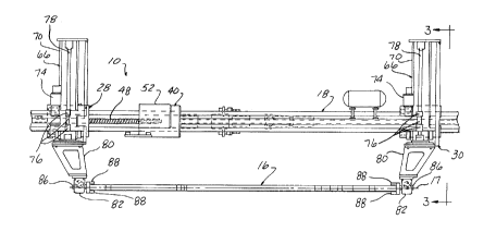
Figures 1 and 2 shows a rotatable shuttle transfer
unit 10 as described in the aforesaid invention. The
rotatable shuttle transfer unit 10 provides a guiderail
means that extends between a f first work station 12 and a
second work station 14 and a carriage means that is movably
supported on the guiderail means. The carriage means has
a means for releasably engaging a workpiece 16, such as a
motor vehicle frame or chassis. Although the present
invention is not limited to the workpiece 16 being a motor
vehicle frame or chassis, it should be noted that the
present invention is ideally suited for the workpiece 16 to
be of a structure similar to a motor vehicle frame or
chassis. The carriage means is transported along the
guiderail means such that the workpiece 16 is carried along
a predetermined path of travel. In addition, the carriage
means may provide a means for rotating the workpiece 16
5
2198528
from a first angular orientation to a second angular
orientation with respect to an axis 17 of the workpieCe 16
for rotation thereabout. The rotatable shuttle transfer
unit 10 may also provide a means for reciprocally moving
the workpiece 16 in a direction normal to the predetermined
path of travel so as to allow for the loading and unloading
of the workpiece 16 to and from the first and second work
stations 12, 14.
To movably support the carriage means between work
stations 12, 14, the guiderail means may provide an
overhead guiderail 18 which extends over and between the
first and second work stations 12, 14, as seen in Figures
1-4C. The guiderail 18 has a substantially C-shaped cross
section 20 wherein the guiderail 18 provides a
substantially vertical member 22 and a pair or similar
opposing substantially horizontal members 24 extending
transversely from each end of the vertical member 22. A
pair of similar running rails 26 extend outwardly from the
opposing horizontal members 24. The running rails 26 are
substantially parallel to the vertical member 22 and extend
the entire length of the guiderail 18.
In order for the rotatable shuttle transfer unit 10 to
transfer the workpiece 16 from the first work station 12 to
the second work station 14, the carriage means provides a
pair of substantially similar carriages 28, 30 movably
supported and guided by the guiderail 18 for reciprocal
movement along the guiderail 18. Each of the carriages 28,
6
2198528
30 provides a substantially similar frame 32 for supporting
the carriages 28, 30 on the guiderail 18. The frame 32 of
the carriages 28, 30 includes a carriage plate 34 that
spans across the width of the guiderail 18. A plurality of
roller assemblies 36 are provided at opposite ends of the
carriage plate 34 to engage the running rails 26 and guide
the carriages 28, 30 for horizontal movement along the
guiderail 18. Preferably, each of the carriages 28, 30
provides three equally spaced roller assemblies 36 at each
of the opposite ends of each carriage plate 34. As seen in
Figure 5, a shock absorbing means having a pair of similar
shock absorbers 38 mounted at each end of the guiderail 18
may be utilized to absorb kinetic energy from the moving
carriages 28, 30 should the carriages 28, 30 extend in an
over travel position and approach the ends of the guiderail
18.
As seen in Figures 1-2, the carriages 28, 30 are
spaced at a predetermined distance along the guiderail 18.
A means for adjusting the distance between the carriages
28, 30 on the guiderail 18 is provided by a linear
adjustment carriage 40 spaced between the two carriages 28,
30. The linear adjustment carriage 40 is movably supported
and guided on the guiderail 18 in a manner similar to the
two carriages 28, 30, wherein three equally spaced roller
assemblies 42 are mounted at each of the opposite ends of
the carriage plate 44 of the linear adjustment carriage 40.
The linear adjustment carriage 40 has a fixed bar 46
7
2198528
having a hollow rectangular cross section with one of its
ends connected to the linear adjustment carriage 40 and its
other end connected to one of the two carriages 28, 30.
The opposite end of the linear adjustment carriage 40 has
a worm gear or screw 48 extending outward from the linear
adjustment carriage 40 and substantially parallel to the
guiderail 18 wherein the screw 48 is received by a threaded
engagement 50 in the frame 32 of the other of the two
carriages 28, 30. A reversible motor 52 is provided on the
linear adjustment carriage 40, and the reversible motor 52
may rotate the screw 48 in either direction so as to
increase or decrease the linear distance between the two
carriages 28, 30 along the guiderail 18. The linear
distance between the two carriages 28, 30 may require
adjustment when different shape and size workpieces 16 are
processed by the shuttle transfer unit 10.
In order to drive the carriages 28, 30 along the
guiderail 18, the endless belt means provides a continuous
drive belt 54 which extends from one end of the guiderail
18 to an opposite end of the guiderail 18. As seen in
Figure 5, a sprocket 56 is mounted at each end (only one
end shown) of the guiderail 18 such that the drive belt 54
has an upper and lower portion 58, 60, respectively,
extending between and substantially parallel to the
horizontal members 24 of the guiderail 18. A reversible
drive 62 powers rotation of the sprockets 56 and thus
drives rotation of the drive belt 54 in either direction.
8
219s52s
At least one of the two carriages 28, 30 has its associated
frame 32 connected to an upper or lower portion 58, 60 of
the drive belt 54. In the preferred embodiment, only one
of the- carriages 28, 30 has a drive belt mount 64 which
extends outward from the carriage plate 34 and is connected
to the lower portion 60 of the continuous drive belt 54, as
seen in Figure 3.
To lift and lower the workpiece 16 to and from the
work stations 12, 14, the reciprocal moving means moves the
workpiece 16 in a direction substantially normal to the
predetermined path of travel. Preferably, the
predetermined path of travel is substantially horizontal
and substantially parallel to the guiderail 18, and thus,
the reciprocal moving means provides vertical movement that
is substantially normal to the predetermined path of
travel. As seen in Figures 1-3, the reciprocal moving
means provides a vertical lift portion 66 wherein the frame
32 of the carriage 28, 30 supports a pair of substantially
parallel and opposing running rails 68 connected to the
carriage plate 34 and extending away from the guiderail 18.
An elongate substantially U-shaped portion 70 provides
rollers 72 extending laterally from its ends wherein the
rollers 72 are supported in tracks of the running rails 68
to allow for the U-shaped portion 70 to roll or slide
vertically along the running rails 68.
In order to power vertical reciprocal movement of the
U-shaped portion 70 along the running rails 68, the
9
21y8528
vertical lift portion 66 provides a reversible motor 74 and
a series of pulleys 76 to lift and lower the U-shaped
portion 70. The motor 74 is attached to the frame 32 of
the carriage 28, 30, and the series of three staggered
pulleys 76 extend outward from the motor 74. A timing belt
78 is connected to a top portion of the U-shaped portion
70, and the timing belt 78 is weaved through the series of
pulleys 76 and connected to a bottom portion of the U-
shaped portion 70. The motor 74 drives the pulleys 76
which in turn feed the timing belt 78 through the pulleys
76 to provide for the vertical reciprocal movement of the
U-shaped portion 70.
The vertical lift portion 66 of each of the carriages
28, 30 has a substantially trapezoidal shaped bracket 80
connected to the lower end of the U-shaped portion 70.
Each of the trapezoidal brackets 80 extend vertically
downward and have a small housing 82 mounted to the bottom
of the trapezoidal bracket 80. The small housings 82
provide for rotational support of a releasable engagement
means for engaging the workpiece 16. As seen in Figures 1,
3, and 6, the releasable engagement means provides a linear
elongate bar 84 with an axle shaft 86 integral with and
extending substantially normal from the elongate bar 84.
The axle shaft 86 is received and rotatably supported by
the housing 82 for rotation about the longitudinal axis of
the axle shaft 86. The elongate bar 84 has a releasable
clamping means mounted at each end of the elongate bar 84.
21988 28
Each of the releasable clamping means provides a pair of
power actuated clamps 87 with opposing clamping arms 88
that are pneumatically power driven between a closed or
clamped position and an open or unclamped position. To
open or move to the unclamped position, the clamping arms
88 pivot and rotate outwardly away from the workpiece 16 so
that the clamping arms 88 clear the workpiece 16 when the
workpiece 16 is unloaded into the work station 12; 14 and
the clamping arms 88 are lifted by the vertical lifting
portion 66. It should be noted that the present invention
is not limited to the specific structure of the clamps 87
as defined, but rather, the present invention may include
any structure or clamp adapted for the particular structure
of the workpiece 16.
In order to rotate the workpiece 16, a reversible
motor 90 is connected to the small housing 82, and the
reversible motor 90 cooperatively engages the axle shaft .86
in which the elongate bar 84 is connected thereto. The
power actuated clamps 87 are mounted to the elongate bar
84, and thus, when the workpiece 16 is clamped by the
clamping arms 88, the motor 90 rotates the workpiece 16
about the longitudinal axis 17 of the shaft 86. Preferably,
the axis 17 of the workpiece 16 is coaxially aligned with
the longitudinal axis 17 of the axle shaft 86, and thus,
the workpiece 16 is rotated from a first angular
orientation to a second angular orientation with respect to
the axis 17. In the preferred embodiment, the workpiece 16
11
2198528
is rotated 180° between the first and second angular
orientations with respect to the axis 17 of rotation.
In operation, the clamping arms 88 of the rotatable
shuttle transfer unit 10 releasably engage the workpiece 16
at the first work station 12. The vertical lift portion 66
lifts the workpiece 16 from the first work station 12
towards the guiderail 16 without rotating the workpiece 16,
as seen in Figure 4C. The continuous drive belt 84 drives
both carriages 28, 30 along the guiderail 16 or
predetermined path of travel while the reversible motor 90
rotates the workpiece 16 180° about the axis 17 of
rotation, as seen in Figure 4B. Once the carriages 28, 30
have reached the end of the predetermined path of travel
and the workpiece 16 has completed its rotational movement,
as seen in Figure 4C, the vertical lift portion 66 lowers
the workpiece 16 into the second work station 18. The
releasable clamps 87 release the workpiece 16, and the
vertical lift portion 66 lifts the releasable engaging
means away from the second work station 14 toward the
guiderail 16, wherein the carriages 28, 30 return to the
first work station 12 to sequentially engage a subsequent
workpiece.
It should be noted that the invention is not limited
to the workpiece 16 being rotated while moving along the
predetermined path of travel, but rather, the present
invention may include the workpiece 16 rotating and moving
along the predetermined.path of travel sequentially, or in
12
2198528
other words, at different times. In addition, the vertical
lift portion 66 may also lift and lower the workpiece 16
while the workpiece 16 is rotating and moving between work
stations 12, 14.
While the invention has been described in connection
with what is presently considered to be the most practical
and preferred embodiment, it is to be understood that the
invention is not to be limited to the disclosed embodiments
but, on the contrary, is intended to cover various
modifications and equivalent arrangements included within
the sphere and scope of the appended claims, which scope is
to be accorded the broadest interpretation so as to
encompass all such modifications and equivalent structures
as is permitted under the law.
13