Note: Descriptions are shown in the official language in which they were submitted.
2 1 q8573
Sheet collecting device for collecting
sheets of different dimensions on supports
BACKGROUND OF THE INVENTION
Field of the Invention
The invention relates to a sheet collecting device
for selectively collecting sheets of different dimensions
on supports, comprising a number of supports located above
one another, a sheet feed path which extends as far as the
supports and guides which lead a sheet from the sheet feed
path to a selected support.
Description of Background Art
A sheet collecting device is disclosed in PCT patent
application WO 94/15865 wherein the device comprises a
sheet feed path which extends in a vertical direction
along a side edge of supports which are located above one
another. Sheet transport paths are provided with sheet
transport rollers which extend above each support in order
to feed sheets which, seen in the direction of sheet
transport, are shorter than the supports as far as an edge
of a support which is opposite the side edge of the
supports where the vertical sheet feed path extends.
A disadvantage of this known device is that the
transport means above each support limit the effective
collecting height between two supports.
2 1 ~8573
--2--
OBJECTS AND SUMMARY OF THE INVENTION
The object of the present invention is to provide a
device whereby sheets, irrespective of their format, which
are collected on a support lie on top of one another with
one edge to facilitate extraction of the sheets with one
hand. The device of the present invention does not have
the disadvantages of the aforementioned known device.
This task is solved according to the present
invention in that at least one of the supports located
below the uppermost support is movable between a
collection position in which sheets can be collected on
said support and an extraction position in which collected
sheets can be extracted from said support.
As a result, sheets which are smaller than the
supports can be easily extracted from the device without
the trailing part of sheets to be collected having to be
transported over a support.
In one advantageous embodiment of the device
according to the present invention a support in the
extraction position lies in the same plane as in the
collection position but is displaced in a direction at
right angles to the direction in which a sheet is fed onto
the support.
As a result, even small collected sheets can be grasped at
the successive trailing edges lying on top of one another
and can be extracted in a direction at right angles to the
sheet feed direction.
In one advantageous embodiment of a device according
to the present invention, every support can also be moved
between a first collection position and a second
collection position, which collection positions are
displaced by some distance in relation to one another in
a direction at right angles to the direction in which a
sheet is fed onto the support.
As a result, common guide means can be used along
21 98573
which the support can be displaced between the collection
positions and the extraction position.
In a further advantageous embodiment, on every
support located below the uppermost support there is a
coupling to link said support with a block which is
movable back and forth over a distance corresponding to
the distance between the first and second collection
position and to disconnect the support from the block on
displacement of the support into its extraction position,
which coupling is preferably a magnetic coupling which can
be disengaged manually.
As a result, a support can easily be put into its
extraction position by hand from every collection position
and every position in between and after the sheets have
been extracted can be replaced into a position determined
by the current position of the block.
According to another aspect of the present invention,
first detection means are provided to detect every
support in the first collection position furthest away
from the extraction position, and control means are
provided which can automatically position a support into
the first collection position before the start of a period
in which sheets can be collected on a support which is
still empty.
As a result, in the extraction position of the
support the bottom sheets on said support are pushed out
the furthest so that said sheets and sheets lying
displaced thereon can be extracted easily without great
risk of the bottom sheets not being grasped when extracted
and being left behind.
Further scope of applicability of the present
invention will become apparent from the detailed
description given hereinafter. However, it should be
understood that the detailed description and specific
examples, while indicating preferred embodiments of the
2 ~ 98~73
--4--
invention, are given by way of illustration only, since
various changes and modifications within the spirit and
scope of the invention will become apparent to those
skilled in the art from this detailed description.
BRIEF DESCRIPTION OF THE DRAWINGS
The present invention will become more fully
understood from the detailed description given hereinbelow
and the accompanying drawings which are given by way of
illustration only, and thus are not limitative of the
present invention, and wherein:
Fig. 1 is a perspective view of a device according to
the present invention;
Fig. 2 is a front elevation of the device of Fig. 1;
Fig. 3 is a top plan view of the device of Figs. 1
and 2;
Fig. 4 is an enlarged detail of the top plan view of
Fig. 3;
Fig. 5 is another enlarged detail of the top plan
view of Fig. 3;
Fig. 6 is a view along line VI-VI in Fig. 4; and
Fig. 7 a view along line VII-VII in Fig. 5.
DETAILED DESCRIPTION OF THE PREFERRED EMBODIMENTS
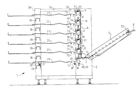
The sheet collecting device shown in the Figures 1
and 2 includes a frame 1 with a pillar-shaped part 2 which
can be placed against the side of a printer unit of which
only the exit opening 3 for printed sheets is shown in
Fig. 2. On the pillar-shaped part 2 a sheet transport
unit 5 is secured for pivoting around shaft 4 so that the
sheet collecting device may be connected to printer units
with exit openings 3 at different heights. The pillar-
shaped part 2 accommodates a sheet transport path 6 which
extends substantially vertically. The bottom 7 of said
path 6 adjoins the sheet transport path of the hinged
2 1 98573
sheet transport unit 5. The vertical sheet transport path
6 has pairs of transport rollers 8 at regular intervals
and deflector elements 9 to 14 to divert sheets fed on
transport path 6 off the path into short, horizontal exit
paths 15 to 20 which are provided with transport rollers.
The uppermost deflector element 9 is fixed in a
position to divert a sheet into exit path 15. Exit path
15 discharges into a sheet collecting tray formed by
support 21. The other deflector elements 10 to 14 can
selectively be put into an inactive position which is
shown in Fig. 2, and into an active position in which they
can selectively divert a sheet fed in path 6 into one of
the exit paths 16, 17, 18, 19 or 20. Each of the exit
paths 15 to 20 discharges into a sheet collecting tray
formed by supports 22 to 26 which are located at regular
intervals under support 21. Every support 21 to 26 has an
effective width of 1100 mm and an effective length of 1240
mm which is suitable for accepting sheets of 914.4 mm (=
36") in width and 1219.2 mm ( = 48") in length.
The minimum width of a sheet to be collected is 279.4
mm (= 11"), being the longest side of a sheet fed in
transversely. Thus, with sheets fed along a central line
through the printer unit, a collected sheet which is the
narrowest possible one comes to rest with its side edge a
considerable distance from the side edge of the supports.
In order to make it possible to extract such small sheets,
the supports can be displaced laterally by a distance of
a maximum of 300 mm. In Fig. 1 this position is shown for
support 25. Sheets can therefore be easily extracted from
an extended support. Because the uppermost support 21 is
always highly accessible, the extension is only necessary
for the supports 22 to 26 disposed below.
In order to be able to extend each of the supports 22
to 26, with the collecting direction shown in Fig. 1 by an
arrow X, forwards in the direction shown by arrow Y in
21 9g573
Fig. 1, the frame 1 comprises a pillar 30 next to the
pillar-shaped part 2 at the back of the supports, which
are located opposite the extraction side on the front.
The pillar 30 is linked to the pillar-shaped part 2 by a
triangular plate 31 above support 21 and a larger plate 33
under support 26, thus forming a very rigid frame.
Pillar 30 carries a number of brackets 36 located above
one another, each of which extends to the middle of a
support in order to support each support separately. Each
support 21 to 26 rests on rollers 37 which are rotatably
attached to one of the brackets 36 and on rollers 38 which
are rotatably attached to the pillar-shaped part 2, which
rollers co-operate with guide rails 38' on each support as
shown with support 26 in Fig. 2.
In the pillar-shaped part 2 there is a mechanism 39
beneath each exit path 15 to 20 for transverse
displacement of the corresponding supports 21 to 26
between two collection positions and the ability to
displace each support 21 to 26 to an extraction position
and back. The mechanism 39 for displacing a support will
be described hereinafter with reference to Fig. 3 and the
details shown in Figs. 4-7.
Each support 21 to 26 has two projections 40 and 41
on the side facing the pillar-shaped part 2. The metal
projection 40, shown best in Figs. 4 and 6, can make
contact with a permanent magnet 42 in the pillar-shaped
part 2 and the projection 41, which is shown best in Figs.
5 and 7, can make contact with a switch mechanism 43 which
will be explained hereinafter. Magnet 42 is secured on a
plate 45 which is linked by a resilient pin joint 46 to a
plate 47 which in turn is fixed to a flanged lip of a
bracket 48 which extends parallel to the support. The
other end of the bracket 48 is fixed to a nut 49. A
spindle 50 co-operating with nut 49 is rotatably mounted
at its ends in frame 2. The spindle 50 can be driven in
21 ~8573
two directions by a motor (not shown) using a toothed belt
pulley 51. When the motor is driven in one direction, the
nut 49 moves from the initial position shown in Fig. 6
(which position is shown by the letter a in Fig. 3) over
a distance of, for example, 100 mm to its other end
position (which is shown by the letter b in Fig. 3). When
the motor is driven in the other direction, the nut 49
moves back to the initial position shown in Fig. 6. When
projection 40 makes contact with magnet 42 the support
which is linked magnetically to projection 40 moves from
one collection position to the other and back in order to
collect sheets displaced sideways in relation to one
another on said support. Plate 47 also carries a vane 53
which, in the initial position of the nut 49 shown in
Figs. 4 and 6, intercepts the beam of light emitted by the
light source 54 in the direction of the light-sensitive
element 55 and which, when the nut 49 and bracket 48 are
moved out of the initial position, releases the beam of
light emitted by the light source 54 for delivery of a
detection signal by the sensor 55 to a control device (not
illustrated), on the basis of which signal the control
device knows that the adjusting mechanism 45 to 49 is not
in its initial position.
Also connected to plate 47 is a rod 60 which extends
approximately as an extension of the spindle 50 over a
distance greater than the distance over which the support
can be extended to an extraction position. The other end
of the rod 60 carries a block 61 to which a pawl 63 is
connected by a pivot 62. A flanged lip 64 on the pawl 63
carries a pin 65 on which a stop 66 is secured slidably in
the direction of extension of the support. When the
support is in the retracted position, a spring 65 pushes
stop 66 against the projection 41 of the support. In this
position, shown in unbroken lines in Fig. 5 and 7, pawl
63 intercepts the beam of light emitted by the light
21 98573
source 68 in the direction of a light-sensitive element 69
for delivery of a detection signal to the control device
(not illustrated) to show that the support concerned is in
a non-extended position. If one of the supports 21 to 26
is pulled into an extraction position by hand (shown by c
in Fig. 3) then projection 40 breaks contact with magnet
42 and stop 41 breaks contact with stop 66, irrespective
of whether the support concerned was originally in its
initial position with projection 41 in the position shown
in unbroken lines in Fig. 7 or in the other collection
position shown in broken lines in Fig. 7 or a position in
between. The extreme extraction position (c) is defined
by a fixed stop 67 against which projection 40 is held, as
shown in broken lines in Fig. 7. When projection 41 is
released from stop 66, the pawl 63, which has a length
corresponding to the distance between the two collection
positions, tilts under the influence of gravity from the
position shown in unbroken lines in Fig. 7 to the position
63' shown in broken lines in Fig. 7. In this latter
position 63', pawl 63 no longer intercepts the beam of
light from light source 68 to the sensor 69 and the sensor
69 emits a signal to the control device on the basis of
which the control device knows that the support concerned
is in an extended position. The broken lines 63'' show
the position of the pawl 63 when the support is in a
displaced collection position, in which position the
elongate pawl 63 intercepts the beam of light between the
light source 68 and the sensor 69 just as in the
undisplaced collection position.
The sheet collecting device as described above is
provided with a control device comprising a setup system,
a detection system and a signalling system.
The setup system comprises:
a) means for setting up one of the following
collection methods
21 98~73
al) stacked collection (copy stack)
In this collection method successively fed
sheets are collected on the uppermost support
until the uppermost collection tray is full,
after which the next sheets are collected on the
support directly below the uppermost support
until that collection tray is also full, and the
next sheets are collected on the next support
and so on. The collection of sheets is
interrupted when all the collection trays formed
by the supports are full.
a2) collection on a specific tray (addressable tray)
In this collection method successively fed
sheets are collected exclusively on a specific
support. The collection of sheets is
interrupted when the collection tray concerned
is full.
a3) collection by job (job per tray)
In this collection method successively fed
sheets belonging to a job are collected on a
specific support or, if the job is too large for
collection on one support, on the next support
too. Sheets belonging to a following job are,
optionally, collected in a displaced position on
top of the sheets of the previous job or in an
undisplaced position on the support below.
a4) collection by set (set per tray)
In this collection method successively fed
sheets belonging to a set are collected on a
specific support or, if the set is too large for
collection on one support, on the next support
too. A set consists of a set number of sheets
belonging together within a job. For example,
if a job consists of collecting six copies of a
21 ~8573
--10--
set of three originals, the job consists of six
sets with the 1st, 4th, 7th, 10th, 13th and 16th
sheets being considered as the first sheet of a
set, which first sheets are, optionally,
collected in a displaced position on top of the
previous sheet or in an undisplaced position on
the support below.
The setup system also comprises:
b) means for setting up the number of the
collection tray necessary for executing the
collection method set up:
* collection in a specific tray.
c) means for activating displaced collection, which
displaced collection as described above is
applicable in the first instance to the
collection methods set up:
* collection by job (a3)
* collection by set (a4).
Because displaced collection is a separate setting, it can
also be set up with al and a2.
The detection system comprises:
1) detection means at each collection tray to determine
whether or not the support concerned is in an
extended extraction position. These detection means
comprise the pawl 63 and optical sensor 68, 69 as
described above.
2) detection means at each collection tray to determine
whether or not the support concerned is in its
initial position. These detection means comprise the
vane 53 and optical sensor 54, 55 as described above.
3) detection means at each collection tray to determine
whether or not there is one or more sheets lying on
the support concerned. These detection means
comprise a light source 70 and a light-sensitive
element 71 (together forming the optical sensor 70,
21 98573
71) set up on both sides of each support, whereby one
or more sheets lying on the support interrupt the
beam of light from the light source 70 concerned to
element 71.
4) detection means to determine whether a sheet has been
fed into the sheet collecting device. These
detection means comprise a sensor 72 located at the
entrance to the sheet transport unit 5 and reacting
to the passage of the front edge of a sheet as an
indication that said sheet has been fed into the
sheet collecting device.
5) detection means at each collection tray to determine
whether a sheet fed in has been fed in its entirety
to a collection tray. These detection means comprise
a sensor 73 located in every exit path 15 to 20 and
reacting to the passage of the rear edge of a sheet
as an indication that said sheet has been fed in its
entirety onto the support.
It will be clear that the optical sensors 54, 55 and
68, 69 can also be designed as mechanical sensors.
Furthermore, sensors are located at regular intervals in
the sheet transport path to monitor the continuous
transport of sheets in the device and to detect transport
faults.
The signalling system comprises indicator lights 75
(see Fig. 1) on the front edge of the pillar-shaped part
2 at each collection tray, which lights can each be
activated separately and continuously and can flash
synchronously at different frequencies. The flashing can
be backed up by a sound source which buzzes at the same
time, as will be explained hereinafter.
The sheet collecting device described above operates
and is controlled as follows:
When the front edge of a sheet fed into the sheet
collecting device passes sensor 72 at the entrance of the
2 1 98573
-12-
sheet transport unit 5, this sensor 72 emits a signal to
the control device, resulting in activation of the light
at the collection tray in which the sheet concerned is to
be collected on the basis of the collection method set up
and the detected filling level of the collection trays.
The control device also selectively activates one of
the deflector elements 10, 11, 12, 13 or 14 at the
collection tray concerned. Of course, this only needs to
happen when the front edge of the sheet concerned has
arrived at the relevant deflector element. When the sheet
has been collected in the relevant collection tray, this
is signalled to the control device with the passage of the
rear edge of the sheet past sensor 73 in the relevant exit
path 15, 16, 17, 18, 19 or 20. The deflector element
concerned is then reset into its non-deflecting initial
position and the control device extinguishes the light at
the relevant collection tray to indicate that the sheet
has been collected, unless there are still sheets passing
through which are intended for that tray. It is possible
for there to be at any given point in time several sheets
in the feed path which are intended for collection in
different collection trays. The lights at the various
collection trays will then be continuously activated at
the same time to indicate that sheets will be collected in
them and those collection trays may not therefore be
extended to an extraction position in order to avoid a
transport fault. When a collection tray is full, this is
detected by the control device when the counted number of
fed sheets collected in the collection tray after a tray-
empty signal emitted by optical sensor 70, 71 matches a
predetermined maximum number of sheets to be collected in
that tray. The control device then sets the lamp at that
collection tray flashing at a low frequency to indicate
that the operator can empty that collection tray.
However, a transition from continuous activation flashing
2 1 ~8~ ;73
only occurs on completion of the collection of all the
sheets intended for that collection tray and still moving
in the feed path (or still in the connected printer unit)
when tray-full is detected. When tray-full is detected,
the control device also generates an error signal which
can be used to interrupt the printing and feeding of
successive copies by a printer unit connected to the sheet
collecting device. As with continuous activation, the
lights at several collection trays can flash
simultaneously.
When the sheet collecting device is in ready-for-
collection mode, all the supports are in their initial
position, which is checked because in that position the
vane 53 protrudes between the optical sensor 54, 55 on
each support. When the collection methods "collection by
job", "collection by set", "stacked collection" or
"collection in a specific tray" are set up and when
"displaced collection" is set up at the same time, the
support concerned will be in its initial position for the
first sheet of the job and thereafter before the
collection of each successive first sheet of the next job
or first sheet of the next set it will be moved by a
distance of, for example, 100 mm by the drive 49, 50, 51
to another sideways displaced collection position.
Each support can be pushed out to an extraction
position at any time in order to extract collected sheets.
This can be done without obstruction in the absence of
continuous activation of the light at the collection tray
which the operator wants to pull out. When a light is
continuously activated and the operator opens that
collection tray, the light at that collection tray will
start to flash at a high frequency to indicate that sheets
are being transported to that collection tray and the
operator should close the open tray again quickly to avoid
a sheet transport fault. This warning light signalling
2 1 ~8573
-14-
can be backed up by a buzzer which buzzes in time with the
quickly flashing light. When the collection tray is
closed, this flashing stops again, as does the buzzer
except if this problem occurs at several collection trays.
If sensor 72 signals that a sheet intended for an open
collection tray is entering the device, the light
concerned will flash quickly and the buzzer will also buzz
quickly. When a light is flashing quickly the operator
still has a few seconds to close the collection tray
before the sheet enters the collection tray. This time
is, for example, 6 to 12 seconds, depending on where in
the feed path the sheet is located and the time taken
until the sheet arrives at the collection tray. If a
support is (still) open when a sheet enters the collection
tray concerned, or if a support is pushed open while a
sheet is entering, a sheet transport fault is signalled
and sheet transport stops immediately in order to give the
operator the opportunity manually to remove sheets which
are still (stuck) in the device. Collection can then be
resumed again from the next sheet which is fed into the
device. When several collection trays are open while
sheets are being transported, all the lights concerned and
the buzzer flash quickly.
There follows an overview of the light status (off,
continuously on, slow flashing, quick flashing) depending
on the operating mode of the device, viz. tray extended
(signalled by sensor 69), sheets being transported to the
collection tray concerned (signalled by sensors 72 and 73
in the transport path), the collection tray concerned is
full (signalled by optical sensor 70, 71 and collection of
a predetermined number of sheets in the collection tray
concerned).
21 98573
--15--
tray open tray in use tray full light status
~ignal ~ignal signal
(second (third (fou~th
sign~l in ~ign~l in ~ignal in
S claim~) claims) clai~)
no no no of~
ye~ no no ~~f
no yes no continuoucly
on
no ye~ yes continuously
on
lo no no yes slow flash$ng
yes no yes filow ~ hing
ye~ yes no quic~
~la~hing
ye~ yes yes quick
fla~ing
The invention being thu9 described, it will be o~vious
that th~ same may be varied in many ways. Such variations
are not to be regard~d as a departure from the sp~rit and
~cope of the invention, and all such modifications as
would be obvious to one ~killed in the art are intended ~o
be included within thQ scope o~ the following claims.