Note: Descriptions are shown in the official language in which they were submitted.
WfJ 96/07209 PCT/US95/1071a
io ~~A PORTABLE BATTERY WITH A
RETROFITTING PROJECTION AND WRIST REST
FOR USE EXTERNALLY OF AN ELECTRONIC
DEVTCE"
is Technical Field
The present invention relates generally to a
retrofitting power source, and more particularly to a metal-air
battery for use externally of electronic devices with a
projection retrofitting into the battery compartment of the
2o device.
Background of the Invention
From the late 1970's through the present day the
2s ability of electronic devices to perform a wide variety of
tasks has continually expanded. This is especially true of w
general purpose digital computing devices which can
efficiently process, store and manipulate large quantities of
information. As a result, the use of personal computers has
3o proliferated in businesses, homes, academic, and a multitude
of other environments. Further, due to more recent
advances in technology, the use of portable computers that
are compact and relatively light weight so that they may be
WO 96/07209 r~ ~ ~ ~ ~ PCT/US95/10714
2
easily transported from one location to another have
become common place.
A main benefit of portable computers is that they
may be used while in transport between locations, such as
s on an airplane, or in a remote location. As used herein, the
phase "remote location" means a location that is remote
from a source of standard alternating current (AC) power.
To enable use in remote locations, portable computers
include a battery. Due to the size and weight constraints of
to portable computers, however, such internal batteries are
fairly small in size. As a consequence, they have a limited
capacity and typically provide only enough power for three-
to-four hours of computer operation. After that, the
portable computer must be transported to a source of AC
is power and the included battery recharged.
Thus, when it is desired to use a portable
computer for more than three-to-four hours in a remote
location it is now necessary to transport an extended power
supply, generally a second external battery, in addition to
2o the portable computer. In this case, when the included
battery has been discharged, the external battery is used to
power the computer for continued operation. Because the
external battery must be portable, it should be compact,
relatively light weight and convenient to transport.
2s Further, because the external battery has a finite, although
extended, capacity, it should be capable of communicating
its charge status as well as other pertinent information to the
portable computer.
Various types of external batteries have been used .
3o in the prior art. For example, nickel-cadmium and metal-
hydride batteries that have a relatively low energy density ,
and are therefore relatively heavy for the amount of power
they supply. Thus, they are far from an ideal supply of
power for portable applications.
Wo 96/072J9 ~ 19 ~ ~ O ~ PCTNS95/10714
3
Further the external batteries of the prior art
often are not attachable to a portable computer, and thus
must be transported as a separate unit. This makes it more
difficult for a user to move his or her portable
s computer/external battery system from one location to
another or from one point to another at a given location.
Thus, there exists a need for a compact and lightweight
external battery that can be attached to a portable computer.
Another problem associated with the external
to batteries of the prior art is that they supply power to the
computer through an external power cord that plugs into an
external power port. In such a system, power to the
portable computer can be interrupted by a failure in the
power cord caused by use over a period of time, by the
is cord being accidentally pulled out or by the cord's plug
becoming loosened from the power port. This is significant
because an interruption in the supply of power to a
computer can cause a user to lose data. Thus, there exists a
need for an external battery with a connection to a portable
2o computer that will not become loosened or fail from use or
transport of the computer. .
Although portable computers are often able to
monitor the state and status of an internal battery, there
exists no known external battery that can be monitored by a
Zs portable computer in such a manner. Thus, a user cannot
mor' or the status of the battery directly from the computer
as.'can be done for the included battery. As a result, the
computer cannot warn the user of a low charge level in the
external battery. Therefore, a need exists for an external
3o battery that is compact, light weight and portable along with
a portable computer that provides power in a secure manner
and which can be monitored by the computer.
CA 02198700 2001-09-18
4
Summary of the Invention
The present invention provides a better solution to solving the problems in
the art described above by providing an improved portable power source or
battery pack
for external assembly to a portable electronic device with a battery
compartment. The
portable power source or battery pack electrically connects to the electronic
device through
an existing connector of the device that is located in the battery compartment
of the
device. Another aspect of the present invention provides a palm rest as part
of a battery
for a portable computing device.
The invention in one broad aspect pertains to a portable power source for
use externally of an electronic device having a battery compartment,
comprising an
electrochemical battery contained within a housing, the electrochemical
battery comprising
one or more electrochemical cells and a projection for insertion into a
battery
compartment of the electronic device, the projection housing electronics for
controlling the
operation of the electrochemical battery. The projection extends upward from
an edge
portion of an upper surface of the housing and further extends substantially
parallel to
and in spaced apart relation from the upper surface of the housing, the upper
surface of
the housing engaging a lower surface of the electronic device.
Still further the invention pertains to a portable power source for use
externally of an electronic device having a battery compartment, comprising a
housing
containing a metal-air battery and a projection for insertion into a battery
compartment
of the electronic device, the projection comprising at least one air exchange
opening for
exchanging air inside of the housing with air outside of the housing and an
air moving
device positioned to direct a flow of air throughout the housing. The
projection extends
upward from an edge portion of an upper surface of the housing and further
extends
substantially parallel to and in spaced apart relation from the upper surface
of the
housing, the upper surface of the housing engaging a lower surface of the
electronic
device.
In another aspect, a battery connector is supported by the projection in
electrical contact with the electrochemical battery and configured for
engagement, while
the cells are positioned outside the electronic device and outside the battery
compartment,
with a mating device connector in electrical contact with the electronic
device, the mating
device connector being positioned within the battery compartment of the
electronic device.
CA 02198700 2001-09-18
More particularly described, a first aspect of the present invention is a
battery pack comprising a housing positioned outside of a portable electronic
device, such
as a portable computer. The battery pack includes a battery connector that is
in electrical
contact with a battery of the battery pack and that is configured for
engagement with a
5 mating connector of the electronic device. The mating connector of the
portable electronic
device is positioned within a battery compartment of the device and is in
electrical contact
with the device.
By connecting to the device via the mating connector in the battery
compartment, the battery pack is able to receive signals from the device and
to send
charge status as well as other relevant data. Thus, a user can monitor the
battery directly
from the device and be warned of a low charge level.
Preferably, the battery pack includes a projection which extends from the
battery housing for engagement with the battery compartment of the device. In
this
configuration, the battery connector is mounted on the projection and engages
the mating
connector of the device when the battery pack is assembled to the device. Once
assembled, it is preferable that the battery pack be secured to the device.
Another aspect of the invention provides a portable power source for use
externally of a portable computing device, comprising an electrochemical
battery, such as
a metal-air battery, contained within the interior of a housing, the battery
comprising one
or more electrochemical cells, wherein the housing comprises an upper surface
shaped for
engagement with a lower surface of a portable computing device. A palm rest is
secured
to the housing along a first side of the housing, the palm rest extending
upward from the
housing and being positioned along an edge of the portable computing device
when the
housing is attached to the portable computing device. The housing and the palm
rest
being removable as a unit from the portable computing device. In another
aspect the
palm rest has a plurality of openings for providing air into a space formed
interior of the
palm rest, the space communicating with the interior of the housing.
When the portable power source is attached to the portable computing
device, the upwardly extending portion of the projection is positionable to
form at least
part of a palm rest along a keyboard of the partahle computing device, the
keyboard being
located adjacent to a front edge of the portable computing device.
More particularly, the invention comprehends a palm rest provided as part
CA 02198700 2001-09-18
5A
of a battery for use in conjunction with a portable computer. The palm rest
may house
the battery, in which case the palm rest forms a battery housing.
Alternatively, the palm
rest may form a section of a projection of the battery and house elements for
use in
conjunction with the battery. If needed, a disk access door may be provided in
the palm
rest for access to a removable disk drive of the computer.
Thus, the present invention seeks to provide an improved battery pack for
external assembly to a portable electronic device having a battery
compartment.
Further the present invention seeks to provide an improved battery pack
having a battery of relatively high energy density for external assembly to a
portable
electronic device.
Still further the present invention seeks to provide an improved battery pack
for external assembly to a portable electronic device that electrically
connects to the device
such that the electrical connection will not be accidentally interrupted.
Further still the present invention seeks to provide an improved battery pack
for external assembly to a portable electronic device that can be monitored
directly from
the device.
Yet further the present invention seeks to provide a palm rest as part of a
battery for external assembly to a portable computing device.
Further aspects, features and advantages of the present invention will
become apparent upon reviewing the following description of preferred
embodiments of
the invention, when taken in conjunction with the drawings and appended
claims.
W,O 96/0709 PCT/US95/10714
02~9~~00
6
Brief Description of the Drawings
Fig. I is a perspective view of a metal-air battery
externally assembled to a portable computing device in
accordance with the present invention.
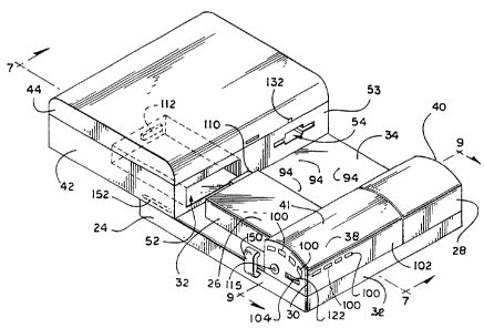
Fig. 2 is a perspective view from a different angle
of the metal-air battery of Fig. 1 disassembled from the
portable computing device.
Fig. 3 is an exploded view of the metal-air battery
of Fig. 1 showing the cell housing, the removable projection
to extending from the housing and the disk access door.
Fig. 4 is a diagrammatic view of barriers defining
the flow path of reactant air beneath the air cathode assemblies
of the metal-air cells that comprise the battery.
Fig. 5 is a top plan view of metal-air cells inside
is the bottom tray of the housing showing the foam sealing pad
(in part) and the interconnection of the battery cells.
Fig. 6 is a bottom plan view of the inner surface
of the top tray of the housing showing the hydrogen vent holes
and the air plenum.
2o Fig. 7 is a side cross sectional view taken along
line 7-7 of Fig. 2 showing the removable projection extending
parallel to and in spaced apart relation from said upper surface
of said housing.
Fig. 8A is a horizontal cross sectional view of the
2s projection, looking down, taken along line 8A-8A of Fig. 7,
showing the projection printed circuit board.
Fig. 8B is a bottom plan view of the metal-air
battery printed circuit board showing the battery connector
and the EEProm.
3o Fig. 9 is a vertical cross sectional view of the
projection and of the battery looking to the rear taken along -
line 9-9 of Fig. 2.
Fig. 10 is a pictorial view of the disk access door
in the open position allowing access to the disk drive of the
3s portable computing device.
W~J 96/07209 PCT/US95/10714
0~~9~T00
Fig. 11 is a side cross sectional view of the door
and of the battery taken along line 11-I I of Fig. 10, showing
the door pivoted down and away from the portable computing
device below the plane extending from the disk drive.
s Fig. 12 is a block diagram of the electrical
connections of circuitry in the projection to the metal-air
battery and to the portable computing device in accordance
with the present invention.
Fig. 13 is a side cross sectional view of the metal
to air battery externally assembled to the portable computing
device taken along line 13-13 of Fig. l, showing the
attachment clip engaged with the portable computing device in
accordance with the present invention.
Fig. 14 is a perspective view of a docking
is platform for used in connection with a portable computing
device to which the battery of the present invention is
externally assembled.
Fig. 15 is a perspective view of an alternate
configuration of a metal-air battery in accordance with the
Zo present invention for external assembly to a portable
computing device.
Detailed Description
25 Referring now in more detail to the drawings, in
which like numerals refer to like parts throughout the several
views, Figs. 1-3 show a battery pack 20 in accordance with the
present invention for external attachment to a conventional
portable computing device 22. This invention will be
3o described with specific reference to a portable computing
device. However, this invention should be understood as
applicable to other portable electronic devices with a battery
compartment therein.
The battery pack 20 comprises three main
3s elements, a cell housing 24, a projection assembly 26 and a
WO 96/07209
PCT/US95/10714
8
disk access door 28. The battery housing 24 forms the base of
the battery pack 20 with the projection assembly 26 and the
disk access door 28 removably mounted to an upper surface 34
of the battery housing 24 along a front edge 36.
s The projection assembly 26 further comprises an
air plenum section 30 and a plug extension section 32. An
upper surface 38 of the air plenum section 30 and an upper
surface 40 of the disk access door 28 together form a palm
rest 41 for use in connection with the portable computing
to device 22.
The conventional portable computing device 22
comprises a base 42 and a hinged display 44 which forms a
cover. The base 42 includes a surface mounted keyboard 48
and track ball 50. The base 42 further includes an internal
Is battery compartment 52 and an internal floppy disk drive 54,
which both open at a front wall 53 of the base 42. The hinged
display 44 of the portable computing device 22 includes a
display screen 46.
As described in more detail below, and shown in
Zo Fig. 2, the battery pack 20 is assembled to the computing
device 22 by aligning the plug extension section 32 with the
battery compartment 52 and sliding the battery pack 20 toward
the front wall 53 of the portable computing device 22.
Turning now in more detail to the elements of the
2s battery pack 20, the cell housing 24 (shown in Figs. 3-7)
comprises a bottom tray 56 and a top tray 58, which may be
cast or injection molded plastic. As shown ~ in Fig. 4, spacer
barriers 60 are each 0.090 inch in height and disposed along
an inner surface 62 of the bottom tray 56 to create a reactant
3o air pathway 63 between the inner surface 62 and a plurality of
metal-air battery cells 64 (shown in Fig. 5).
The preferred embodiment of this invention will
be described with specific reference to metal-air battery cells.
Metal-air battery cells are preferred due to their relatively
3s high energy density. Metal-air batteries have a relatively high
W O 96/07209 __
PCT/US95/10714
9
energy density because they utilize oxygen from ambient air as
a reactant in the electrochemical reaction rather than a heavier
material, such as a metal oxide or other depolarizable metallic
composition. However, this invention should be understood as
s applicable to other types of battery cells. Those skilled in the
art will understand that the reactant air pathways and
associated components for providing an air flow to the metal-
air cells are not necessary if the battery cells do not use
oxygen from ambient air as a reactant.
to The spacer barriers 60 are arranged such that the
reactant air pathway 63 does not have areas of static air and
such that the velocity of all the air in the reactant air pathway
63 is approximately the same. More particularly, a spacer
barrier 60a separates an air inlet 65 of the reactant air
is pathway 63 from an air outlet 66. Spacer barrier 60a is L-
shaped and forms an L-shaped inlet channel 67 in the reactant
air pathway 63 that extends rearwardly from the air inlet 65 at
the front edge 36 and then parallel to a back edge 68. A
spacer barrier 60b is disposed in the inlet channel 67 to
2o prevent a static air pocket in a corner 69. Three U-shaped
spacer barriers, 60c, 60d and 60e are disposed in alternating
orientation for receiving air flow from the inlet channel 67.
An elongated spacer barrier is disposed between the arms of
each U-shaped spacer barrier to create a serpentine air flow
Zs from the inlet channel 67 to the air outlet 66. In the case of
the U-shaped spacer barrier 60c, the elongated spacer barrier
is formed by the arm of the L-shaped spacer barrier 60a that
is parallel to the back edge 68. For the remaining U-shaped
spacer barriers 60d and 60e, the elongated spacer barriers are
3o separate spacer barriers 60f.
Each metal-air cell 64 includes an air permeable
cathode and a metallic anode separated by an aqueous
electrolyte (not shown). The metal-air cells further comprise
hydrogen vents 71 disposed opposite of the air permeable
CA 02198700 2000-05-23
cathode. The hydrogen vents 71 discharge hydrogen generated by the metal air
cells
during recharging.
A flap valve 45 is mounted over each hydrogen vent 71 to prevent air and
other gasses from entering the cells 64 via the hydrogen vents 71 while still
allowing
5 hydrogen to escape. The flap valve 45 comprises a strip of thin, flexible,
plastic material
that is deformed under pressure but that resiliently returns to its original
shape and
position in the absence of such pressure. A portion 61 of the flap valve 45 is
secured to
the top of the cell 64 adjacent to the vent 71, preferably by means of hot
melt adhesive.
The unsecured portion of the flap valve 45 extends laterally from the secured
portion 61
10 to cover the adj acent vent 71. In its undeformed position, the flap valve
45 seals over the
vent 71 against the top of the cell 64 to prevent air and other gasses from
entering the cell
64. When hydrogen is generated in the cell 64, the pressure causes the thin
strip of
flexible material to deform away from the vent 71 and thus allows the hydrogen
to escape
through the vent 71. Upon the release of the hydrogen, the pressure in the
cell returns
to normal and the flap valve reseals over the hydrogen vent 71.
The anode of a metal-air cell is made from metals which can be oxidized
during discharge in a metal-air cell to produce electrical energy. Such metals
include
lead, zinc, iron, cadmium, aluminum and magnesium. Zinc is the preferred metal
for the
anode because of its availability, energy density, safety and relatively low
cost. KOH is
the preferred electrolyte. A suitable electrolyte is an aqueous electrolyte
including group
I metal hydroxides such as LiOH, NaOH, KOH, CsOH or the like. The preferred
metal-
air cell is described in U.S. Patent No. 5,306,579, which may be referred to
for further
details.
The metal-air battery 64 are disposed upon the spacer
cells
barriers 60 as shown in Fig. with the air cathode open
S,
to the reactant air pathways 63. The metal-air cells 64
WO 96/07309 PCTlUS95/10714
I1
are held in place by stops 55 which extend inward from the
front inner side 57 of the bottom tray 56 and posts 70 which
extend upward from the bottom tray 56.
The metal-air cells 64 each include a positive
s electrode 80 and a negative electrode 81, which are electrically
connected in series by a plurality of strips 72. A pair of
terminals, negative terminal 73 of the cell 64b and a positive
terminal 74 of the cell 64c, provide the power output of the
battery. The electrically connected metal-air cells 64 together
io form a metal air battery 82, which is wired to a battery supply
connector 75. The metal-air battery of the preferred
embodiment has eight (8) metal-air cells which generate 1 volt
each, for a total of 8 volts. A center tap 87 is separately wired
from a central strip 91 to the battery supply connector 75. As
is explained below, the center tap 87 allows the cells 64 to be
monitored as two groups during recharging.
The battery supply connector 75 is mounted on a
printed circuit board 83 which also holds an EEProm 89 for
storing the state of the metal-air battery 82 when it is
Zo disconnected from the portable computing device 22. The
printed circuit board 83 is shown in Fig. 8B.
A foam sealing pad 76 is disposed over the metal-
air battery cells 64 and covers the area of the bottom tray 56
except for the air inlet 65 and the air outlet 66 of the reactant
2s air pathway 63. An opening 77, however, is provided in the
foam sealing pad 76 directly above each hydrogen vent 71 of
the metal-air battery cells 64. The pad 76 prevents air leakage
from the reactant air flow below the cells into the space above
the cells, and provides a gasket to seal around the vents 71
3o when the top 58 is installed. Alternately, the spaces between
the cells and the spaces between the cells and the housing can
be sealed by beads of hot melt adhesive.
The bottom tray 56 includes an extended lip 78
around its sides that mates with an indentation 79 on the top
3s tray 58 to form a moisture seal. The seal is necessary to help
WO 96/0?209 PCT/US95/10714
i
o z ~ 98 goo
12
prevent water loss from the cells, which would result in
decreased battery output and life time.
A hollow protrusion 84 integrally molded with
the top tray 58 extends upward from the upper surface 34 of
s the top tray 58. The protrusion 84 defines an air inlet
ventilation hole 85 and an air outlet ventilation hole 86 in a
rear wall of the protrusion 84, spaced a short distance apart. A
fan 88 is positioned across the interior of the protrusion 84,
dividing it into an inlet air plenum 90a and an outlet air
to plenum 90b, as best shown in Figs. 8A and 9. The fan 88 is
bounded by a gasket 51 which seals inlet plenum 90a from
outlet plenum 90b except for the flow of air directed by the
fan 88. When the metal-air battery 82 is in use, the ventilation
holes are open to allow ambient air to flow into the housing 24
Is and thus through the reactant air pathway 63 and across the air
cathodes of the metal-air cells 64.
As shown in Figs. 3 and 6, the top tray 58 of the
housing 24 defines a plurality of hydrogen vent holes 94. The
hydrogen vent holes 94 correspond to the hydrogen vents 71
Zo of the metal-air cells 64. The hydrogen vent holes 94,
however, are slightly offset from the hydrogen vents 71 such
that an object pushed through a hydrogen vent hole 94 of the
top tray 58 will not enter the corresponding hydrogen vent 71
and damage a metal-air cell.
2s A boss 95 extends from the top tray 58 around
each hydrogen vent hole 94. Each boss 95 is sized to
encompass the corresponding hydrogen vent 71 and the
opening 77 in the foam sealing pad 76 directly above such
hydrogen vent of the battery cells 64. The boss 95 allows
3o hydrogen to vent outside of the housing 24 by way of a
hydrogen vent hole 94 while sealing against the foam sealing
pad 76 to prevent hydrogen from escaping into other spaces of
the housing 24. Thus, hydrogen released by a cell 64 enters
the area surrounded by the boss 95 and then exits the cell
3s housing 24 through the vent hole 94. From the vent hole 9.~,
W,O 96/07209 PCT/US95/10714
" 9
13 0219700
the released hydrogen enters into a space 47 formed between
the upper surface 34 of the cell housing 24 and the bottom of
the portable computing device 22. The housing 24 and the
computer 22 are held in spaced apart relation by a plurality of
s legs 49 of the computer 22. If a computer does not include
legs 49, a plurality of bosses (not shown) may be provided on
the upper surface 34 of the housing 24 such that the hydrogen
may vent out from under the computer between the bosses.
The air plenum section 30 of the projection
to assembly 26 includes a downwardly opening cavity 96 having
the same horizontal cross sectional shape as the protrusion 84
of the housing 24. The projection assembly 26 may be
installed in the position shown in Fig. 2 by placing the cavity
96 over the protrusion 84. As shown in Fig. 7, a space 98
is remains at the top of the cavity 96 above the protrusion 84 and
under an upper surface 38 when the air plenum section 30 is
installed. The space is open to ambient air by way of openings
100 in a front wall 102 and a side wall 104 of the air plenum
section 30. A plurality of supports 99 provide support for the
Zo upper surface 38 such that it may be used as a palm rest 41.
A pair of thumbscrews 122 are . mounted in
recesses 123 on the air plenum section 30 for securing the
projection assembly 26 to the cell housing 24. The
thumbscrews 122 extend downward toward a pair of threaded
Zs retainers 124 formed on the top 58 of the cell housing 24.
The air plenum section 30 is aligned for attachment with the
cell housing 24 by a pair of locator pins (not shown) that
extend downward toward a pair of openings 125.
The plug extension 32 of the projection assembly
30 26 is a hollow box fixed at an open end thereof to the air
plenum section 30. The plug extension 32 extends to the rear
spaced a short distance above the top 58 of the cell housing 24.
The plug extension 32 includes a printed circuit board 108, a
device supply connector 110, and a solenoid valve assembly
3s 118, as will be described in detail below. A block diagram
WO 96/07.209 PCT/US95/10714
0219~~00
14
detailing the electrical connections of the projection assembly
26 to the metal-air battery 82 and to the portable computing
device 22 is shown by Fig. 12.
A battery connector 106 is provided in the air
s plenum section 30 of the projection assembly 26 for
engagement with the battery supply connector 75 of the
housing 24. The battery connector 106 is electrically wired to
the projection printed circuit board 108 in the plug extension
32 of the projection assembly 26. An up converter 114 is
to provided on the projection printed circuit board 108 to
convert the 8 volts of the metal-air battery to the I2 volts
needed to operate the portable computing device 22.
The projection printed circuit board 108 is
electrically connected to the device supply connector 110 as
is shown in Fig. 3. The device supply connector 110 engages a
device connector 112 in the battery compartment 52 of the
computer 22 when the battery pack 20 is assembled to the
computer 22. The device connector 112 is electrically
connected to the portable computing device 22. Thus, power
Zo is supplied to the portable computing device 22 through the
device connector 112.
A microprocessor 113 is provided on the
projection printed circuit board 108 for processing signals
from the battery and from the portable computing device 22.
2s Signals are received and sent between the portable computing
device 22 and the microprocessor 113 through the device
connector 112.
As show particularly in Figs. 8A and 12, the
projection printed circuit board 108 is further electrically
3o connected to a 12 volt accessory jack 115, a recharge jack 116
and the solenoid 118. The accessory jack 115 is provided in a
side wall 104 of the air plenum section 30 for powering an
electronic device such as a cellular telephone. The
microprocessor 113 disables the accessory jack 11 S while the
3s portable computing device 22 is drawing significant power to
WO 96/07209 PCT/US95I10714
0298700
prevent interference with the operation of the portable
computing device 22. For example, the jack 115 may be
disabled when the computer 22 exits a "sleep" state and
becomes active.
s The recharge jack 116 is disposed in a wall of the
plug extension 32 and electrically connected to the metal-air
battery 82 through the projection printed circuit board 108. A
recharger (not shown) may be plugged into the jack 116 when
the battery 20 is removed from the computer 22. It will be
to appreciated by those skilled in the art, however, that the
recharge jack 116 may be located in an exterior wall of the
projection assembly 30 such that it remains exposed when the
battery pack 20 is assembled to the computing device 22. In
such a configuration, disassembly would not be necessary to
Is plug the recharger into the jack 116. Additionally, a device
recharge jack (not shown) of the portable computing device 22
may be used as the recharge jack 116 if compatible with the
battery pack 20.
The solenoid 118 has dual piston rods extending
Zo toward the protrusion 84, bearing an inlet seal pad 120 and an
outlet seal pad 121. When the piston rods retract and extend,
the inlet pad 120 opens and closes the air inlet ventilation hole
85 and the outlet pad 121 opens and closes the air outlet
ventilation hole 86. Thus, upon receipt of a power on signal
2s from the computing device 22, the microprocessor 113
energizes the solenoid 118 to open the air ventilation holes.
As shown by Figs. 10-11, the disk access door 28
is pivotally mounted to the cell housing 24 by a pair of U-
shaped hinges I34 having an open end facing the disk access
3o door 28. The U-shaped hinges 134 are spaced apart by a pair
of rods 135 which are pivotally mounted to the disk access
door 28 and to the cell housing 24. A first rod 135a is secured
to an inner surface 137 of the disk access door 28 by snapping
into a first pair of retainers 136. A second rod 135b is
3s secured to the upper surface 34 of the cell housing 24 by a
WO 96/07209 ~ PCT/US95/10714
16
second pair of retainers 138 molded on the housing 24, as
shown in Fig. 3.
The disk access door 28 includes an exposed side
wall 126 and an interior wall 128. The exposed wall extends
s from the upper surface 40 to the cell housing 24. The interior
wall 128 extends only a portion of the distance from the upper
surface 40 to the cell housing 24. A cutout 130 is provided on
the upper surface 40 so that the door does not cover a
microphone 132 on the hinged display 44 of the portable
to computing device.
As a result of the U-shaped hinges 134, the disk
access door 28 pivots around two axes and opens to a position
down and away from the portable computing device below a
plane extending from the disk drive 54. Thus a removable
is disk 139 may be inserted into the disk drive 54 without
removing the battery pack 20 from the portable computing
device.
The assembled battery pack 20 is secured to the
portable computing device 22 by the insertion of the extension
20 32 into the battery compartment 52 and by two set of clips. A
first set of clips 142 are pivotally attached to the backside 140
of the cell housing 24 as shown in Figs. 3 and 13: The clips
142 each comprise an elongated member 144 having a curved
extension 143 opposite the pivoting end for engagement with a
2s mating opening 141 of the computing device 22. A beveled
hook 145 is provided on the cell housing 24 for securing each
clip 142 in its engaged position.
The clips 142 are laterally biased toward the hook
145 by first spring 146 mounted on the clip's pivot axle 129
so and pivotally biased toward the hook 145 by a second spring
147. The second spring 147 is also mounted on the pivot axle
129 and includes an extending straight end that presses against
the clip 142 in a conventional manner. A handle 148 is
provided on each clip 142 for positioning the clip 142.
CA 02198700 2000-05-23
17
Pressure on the clip 142 causes it to slide past the beveled hook 145 and to
snap in place
under the force of the spring 146.
A second pair of upwardly extending clips 150 is attached to the cell housing
24 in a stationary position. When the battery pack 20 is assembled to the
computing
device 22, each stationary clip 150 slidingly engages a boss 152 on the base
42 of the
computing device 22 near the front wall 53. Thus, the computing device 22 is
secured at
the front, back and sides to the battery pack 20.
When the portable computing device 22 is to be operated, the user opens the
hinged display 44 and turns on the portable computing device 22. The portable
computing
device 22 sends a signal to the battery pack 20 through the device connector
112. The
signal is received by the microprocessor 113 which energizes the fan 88 and
the solenoid
188, which retracts the pads 120 and 121 from the ventilation openings 85 and
86,
respectively.
Air enters the hollow space 98 through openings 100 and as shown
particularly in Fig. 9, is drawn into the air plenum 90 through the air inlet
ventilation
opening 85 by the fan 88. Next, the air flows downward to air inlet 65 and
then into the
reactant air pathway 63. In the reactant air pathway the oxygen from the
ambient air is
converted at the cathode to hydroxide ions which react with the anode to
release water and
electrons to provide electrical energy. The air then flows to the air outlet
66 of the
reactant air pathway 63 and upward toward the fan. A portion of the reactant
air is then
exchanged for fresh ambient air and the remaining portion is recirculated as
disclosed in
Canadian Patent File No. 2,161,668 which may be referred to for further
details.
The eight metal-air cells 64 generate 8 volts of electrical energy, which flow
to the projection printed circuit board 108 via the battery supply connector
75. At the
projection printed circuit board 108, the voltage is increased to 12 volts by
the up-
converter 114. From the up-converter 114, the 12 volt electrical energy flows
to the
CA 02198700 2000-05-23
18
portable computing device 22 via the device connector 112.
The user can monitor the charge status of the metal-air battery 82 directly
from the display 46 as shown in Fig. 1. The charge status is preferably
displayed to the
user as a level gauge 133 by the portable computing device 22.
To recharge the metal-air battery 82, the battery pack 20 is disassembled
from the portable computing device 22 to expose the recharge j ack 116.
Disassembly is
accomplished by disengaging the clips 142 from the mating openings 141 of the
computing
device 22 and sliding the battery pack 20 away from the front wall 53 of the
computing
device 22. The clips 142 must be moved sideways against the spring 146 to
release them
from the hooks 145 and then rotated out of the openings 142.
The metal-air battery 82 is recharged by connecting a recharger to the
recharge jack 166. The electrical energy flows from the recharge jack 166 to
the metal-air
battery 82 via the projection printed circuit board 108. At the metal-air
battery 82, the
electrical energy is applied between the anode and cathode of the cells 64
which reverses
the discharge electrochemical reaction. The battery 82 may be charged during
operation
of the computer provided the recharge jack 166 is accessible and the recharger
is powerful
enough for both tasks.
The hydrogen generated during recharging is vented from the cell housing
24 through the vents 94 to the space 47 and then generally to the atmosphere.
A catalyst
(not shown) may be provided in the space 47 and/or in the air flow
path 63 for catalyzing a recombination of the generated hydrogen that might be
present
with oxygen. A thermocouple (not shown) or a thermistor (also not shown) may
be
used in conjunction with the catalyst to detect high concentrations of
hydrogen gas in
WO 96/07209 PCT/US95/10714
19
the space 47 by the temperature of the catalyst. The fan 88
could be configured to direct a flow of air into the spaces 47
and 63 if such a high concentration of hydrogen is detected.
Alternatively, the fan 88 could be configured to direct a flow
s of air into the spaces 47 and 63 periodically during recharging
as a safeguard.
During recharge, the microprocessor 113
sequentially monitors the two (2) groups of cells on either side
of the center tap 87 according to a time based sequence. More
io particularly, the microprocessor 113 monitors the center tap
87 and the terminals 73 and 74 of the metal-air battery 82 via
selection circuitry which is controlled by a first and a second
set of control signals. The first set of control signals causes
the selection circuitry to sequentially connect the voltage of the
is groups of the cells to a data input of the microprocessor 113 in
accordance with an iterative time based sequence. To avoid
needless accumulation of data and to utilize less memory, the
microprocessor 113 implements a predetermined time delay
between successive iterations of the time based sequence.
2o Preferably, the time base sequence is sequential with respect to
the order of the groups of cells. When the microprocessor
113 has collected charging data that indicates a predetermined
charge cutoff limit has been reached by one of the groups, the
microprocessor 113 causes the switching circuit to break the
is electrical connection between the battery 82 and the recharge
power source.
As shown in Fig. 14, a docking platform 160 is
provided for situations where a docking device (not shown)
will be connected to the portable computing device 22. Use of
3o the docking platform is preferred in docking situations because
an unsupported docking device may damage the fragile
connectors of the docking device or of the computer 22.
To allow attachment of the docking device, the
pivotal clips 142 must be disengaged from the openings 141 of
3s the portable computing device 22. The normal upstanding
WO 96/07209 PCT/US95/10714
a~
position of the clips 142 discourages attachment of the docking
device without first installing the platform 160. A pair of
bosses 166 are provided on the docking platform 160 to
facilitate alignment of the docking device.
s The docking platform 160 includes a pair of
indentations 164 for receiving the hooks 145 and a pair of
openings 162 for retaining the pivotal clips 142 below a plane
of the upper surface 34 of the cell housing. The docking
platform 160 is sized such that it has the same height as the cell
to housing 24. Thus, the docking device may be attached to the
portable computing device 22 as if the battery pack 20 was
non-existent.
An alternative embodiment of the present
invention is shown in Fig. 15 as a battery pack 20'. The
is battery pack 20' is for use in connection with a portable
computing device 22' of an alternative configuration in which
the battery compartment 52' is open to the bottom of the
portable computing device 22'. With such a configuration,
there is no need for a projection assembly that extends in a
Zo spaced apart relation from the battery pack.
In this embodiment, a projection 26' extends
upward from a cell housing 24' under the portable computing
device 22'. Thus, neither the cell housing 24' nor the
projection 26' extends out from under the portable computing
2s device 22'. A palm rest is not shown but could be attached to
the cell housing 24'.
The battery pack 20' operates in the same manner
as the battery pack 20. Thus, ambient air enters openings 100'
and flows toward the ventilation openings (not shown). When
3o in operation, the solenoid 118' is energized and the pads 120'
and 121' are retracted from the ventilation openings such that
air enters the reactant air pathway (not shown). Power from a
metal-air battery 82' is supplied to the portable computing
device 22' through a device connector 110', which is
WO 96/07209 PCT/US95/10714
~r
2I
electrically connected to a projection printed circuit board
108' that is in electrical contact with the metal-air battery 82'.
From the foregoing description of the preferred
embodiments and the several alternatives, other alternative
s constructions of the present invention may suggest themselves
to those skilled in the an. Therefore, the scope of the present
invention is to be limited only by the claims below and
equivalents thereof.