Language selection

Search

Patent 2199071 Summary

Third-party information liability

Some of the information on this Web page has been provided by external sources. The Government of Canada is not responsible for the accuracy, reliability or currency of the information supplied by external sources. Users wishing to rely upon this information should consult directly with the source of the information. Content provided by external sources is not subject to official languages, privacy and accessibility requirements.

Claims and Abstract availability

Any discrepancies in the text and image of the Claims and Abstract are due to differing posting times. Text of the Claims and Abstract are posted:

  • At the time the application is open to public inspection;
  • At the time of issue of the patent (grant).
(12) Patent: (11) CA 2199071
(54) English Title: ORBITAL LATHE
(54) French Title: TOUR ORBITAL
Status: Expired
Bibliographic Data
(51) International Patent Classification (IPC):
  • B23B 5/32 (2006.01)
  • B23B 3/26 (2006.01)
(72) Inventors :
  • LEFEBVRE, RICHARD (Canada)
(73) Owners :
  • LEFEBVRE, RICHARD (Canada)
(71) Applicants :
  • LEFEBVRE, RICHARD (Canada)
(74) Agent: GOWLING WLG (CANADA) LLP
(74) Associate agent:
(45) Issued: 2001-08-07
(22) Filed Date: 1997-03-04
(41) Open to Public Inspection: 1998-09-04
Examination requested: 1997-03-04
Availability of licence: N/A
(25) Language of filing: English

Patent Cooperation Treaty (PCT): No

(30) Application Priority Data: None

Abstracts

English Abstract


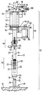
An orbital lathe for resurfacing a fifth wheel kingpin having a
support column insertable between the kingpin and an underlying surface
generally axially aligned with the kingpin. A cutting tool is mounted for
rotation about a pin axis and has a first positioning means for moving the
cutting tool radially relative to the pin axis and a second positioning means
for rotating the cutting tool about an axis generally orthoginal to the pin axis.
Drive means are provided for rotating the cutting tool about the pin axis to
cause the cutting tool to remove material from the kingpin. A transport
mechanism acts between the support column and the positioning means to
move the positioning means and in turn the cutting tool along the pin axis.


French Abstract

Tour orbital permettant de surfacer le tourillon d'une cheville d'attelage dotée d'une colonne d'appui pouvant être insérée entre la cheville d'attelage et une surface sous-jacente généralement alignée dans l'axe de la cheville d'attelage. Un outil de coupe, monté de manière à pouvoir tourner autour d'une cheville d'attelage, comporte un premier dispositif de positionnement pour faire tourner l'outil de coupe radialement par rapport à la cheville d'attelage et un second dispositif de positionnement pour faire tourner l'outil de coupe sur un axe généralement orthogonal par rapport à la cheville d'attelage. Des dispositifs d'entraînement permettent de faire tourner l'outil de coupe autour de la cheville d'attelage pour enlever du matériau de cette dernière. Un mécanisme de transport, entre la colonne d'appui et le dispositif de positionnement, sert à déplacer ce dernier et, ultérieurement, l'outil de coupe le long de l'axe de la cheville d'attelage.

Claims

Note: Claims are shown in the official language in which they were submitted.


I CLAIM

1. An orbital lathe for resurfacing a fifth wheel kingpin, said portable
lathe comprising:

a support column insertable between said kingpin and an underlying
surface, generally axially aligned with said kingpin;
a cutting tool mounted for rotation about a pin axis and having first
positioning means for moving said cutting tool at least and radially relative
to said pin axis and second positioning means for rotating said cutting tool
about an axis generally orthogonal to said pin axis;
drive means for rotating said cutting tool about said pin axis to cause
said cutting tool to remove material from said kingpin; and,
a transport mechanism acting between said support column and said
positioning means for moving said positioning means and in turn said
cutting tool along said pin axis.

2. An orbital lathe as claimed in claim 1 wherein:
said support column includes a first part threadedly connected to a
second part to provide length adjustability to said support column;
said support column further includes centering means for engaging
said kingpin to maintain axial alignment between said support column and
said kingpin along said pin axis;
said first and second positioning means are mounted to a drum which
encircles a sleeve extending about said first part of said support column and
bearings are interspersed between said sleeve and said drum to locate said
sleeve relative to said drum and enable said drum to rotate about said sleeve
about said pin axis;
said drive means includes a motor mounted to said sleeve and a
rotational coupling extending between said motor and said drum to cause
said drum to rotate about said sleeve in response to rotational input from said
motor; and,
said transport means is a rack mounted to one of said sleeve and said
first part of said support column which engages a pinion mounted to the
other of said first part of said support column and said sleeve.

2.

3. An orbital lathe as claimed in claim 2 wherein said second part is
supported by a base member;
said base member includes an upwardly extending generally tubular
part having an inwardly bevelled upper edge; and
said second part has a downwardly depending centering plug mounted
to the bottom thereof, said centering plug having a conical tip for registering
with said frustro-conical recess.

Description

Note: Descriptions are shown in the official language in which they were submitted.


0 2 ~ 9 9 0 7

TlTLE. ORBITAL LATHE
INVENTOR: RICHARD LEFEBVRE


FIELD OF THE INVENTION

This invention relates to portable lathes and in particular to orbital
10 lathes for the in situ ma~ hining of fifth wheel kingpins.

BACKGROUND OF THE INVENTION

A trailer in a tractor-trailer combination is connected to the "fifth
wheel" of a tractor by a fifth wheel kingpin. Through continued use, the
kingpin will wear resulting in a decreased diameter and a consequent
~limini~hment of the security of the connection between the tractor and the
trailer.
One method of restoring the diameter of a fifth wheel kingpin is to
build it up by depositing new metal on the surface of the kingpin and
subsequently ma~ hining the build-up kingpin down to its operational size.
Although this could be done by first removing the kingpin from the trailer,
in order to minimi7e downtime, it is preferable to build-up and machine
the kingpin back down to operational size without removal from the trailer
(i.e., "in situ").
It is an object of the present invention to provide a portable orbital
lathe for economical in situ machining of a fifth wheel kingpin.

SUMMARY OF THE INVENTION

An orbital lathe for resurfacing a fifth wheel kingpin, said orbital
lathe comprising:


0 2 t~9 07 ~ 2.

a support column insertable between said kingpin and an underlying
surface, generally axially ~ligne~1 with said kingpin;
a cutting tool mounted for rotation about a pin axis and having first
positioning means for moving said cutting tool at least and radially relative
to said pin axis and second positioning means for rotating said cutting tool
about an axis generally orthogonal to said pin axis;
drive means for rotating said cutting tool about said pin axis to cause
said cutting tool to remove material from said kingpin; and,
a transport n e~ h~nism acting between said support column and said
positioning means for moving said positioning means and in turn said
cutting tool along said pin axis.

DESCRIPTION OF DRAWINGS
Plefelled embo~linlents of the present invention are described below
with reference to the accompanying drawings in which:
Figure 1 is a front elevation of a portable lathe according to the
present invention;
Figure 2 is a front elevation of a sleeve and a first and a second
positioning means according to the present invention;
Figure 3 is a sectional view on line 3-3 of Figure 2 also showing part of
a support column and sleeve according to the present invention.

DETAILED DESCRIPrION OF PREFERRED EMBODIMENTS

~n orbital lathe according to the present invention is generally
identifie~1 by reference 10 in Figure 1. The orbital lathe 10 includes a supportcolumn 12 insertable between a fifth wheel kingpin 14 and an underlying
surface 16 which may for example be the ground or a concrete footing.

The support column should preferably be of adjustable length to
enable secure placement. Any suitable telescoping arrangement may be

O ~ 0 7 ~ 3.

utilized, one such arrangement is generally illustrated at reference 18. The
support column is made up of a first part 20 which is threadedly connected
to a second part 22. The second part 22 has a threaded collar 23 welded to its
upper end to engage a threaded end 21 of the first part 20. Relative rotation
5 between the first part 20 and the second part 22 will cause relative axial
movement between the first part 20 and second part 22 along a pin axis 24
which is aligned with the kingpin 14 when the portable lathe 10 is installed.
A locking nut 28 is provided above the threaded collar 23 to ~r~v~l.t relative
rotation between the first part 20 and second part 22 once desired length has
10 been att~ine-l

In order to accommodate unevenness in the underlying surface 16, a
base member 26 is provided having an upwardly extpn~ling tubular part 29
having an inwardly bevelled upper edge 32. A downwardly depending
15 centering plug 34 is mounted to the bottom of the second part 22. The
centering plug 34 has a conical projection 36 which registers with the
bevelled upper edge 36 of the tubular part 29. This enables the first part 20
and second party 22 to be aligned with the pin axis 24 without having to be
exactly perpendicular to the underlying surface 16.
Although a conical projection 36 and bevelled upper edge 32 are
shown, other shapes may be selected, for example the centering plug may be
dome-shaped and received in a corresponding curved faced upper edge 32.

An upper end 38 of the first part 20 of the support column 12 is
provided with a conical projection 40 which registers with a recess in the
bottom of the kingpin 14 to act as a centering means to maintain axial
~lignm~nt between the kingpin 14 and the support column 12 along the pin
axis 24.
A cylindrical sleeve 42 extends about the first part 20 of the support
column 12 toward the upper end 38 of the first part 20. The sleeve 42 is
slidable along the first part 20. A transport me~-h~ni~m 44 such as a rack 46
secured to the first part and a pinion secured to the sleeve 42 is provided to

0~19907 1 4-

move the sleeve 42 along the first part 20 of the support column 12. The
transport merh~ni.sm 44 may also include a crank 50 for rotating the pinion
48. The rack and pinion arrangement also prevents relative rotation
between the first part 20 and the sleeve 42. Although a rack and pinion
5 arrangement is shown it is expected that alternate transport means such as
cooperating threads or a hydraulic cylinder may be substitllte-l.

In order to provide a close tolerance sli~ling fft between the first part
20 and the sleeve 42, a guide bushing 43 is threaded into opposite ends of the
10 sleeve 42. The bushing 43 may be made of brass to provide an easily replaced
wear component to avoid wear directly between the ffrst part 20 and sleeve
42.

A cylindrical drum 52 extends about the sleeve 42 toward the upper
15 end 38 of the first part 20 of the support column 12. Suitable bearing such as
tapered bearings 54 extend between the drum 52 and the sleeve 42 to locate
the drum 52 on the sleeve 42 and enable rotation of the drum 52 about the
sleeve 42 about the pin axis 24.

As shown in more detail in Figure 3, the lowermost bearing 54 is
mounted between a flange 45 extending about the second member 42 and a
lower stepped recess 47 in the drum 52. The uppermost bearing 54 is
mounted between an upper stepped recess 49 in the drum 52 and a nut 51
threadedly engaging the sleeve 42. The nut 51 provides a means to adjust
the crush on the bearings 54. A lock-nut 53 is provided about the nut 51. The
lock-nut 53 is provided with an upwardly extending cylindrical lip 55 which
accommodates a seal 57 mounted between the sleeve 42 and the drum 52 to
prevent cuttings and dirt from entering between the drum 52 and the sleeve
42.
Drive means, generally indicated by referellce 56 are provided to cause
the drum 52 to rotate about the sleeve 42. The drive means in~ les a motor
58 secured to a mounting bracket 60 which is rigidly secured to and extends
from the sleeve 42. The drive means 56 further includes a rotational

~ 2 ~9 07 ~ 5-


coupling, generally indicated by reference 62 comprising a drive belt 64
extending about a drive pulley 66 secured to an output shaft 68 of the motor
58 and a driven pulley 70 ext~on~1ing about or secured to the drum 52. The
rotational coupling 62 causes the drum 52 to rotate about the sleeve 42 in
5 response to rotational input from the motor 58. Additional drive and
driven pulleys of different diameters such as illustrated by re~l~l.ces 72 and
74 respectively may be provided to enable various rotational speeds to be
selected for the drum 52.

The above described rotational coupling means is exemplary.
Variations such as chain and sprocket or direct gear drive merh~ni~m~ may
be substituted.

A cutting tool 76 is secured to the drum 52 and is rotatable with the
15 drum 52 about the pin axis 24. The mounting arrangement for the cutting
tool, which is shown in more detail in Figure 2 includes first -positioning
means for moving the cutting tool radially relative to the pin axis 24 in the
direction of arrows 78. The mounting arrangement for the cutting tool 76
includes second positioning means enabling rotation of the cutting tool 76
20 about an axis orthogonal to the pin axis 24 in the direction of arrows 80.

The first positioning means may be a threaded rod 82 which extends
through a block 84 to which the cutting tool 76 is mounted. Preferably the
block 84 is slidably received in a support block 86 for alignn~ent. For example
25 the block 84 and support block may have a matching "dovetail" shaped
tongue and groove arrangement such as commonly referred to as a
"dovetail block". A knurled knob 88 is provided to rotate the threaded rod
82.

The cutting tool 76 is secured to a tool holder 90 which in turn is
secured to the block 84 by hex screws 92. Curved slots 94 are provided in the
tool holder 90 which act in conjunction with the hex screws 92 as the second
positioning means to allow rotation of the cutting tool 76 in the direction of
arrows 80 in Figure 1. Rotation of the cutting tool above and below a

~2 ~9~71 6.


generally horizontal axis is desirable to enable cutting of both an upper and a
lower radius on the kingpin 14. Preferably the cutting tool 76 should be
rotatable to a generally vertical position should it prove necessary to cut the
weld securing the kingpin 14 to the trailer in the event that kingpin
5 replacement rather than resurfacing should prove necessary.

The above description is intended in an illustrative rather than a
restrictive sense. Variations to the exact embodiments described may be
apparent to those skilled in the relevant art without departing from the
10 spirit and scope of the claims set out below. It is inten~ell that any such
variations be deemed within the scope of this patent.

Representative Drawing
A single figure which represents the drawing illustrating the invention.
Administrative Status

For a clearer understanding of the status of the application/patent presented on this page, the site Disclaimer , as well as the definitions for Patent , Administrative Status , Maintenance Fee  and Payment History  should be consulted.

Administrative Status

Title Date
Forecasted Issue Date 2001-08-07
(22) Filed 1997-03-04
Examination Requested 1997-03-04
(41) Open to Public Inspection 1998-09-04
(45) Issued 2001-08-07
Expired 2017-03-06

Abandonment History

There is no abandonment history.

Payment History

Fee Type Anniversary Year Due Date Amount Paid Paid Date
Request for Examination $200.00 1997-03-04
Application Fee $150.00 1997-03-04
Maintenance Fee - Application - New Act 2 1999-03-04 $50.00 1999-03-03
Maintenance Fee - Application - New Act 3 2000-03-06 $50.00 2000-03-03
Maintenance Fee - Application - New Act 4 2001-03-05 $50.00 2001-03-05
Final Fee $150.00 2001-05-08
Maintenance Fee - Patent - New Act 5 2002-03-04 $75.00 2002-03-04
Back Payment of Fees $25.00 2004-01-30
Maintenance Fee - Patent - New Act 6 2003-03-04 $275.00 2004-01-30
Maintenance Fee - Patent - New Act 7 2004-03-04 $100.00 2004-01-30
Maintenance Fee - Patent - New Act 8 2005-03-04 $100.00 2005-03-03
Maintenance Fee - Patent - New Act 9 2006-03-06 $100.00 2006-03-01
Maintenance Fee - Patent - New Act 10 2007-03-05 $125.00 2007-02-14
Maintenance Fee - Patent - New Act 11 2008-03-04 $125.00 2008-03-04
Maintenance Fee - Patent - New Act 12 2009-03-04 $325.00 2009-03-16
Maintenance Fee - Patent - New Act 13 2010-03-04 $125.00 2010-02-22
Maintenance Fee - Patent - New Act 14 2011-03-04 $125.00 2011-02-25
Maintenance Fee - Patent - New Act 15 2012-03-05 $225.00 2012-03-02
Maintenance Fee - Patent - New Act 16 2013-03-04 $225.00 2013-03-01
Maintenance Fee - Patent - New Act 17 2014-03-04 $225.00 2014-02-27
Maintenance Fee - Patent - New Act 18 2015-03-04 $225.00 2015-02-23
Maintenance Fee - Patent - New Act 19 2016-03-04 $225.00 2016-02-08
Owners on Record

Note: Records showing the ownership history in alphabetical order.

Current Owners on Record
LEFEBVRE, RICHARD
Past Owners on Record
None
Past Owners that do not appear in the "Owners on Record" listing will appear in other documentation within the application.
Documents

To view selected files, please enter reCAPTCHA code :


To view images, click a link in the Document Description column. To download the documents, select one or more checkboxes in the first column and then click the "Download Selected in PDF format (Zip Archive)" or the "Download Selected as Single PDF" button.

List of published and non-published patent-specific documents on the CPD .

If you have any difficulty accessing content, you can call the Client Service Centre at 1-866-997-1936 or send them an e-mail at CIPO Client Service Centre.


Document
Description 
Date
(yyyy-mm-dd) 
Number of pages   Size of Image (KB) 
Cover Page 1998-09-22 1 41
Abstract 1997-03-04 1 21
Description 1997-03-04 6 269
Claims 1997-03-04 2 67
Drawings 1997-03-04 3 41
Drawings 2000-08-04 2 39
Representative Drawing 2001-07-31 1 9
Cover Page 2001-07-31 1 36
Fees 2008-03-04 2 68
Prosecution-Amendment 2000-08-04 3 68
Correspondence 2001-05-08 1 31
Correspondence 1999-03-03 1 42
Assignment 1997-03-04 4 128
Fees 1999-03-03 2 127
Fees 2004-01-30 1 32
Fees 2005-03-03 1 32
Correspondence 2008-03-03 1 45
Fees 2010-02-22 1 35
Fees 2009-03-16 1 55
Correspondence 2010-06-10 8 327
Correspondence 2010-06-22 1 15