Note: Descriptions are shown in the official language in which they were submitted.
CA 02199081 1997-03-04
2193081
-
TITLE OF TEIE INVENTION
HAI~TGEE~
BACKG~OUND OF TE~E INVENTION
Field of the Invention
The present invention r~lates to a han~er fol- hangin~ a
garment for storage, and more particularly, it relates to a
hanger applicable to a children's garment.
Description of Related Art
When a children's garment is suspended on a general size
hanger, it can take a long time or the shape of the garment can
be spoiled because the latitudinal length of the hanger is too
large for the children's garment. In view o-f such a problem, a
hanger exclusively for a children's garment is commercially
available.
~owever, a children's garment can be in a variety of sizes,
and a purchased hanger for a children's garment may not suit
the size of a garment to be hung. In addition, when there are
two or more children in a family? hangers with plural
children's sizes are req-lired. ~loreover, it is
disadvantageously n~cessary to purchase a new hanger with a
suitable size in accordance with the growth of a child.
B~IEF SU~lMA~ 0~ TE~E INVENTION
The present invention was devised in view of the
CA 02199081 1997-03-04
. 2ls~nsl
aforementiolled problems, and the object is providing~ a hanger
wllich has loops with a dimension adjustable with the size of a
garment to be hullgr and whicll can b~ hun~ on a high position
even by a child because a distance between the loops and a
suspending part is elollgated by decreasing the dimension of the
loops.
The halig-cr of this invelltioll comprises two loops, each
made from a flexible material, for suspending an object to be
hung; a supporting part for movably supporting loop extensions
made from the flexible material and extended from the loops
between the two loops; and a suspending part linked with one
end of each of the loop extensions projected from the
supporting part, wherein a dimension of the loops is adjustable
by moving the loop extensions in accordance with a distance
1~ between the supporting part and the suspending part.
Accordingly, in the present hanger, when the suspending
part linked with the one ends of the loop extensions is moved
away from the supporting part, the dimension of the loops is
decreased. ~'hen the dimension of the loops is decreased, the
crosswise length of the shoulders of the hanger for suspending
the object is decreased. Thus, the dimension of the shoulders
of the hanger can be adjusted in accordance with the size of
the object to be hung. Furthermore, since the object to be
hung is suspended on the loops, the object can be stably
supported even when the flexible material is a thin wire
CA 02199081 1997-03-04
-- 2199081
because the flexure in the gravitational directioll is small.
In one aspect of the invention, the supporting part
includes a first fixing part for fixing one end of the flexible
material and a presser part for locking movement of the loop
extensions by applying a pressure to the loop extensions, and
the suspending part includes a second fixing part for fi~ing
the other end of the flexible material.
Accordingly in such a case, when the loop extensions are
pressed by the presser part, the loop extensions become
unmovable, resulting in fixing the dimension of the loops.
Therefore, the dimension of the loops cannot be decreased owing
to the weight of the object to be hung during the usage of the
hanger.
In still another aspect of the invention, the suppol~ting
part includes a case separable in the back-and-forth direction
for housing the loop extensiolls and a screw member for fixing
the case, and the loop extensions are pressed through the case
by screwing the screw member.
Accordingly in such a case, the loop extensions are
pinched by the case for housing the loop extensions and pressed
by screwing the screw member, and hence, switching the
adjustment and fixation of the dimension of the loops can be
easily adjusted and fixed. Furthermore, since the movable
parts of the loop extensions are covered with the case, the
2~ loop extensions ~re prevented from coming off from the
CA 02199081 1997-03-04
'" ~19~0~1
supporting part during the movement.
In still allother aspect of the invention, the two loop
extensions cross each other in the supporting part.
Accordingly in such a case, owing to the crossing of the
5 loop extensions, the flexibility in a direction toward the
center of each loop is smaller than in the case where the loop
extensions do not cross each other, resulting in allowing
smooth movement of the loop extensions. Furthermore, when the
crossing point of the loop extensions is disposed in the
vicinity of the presser part or the screw member, the loop
extensions can be pressed without fail.
In still another aspect of the invention, the flexible
material is a wire, and each of the loops is provided with a
hanger supporting mem~er which has a width larger than a
diameter of the wire and a length along the loop, at a portion
for supporting the object to be hung.
Accordingly in such a case, the hanger assisting member
supports, for example, the shoulders of a garment, and hence,
the garment can be stably supported even when the flexible
material is a thin wire.
In still another aspect of the invention, the suspending
part includes a catching part projecting from a rear face of
the suspending part in a reverse L-shape in a sectional view,
and the catching part is able to bend in the back-and-forth
direction owing to a plurality of hinges provided on a rear
CA 02199081 1997-03-04
'~ 219~081
face thereof.
Accordingly in such a case, the catching part can bend in
the back-and-forth direction, and hence, the hanger can be
suspended on a variety of places. Furthermore, when the
catching part is bent toward the outside of the collar of a
suspended garment, the shape of the collar can be prevented
from being spoiled.
In still another aspect of the invention, the suspending
part has a plurality of ribs on a face reverse to a face close
to the supporting part, and the ribs are aligned in a crosswise
direction crossing the back-and-forth direction with a distance
substantially equal to a width of the catching part.
In still another aspect of the invention, the suspending
part has a plurality of ribs on a rear face aligned in a
crosswise direction crossing the back-and-forth direction with
a distance substantially equal to a width of the catching part.
Accordingly in such cases, the top face of the suspending
part of a first hanger is inserted into a space between the
suspending part and the catching part of a second hanger, so
that these hangers can be linhed with each other. At this
point, the base portion, close to the suspending part, of the
catching part of the second hanger is fit between the ribs of
the first hanger, so that the second han8er can be fixed on and
supported by the first hanger. This can stabilize the linkage
2~ between the first hanger and the second hanger.
CA 02199081 1997-03-04
-- 21Y~081
The above and further objects and features uf the
invention will more fully be appdrel1t from the following
detailed description with accompal1~in~ d~awings.
~RIEF DESCRIPTION OF THE SEVERAL VIEWS OF THE DRAWINGS
FIG. l is a perspective view for showing the structure of
a hanger according to a first embodiment of the invention;
FIG. 2 is a front view of the hanger of FIG. l;
FIG. 3 is a right side view of the hanger of FIG. l;
FIG. ~ is a rear side view of the hanger of FIG. l;
FIG. 5 is a sectional view taken on line V-V of FIG. 2;
FIG. 6 is a sectional view tahen on line VI-VI of FIG. 2;
FIG. ~ is a sectional view taken on line VII-VII of FIG.
2;
FIG. ~ is a front view of the hanger of FIG. l with the
crosswise length of a hanging member narrowed;
FIG. ~ is an exploded perspective view of the hanger of
FIG. l;
FIG. l0 is a front view of the hanger of FIG. l from which
a supporting case cover and a fi~ing case cover are removed;
FIG. ll is a perspective view for showing the rear side
structure of the supporting case cover of the l1anger of FIG. l;
FIG. 12 is a perspective view for showing the rear side
structure of the fi~ing case cover of the hanger of FIG. l;
FIG. 13 illustrates usage uf the hanger of FIG. l;
CA 02199081 1997-03-04
- 2193081
FIG. 14 is a front view for showing the structure of a
suspending member o-f a hanger according to a second embodiment
uf the invelltion;
FIG. 15 is a plall view of the suspending membel- of FIG
1~;
FIG. 1~ is a rigl-lt side view of the suspending member of
FIG. 14;
FIG. 17 is a side view for illujtratillg usage of the
hanger of the second embodiment; and
FIG. lS is a perspective view for illustrating the usage
of the hanger of the second embodiment.
DETAILED DESC~IPTION OF TI~E INVENTION
The present invention will now be described in detail with
reference to the accompanying drawings illustrating the
embodiments thereof.
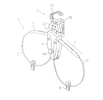
FIG. 1 is a perspective view for showing the structure of
a hanger of the first embodiment, and FIGS. 2, 3 and 4 are a
front view, a right side view and a rear side view thereof,
respectively. FIG. 5 is a sectional view taken on line V-V of
FIG. 2, FIG. G is a sectiollal view taken oll line VI-VI of FIG.
2, ~nd FIG. 7 is a sectional view tal~en on line VII-VII of FIG.
2. As is shown in these drawings, the hanger of this
embodiment comprises a hanging member 1 and a suspending member
2 linked with each other through a nech part 3. The hanging
CA 02199081 1997-03-04
219~()81
member 1 includes two loops 5 aliglled in the latitudinal
direction and a supporting case l for supporting loop
extensiGns 5a extending from the loops 5. On the upper
portions of the loops 5, the neck and shoulders of a garment
are suspended. A skirt, slachs and the like can be clipped
with clipping members ~, which are movable along the loops 5.
The hanger is suspended by han~ing the suspending member 2 on,
for e~ample, a bar in a wardrobe or a lintel. In this hanger,
when the suspending member 2 is moved away from the supporting
case 4, the neck part 3 is elongated, so that the loops 5 are
shortened to narrow the latitudinal length of the hangin~
member 1. FIG. ~ is a front view of the hanger with the
latitudinal length of the hanging member 1 narrowed.
Now, the structure of the han~in~ member 1 will be
described.
FIG. 9 is an exploded perspective view of the hanger of
this embodiment, and FIG. 10 is a front view thereof from which
a supporting case cover 4b and a fixing case cover 22b
described below are removed. The supporting case 4 for
supporting the loops 5 is made of a synthetic resin such as PPF
(polypropylel-le resin includirlg fiber), and is in a shape, in a
front view, having a square upper portion and a narrower and
rounded lower portion. As is shown in FIG. 9, the supporting
case 4 includes a supporting case body 4a having an elevated
2~ outer-periphery fit with a supporting case cover 4b having
CA 02199081 1997-03-04
- 219~1081
substantially the same shape as the supporting case body ~a.
The supporting case body 4a has a rod-like fastening projection
~la at a substalltially center thereof, and thc fastenillg
projection 41a is threaded from its tip to a predetermined
pvsition. A first positioning projection 42a is disposed and
projected below the fastening projection 41a, and second
positioning projections ~3a are aligned and projected in the
latitudinal direction in positions near the center of the
supporting case body ~a and above the fastening projection 41a.
On the outer sides of the second positioning projections 43a,
longitudinally extending guide grooves ~a for fitting the loop
extensions 5a are formed to extend from a substantially center
of the supporting case body 4a to the upper edge thereof.
Latitudinally extending guide grooves ~5a al-e formed so as to
cross the guide grooves 44a and respectively extend from points
close to the second positioning projections ~3a to the right
and left edges of the supporting case body 4a. The
latitùdinally extending guide grooves ~5a have a larger depth
than the longitudinally extending guide grooves 44a, so that
the loop extensions 5a can be stably fit in the guide grooves
44a at crossing points of the guide grooves 4~a and 45a.
Furtl1ermole, on the outer sides of the longitudinally extending
guide grooves ~a, through holes ~6a are formed.
FIG. 11 is a perspective view for showing the rear side
structure of the supporting case cover 4b. The supporting case
CA 02199081 1997-03-04
219~081
cover ~b has a through hole ~lb having a slightly larger
diameter than the fastening projection 41a in a position
colresponding to the fastening projectioll 11a of th~ supporting
case body 4a. In positions corresponding to the first
positioning projection ~2a and the second positioning
projections 43a, a first positioning hole -12b and second
positioning holes ~3b are respectively formed so as to have
slightly larger diameters t11an the corresponding projections.
Also, in positions corresponding to the through holes ~a of
the supporting case body 4a, through holes 46b having
substantially the same diameter as the through holes ~a are
formed.
A wire used as the loops 5 is preferably made from a
material having sufficient strength and appropriate
flexibility, al1d a hard st~l wire (SWIC-~) is used in this
embodiment. As is shown in ~IG. 10, a first wire is wound
around the left positioning projectioll ~3a at its one end, fit
in the left latitudinally e~tending guide groove 45a so as to
extend outward from the upper portion of the supporting case 4,
so that tl1e left loop 5 can be formed outside of the supporting
case ~. Then, after forming the loop 5, the wire is extended
from the lower edge of tlle supporting case ~ to be positioned
on the left side of the first positioning projection ~2a and
the right side of the fastening projection 41a, fit in the
right longitudinally extending guide groove ~a, and projected
-
CA 02199081 1997-03-04
~- ~lY~O~1
upward from the upper edge of the supporting case ~, thereby
forming the loop extension 5a. The other end of the -first wire
is fixed in the suspending m~mbel- ~ d~scribtd btlow. A second
wire is woulld around the right positioning projection ~3a at
its one end and extended latitudinally symm~trically to the
first wire, and fixed in the suspending member 2 at the other
end. The loop extensions 5a cross each other at a point
between the first positioning projection ~2a and the fastening
projection ~la. Either of the wires can be disposed above at
the crossing point, and the first wire is disposed above the
second wire at the crossing point in this embodiment.
The upper portion of each loop 5 extends from the upper
portion of the supporting case ~ in a substantially horizontal
direction, and is provided with a shoulder assisting member 71
of elastomer, thereby forming a shoulder part 7. The shoulder
assisting member 71 has a plurality of hooks for catching the
loop 5 on the rear face, and is provided on the loop 5 with its
one end contained in the supporting case ~. The shoulder
assisting memloer 71 has a shape and dimension appropriate for
supporting the shoulders of a garment and has a suitable
friction coefficient, so that the garment can be sta~ly hung
thereon. Furthermore, the lower portion of each loop 5 is
provided with the clipping member ~ for clipping and suspending
a skirt or the like, so as to be movable along the loop 5.
~hen the loop 5 is changed in its size, the clipping member 6
CA 02199081 1997-03-04
2199081
can be always positioned at the lower portion of the loop 5.
In assembling the hanging member 1 having the
aforementioned structure, the wires art disposed as described
above, the positioning projections 42a and 43a of the
supporting case 4 are respectively fit in the corr~sponding
positioning holes 42b and ~3b as is shown in FIGS. ~ and 11,
and the fastening projection 41a is fit in the through hole
~lb, thereby setting the supporting case cover 4b on the
supporting case body 4a. At this point, collars 47 are
interposed between the fastening projection 41a and the through
hole 41b and between the first positioning projection 42a and
the positioning hole 42b so as to sandwich the loop extensions
5a. Then, a cap nut 48 is screwed on the fastening projection
41a projected through the through hole 41b, and latch pins 49
are inserted into the through holes 46a and ~6b. Thus, the
supporting case cover 4b is fixed on the supporting case body
4a. By screwing tlle cap nut ~8, the supporting case cover ~b
presses the collars ~7, so that the loop extensions 5a around
the fastening projection 41a are pressed by the collars ~7 to
be unmovably locked. When the cap nut 48 is loosened, the loop
extensions 5a become movable. The cap nut 48 has an irregular
periphery so as to be easily turned.
Next, the structure of the suspending member 2 will be
described. The suspending member 2 includes, as is shown in
FIGS. 1 through 8, a clipping part 21 in a U-shape with its
12
CA 02199081 1997-03-04
21~081
operlirlg facing riglltward (ol leftward) as its Uppt'l pOrtiOII alld
a fixing case 22 for fixing the ends of the wires as its lower
portion. The clipping part 21 is provided with a catchin~ part
2~ in a re~erse L-shape, in a side view, on its lower rear
face. The clipping part 21 and the fixil-lg case 22 are made of
a synthetic resin such as PPF, and the catching part 2S is made
of a syntll~tic r~sin such as pulyethylerLe (PE).
The fixing case 22 is in a substantially trapezoidal shape
in a front view, and includes, as is shown in FIG. 9, a fixing
case body 22a having an elevated outer-periphery fit with a
fixing case cover 22b having substantially the same shape as
the fixing case body 22a. The fixing case body 22a is
integrated with the clipping part 21. The fixing case body 22a
is provided with rod-like positioning projections 23a
latitudinally aligned at a substantially c~nter. Below the
positioning projections 23a, longitudinally extending guide
grooves 2~a for fitting the wires are formed to reach the lower
edge of the fixing case body 22a. On the inner sides of the
guide grooves 2la, through holes 25a are latitudinally aligned.
The upper portion of the fixing case body 22a, namely, the
l~wer portion of the clipping part 21, has a larger thichness
by a dimension corresponding to the thickness of the fi~ing
case cover 22b so that projecting in front. At the center of
this thicker portion, an adjusting protrusion 26a having a
2~ predetelmined thickness and extending downward is provided.
CA 02199081 1997-03-04
2lssnsl
Each wire extending upwal~d from the upper edge of the
supporting case -l is, as is shown in FIG. 10, fit in the guide
groove 2~a of the fixing case body 22a and woulld aroulld the
positioning projection 23a at the end so as to be fixed. Thus.
the hanging member 1 and the suspending member 2 are linhed
with each other through the ~qires forming the neck part 3.
FIG. 12 is a perspective view for showing the rear side
structure of the fixing case cover 22b. The fixing case cover
22b has positioning holes 23b having a slightly larger diameter
than the positioning projections 23a of the fixing case body
22a in pOSitiOIIS corresponding to the positioning projections
23a, and also has through holes 2~b having substantially the
same diameter as the through holes 2~a in pOSitiOIlS
corresponding to the through holes 25a. Furthermore, in a
position corresponding to the adjusting protrusion 26a, an
adjusting recess 26b with a depth equal to the height of the
adjusting protrusion 2Ga is formed.
In assembling the suspending member 2 having the
aforementioned structure, as is shown in FIGS. 9 and 12, the
adjusting protrusioll 2Ga and the positiolling projections 23a
are fit in the adjusting recess 26b and the positioning holes
23b, respectively, thereby setting the fixing case cover 22b
the fixing case body 22a. At this point, the front faces of
the fixing case cover 22b and the clipping part 21 are
positioned at the same level. Then, latch pins 2l are inserted
CA 02199081 1997-03-04
.~ 2Issn~l
into the throu~h holes 2~a and 25b, thereby fixing the fi~ing
case cover 22b on the fixing case body 22a.
The catching part 2S disposed on tht lowel- real- face of
the clipping part 22 has, as is shown in FIGS. ~ and 5, groov~s
28a extending latitudillally between the right and left edges of
the rear face of the catching part 28 at a predetelmined
interval in the lollgitudinal directioll. Each of the grooves
2~a has a depth slightly smaller than the thickness in the
back-and-forth direction of the catching part 28, so as to
together work as plural hinges. By allowing the side faces of
the respective grooves 28a to come in contact with or away from
one another, the catching part 2S can be bent in the back-and-
forth direction within a range shown with two-dot chain lines
in FIG. 5. Thus, the catching part 28 can catch ~arious shaped
pl~ces. Furthermore, the lower portion of the catching part 28
has a larger latitudinal dimension than the upper portion
thereof, and is provided with legs 28b, which are covered with
non-slip caps, at the right and left edges. When the catching
part 28 is placed ull, for e.~ample, a table, the legs 28b are in
contact with the table, so that the hanger can be stably
supported.
FIG. 13 is a diagram fol illustratin~ usa~e of the hangel-
having the aforementioned structure. When a children's garment
is to be suspended on the hanger, the cap nut ~8 is loosened by
turning it in the counterclockwise (or clockwise) direction
CA 02199081 1997-03-04
- 219~
first, so that the loop extensiorls 5a become movable. Then,
the fixing case 22 is moved away from or toward the supporting
case 4, so as to elongate or shorten the lleck part 3. Thus,
the dimension of the loops 5, namely, the latitudinal length of
the shoulder parts 7, is adjusted with the size of the
children's garment to be hung. When adjusted, the cap nut 48
is turned in the clockwise (or counterclockwise) directiorl and
locked. Under this condition, for example, a children's skirt
is suspended by clipping it with the clipping members ~, and a
coat is suspended on the shoulder parts 7. Then, with the
supporting case ~ gripped with a hand, a bar 8 is clipped with
the clipping part 21 so as to suspend the hanger thereon. At
tllis point, the nech part 3 has an increased length by the
shortened dimension of the loops, and hence, even a child can
suspend the hanger on the bar ~ at a high position.
In this manller, the dimension of the loops 5 can be
increased or decreased in the present hanger by adjusting the
distance between the fixing case 22 and the supporting case 4,
so that the shoulder parts 7 can be adjusted to have a desired
latitudinal length. After adjusting the latitudinal length of
the shoulder parts 7, the loop extensions 5a are pressed and
locked by USillg the cap nut 48, so as to fix the adjusted
latitudinal length of the shoulder parts 7. In addition, when
a garment to be hung is smaller, the length of the nech part is
adjusted to be longer. This is convenient for a child to
1(~
CA 02199081 1997-03-04
219~081
suspend the hanger on a bar at a high position.
Moreover, in the present hanger, the bottom face of the
fixing case 22 has a shape to lie closely on the top face of
the supporting case 4. Therefore, when the length of the neck
part 3 is minimized, the supporting case ~ and the fixing case
22 are in contact with each other with no gap therebetween. In
such a case, the loops 5 have the maximum dimension, and an
adult's garment can be suspended on the hanger.
Furthermore, since the catching part 28 has a plurality of
hinges on its rear face, it can be bent in the back-and-forth
direction. Therefore, the catching part 2S is applicable to a
wide range of places, and for e.~ample, can catch a grab rail in
a car or can hook on the door lintel. Also, the catching part
2S can bent so as not to touch the collar of a hung garment,
and hence, the shape of the collar is not spoiled.
FIG. 1~ is a front view for showing the structure of a
hanger according to a second embodiment of the invention,
wherein portions e.~cluding a suspending member are omitted.
FIG. 15 is a plan view of the suspending member of FIG. 14. and
FIG. 1~ is a right side view of the suspending member of FIG.
14. This suspending member 2 includes a clipping part 21 iII a
U-sllape Wit~l its Opellillg facirlg riglltward (or leftward) as its
upper portion and a fi~ing case 22 for fi~ing the ends of wires
as its lower portion. On the lower rear face of the clipping
part 21, a catching part 2S in a reverse L-shape in a side view
CA 02199081 1997-03-04
2ls~nsl
~,
is disposed. The upper face of the clipping part 2S is
provided with fixing ribs 201, whicll characteri~e this
embodimerlt.
Each fixing rib 201 has a revel-se L-shape in a side view,
and is formed on tlle upper face of the clipping part 21 so as
to extend toward the real face thereof and project upward and
backward from the clipping part 21. The two fixing ribs 201
are aligned in the latitudinal direction in a front view with a
predetermined distance therebetween. The distance between the
fixing ribs 201 is substantially the same as and preferably
slightly larger than the latitudinal width of the catching part
2~. The remaining structure of this hanger is the same as that
of the first embodiment, and hence, like reference numerals are
used to refer to like elemellts and description is omitt~d.
The hanger of this embodiment can be used in the same
manner as the hanger of the first embodiment, and can attain
the same effects. Moreover, when this hanger is used in the
following manner, a further effect can be attained: FIG. 17 is
a side view for illustrating usage of the hanger of the second
embodiment, and FIG. lS is a perspective view of the hanger in
use, namely, suspending a garment. A first hanger 11 is placed
on a table 13 with the legs 2~b of the catching part ~5 in
contact with the top face of the table 13. The catching part
2~ of a second hanger 12 is caught on the top face of the
2~ clipping part 21 of the first hanger 11, with the clipping part
lS
CA 02199081 1997-03-04
2ls~nsl
21 of the first hanger 11 salldwiched between the clipping part
2~ and the fixing case 22 of the second hanger 12. At this
point, the base portioll of the catching part 2$ of the secolld
hanger 12 is fit and fixed between the fixing ribs 201 of the
first han~er 11.
In this manner, plural l-langers can be linhed with olle
another in the vertical direction. As a result, when a narrow
space for placing the first h~nger is available, other llangers
can be successively placed on the first hanger. As is shown in
FIG. 1~, by suspending garments on these hangers, a plurality
of garments can be suspended in a small space. Moreover, when
no garment is suspended on the hangers as is shown in FIG. 17,
the hangers can be conveniently stored without getting tangled
with one another.
In the second embodiment, two hangers are linhed with each
other, but the number of the hangers is not limited to two.
The hangers can be linked with one another in any number
according to the weights of garments to be hung.
Furthermore, the hanger of the first embodimellt can be
2~ used to be linked with another hanger similarly to the hanger
of the second embodiment. In this case, the clipping part of a
first hanger is inserted into a space between the fixing case
and the catching part of a second hanger, so that the catching
part of the second hanger can be supported by the top face of
the clipping part of the first hanger.
19
CA 02199081 1997-03-04
2199081
In the first and second embodimellts, the wires are used as
the flexible material for th~ loops. which does not limit the
invention. It is possible to adopt any material which has
flexibility sufficient for smoothly elongating or shortening
the loops 5 in accordance with the length change of the nech
part 3 and has a strength sufficient for withstanding the
weight of a garment to be hung. Furthermore, in these
embodiments, the supporting case 4, the fixing case 22, the
clipping part 21 and the catching part 28 are made of the
synthetic resins, which does not limit the invention. It is
possible to adopt any material which is sufficiently light for
use by a child and is sufficiently strong for retaining a
suspended garment.
In this manner, one end of a rlexible material forming a
loop for suspending an object to be hung is linked with a
suspending part in the hanger of this invention. Accordingly,
when the suspending part is moved away from a supporting part,
the dimension of the loop is decreased, so that the latitudinal
length of shoulders of the hanger can be adjusted in accordance
with the size of a garment to be hung. Moreover, when the
dimension of the loop is decreased, the neck part is elongated
conveniel1tly for suspending the hanger at a high positiun.
Also, since a screw member presses a loop e~tension through a
case serving as the supporting part, the loop can be easily
locked and unlocked for the adjustment of the dimension
CA 02199081 1997-03-04
2i9~081
thereof. Furthermore, by providing the loop with a hanger
assisting member, the object to be hung can be stably
suspended. Moreover, since a catching part which Call be freely
bent in the back-and-forth direction is provided, the hanger
can be s~lspended on a variety of places. In addition, by
forming ribs on the suspendin~ part, a plurality of hangers can
be stably linked with one another in the vertical direction.
As this invention may be embodied in several forms Witllout
departing from the spirit of essential characteristics thereof,
1~ the present embodiments are therefore illustrative and not
restrictive, since the scope of the invention is defined by the
appended claims rather than by the description preceding them,
and all changes that fall within metes and bounds of the
claims, or equivalence of such metes and bounds thereof are
therefore intended to be embraced by the claims.