Note: Descriptions are shown in the official language in which they were submitted.
- ~ 21 9qO't5
l DISHWASHER VE~ SYSTE~
2 This invention relates to a vent system Sor dishwashers.
3 T~e invention is particularly suita~le to front-loading
4 dishwashers having a door that hinges up to closed position for
w~hin~ and down to open pOBition for loading a~d unloading.
6 BAcKGRoUND OF THE IN~TION
7 Various venting arrangements have been pro~ided for allowing
8 dishwashers of the above general type to admit dry air and
9 PY~ st moisture-laden air during the qrying cycle of the washer
so as to add to the efficiency o~ the drying operation. Examples
ll are seen in several U.S. patents.
12 Patent No. 3,876,469 to Schi~P shnws a passive ventin~
13 system with an air inlet at the bottom of the door and an air
~4 outlet at the top of the door. A flapper ~alve controls flow of
the air. The door top is considerably enlarged to accommodate
16 the flapper valve and associated control linkage.
17 Pa~ent No. 4,27~,821 to Herbst also shows a passive vent.
18 The air inlet is at the top o~ the door.
l9 Patent No. 3,908,681 to Schimke shows a dynamic venting
~ystem. ~ir is drawn in by a fan near the top of the door and
21 exits through an outlet at the bottom of the door. ~he fan is
22 energized continuo~sly or intermittently during the drying cycle.
23 The fan ducting is always open.
24 Patents Nos. 3,092,122 to Guth and 4,241,158 to Quayle show
other venting arrangemen~s using flapper valves. Quayle also
26 employs a ~an at the rear of the tub which blows air o~er heating
27 elements ~nd into the tub.
28 Other venting configurations using fans are shown in Patent
29 Nos. 3,064 to Given, 3,l30,73 to Jellies, 4,6s1,03G to Yake,
5,076,306 to Suzuki and 5,355,900 to Sakata.
3l SUMM~RY OF THE INvENTION
32 The present invention provides a novel venting arrangement
33 for dishwashers of the front-laading type. Venting means is
2t 99095
1~ carried in the dishwasher door anl ls opera~ive ~ QithQr
2 passively or dynamically draw in dry air during the drying cycle,
3 circulate it through the dishwasher interior so the air will
4 absorb moisture and become saturated, and exhaust the moist or
saturated air. The venting means is further operative to
6 passively vent the dishwasher interior when the washer is not in
7 operation, and to seal off moisture, noise and heat from ~he
8 exterior of the washer during the wash cycle proper.
9 These operations are accomplished by means contained within
~he dishwasher door and arranged to operate quietly and
11 unobtrusively even though the door panels are po~ential sounding
12 boards for any noi~eg generated by the operation o~ door-mounted
13 valves, actuators or other ~r~h~ ms.
14 The invention accomplishes the venting of drying air in a
controlled manner that provides a gradual and quiet transition
16 between open and closed states of a linearly actuated exhaust
17 valve in the exhaust ducting. The valve proper may be a thin,
18 preferably rectangular, molded-plastic, rubber-covered plate
19 mounted within a valve chamber for linear movement, along a path
perpendicular to its face, between fully open and fully closed
21 positions. ~he seating face of the valve is preferably covered
22 with a ~urface of sealing material suc~ as a layer of rubber or
23 rubber-like sheet which co~ers the entire seating face or at
24 least its outer seating portions. The valve or plate is mo~ed
linearly by the actuator in one or the other direction normal to
26 the plane of the plate to advance and retract the plate in
27 relation to a valve port or wash chamber exhaust port, preferably
28 also rectangular, to thereby open and close the valve by opening
29 and closing the flow connection between the ~a~ve port and the
valve chamber. The ~alve port may simply be an opening in the
31 inner li~er of the door, and is preferably ~ramed by a sealing
32 lip against which the val~e plate seats and seals when the ~alve
33 is fully clo~ed. A grill insert may be received in the valve
34 port.
The valve chamber exhausts through exhaust ducting and a
36 vent at the front of the door. Such d~cting may include a pump
37 chamber with which the valYe chamber directly communicates and
- 21 99095
which contains a cross-flow or paddle wheel type blower extending
2 across t~e width o~ the c~mher and whose axis is generally
3 parallel to the spaced inner and outer ~aces of the door.
4 Pre~erably the valve ch~her and pump chamber are of comparable
-dimension along the width of the door, with the valve chamber
6 opening directly into the pump chamber.
7 This exhaust valving and ducting arrangeme~t lends itself
8 to containment within the confines -o~ the door thickness,
9 preferably within a control con~ole section extending acros~ the
top of the door, while providing valved exhau~t ducti~g o~
11 generou~ cross-section.
12 The val~ing and eYh~ t ducting arrange~ent further lends
13 itself to inclusion in a system in which dry air is drawn in to
14 the bottom o~ the warm washing chamber during drying, and
moisture laden air is discharged at the top of the chamber,
16 thereby contri~uting to drying efficiency. This is accomplished
17 simply by combining an inlet for dry air at the door bottom with
18 the above-discussed exhaust ducting and valving arrangement,
l9 which is at the top o~ the door.
BRIEF DESCRIPTION OF THE DRAWINGS
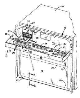
21 In the drawing~, FIG. 1 is an isometric view of part of a
22 dishwasher door, and of an associated molded plastic control
23 console having a front panel to which control elements such as
2~ a molded plastic timer houslng are mounted, the top and side
edges of the front panel being edged with a wide flange to form
26 the top and sides of the console. For purposes of illustration,
27 the console is shown as turned around its lower edge ninety
28 degrees away from other illustrated parts of the dishwasher door,
29 so that the console i8 viewed from above and behind in the
drawing.
31 FIG. 2 is a schematic view on an enlarged scale showing the
32 inner liner or face of the dishwasher door and the ~etal mid-door
33 or liner-of the dishwasher door, such view being taken from the
34 plane~of line 2-2 in FIG. 1; M G. 2 further schematicalIy shows
additional elements as they are viewed from the sa~e plane whe~
_
2 1 99095
the console is turned upwardly g~ degrees a~ nd its lower edge
2 ~rom t~e attitude shown in FIG. 1 ~o its actual attitude in the
3 -installed condition.
4 FIG. 3 is a schematic ~iew on the same scale taken from the
plane of line 3-3 in FIG. 1 and also showing certain additional
6 elements not seen in FIG. 1 but which form part of the dishwasher
7 door and the dishwasher tub bottom.
8 DETAILED DESCRIPTION
9 Re~erring to Fig. 1, a partial dis~washer door assembly 10
has mounted thereto at its upper part a molded plastic control
11 console 12 which has a front wall or panel 14. .The top and side
12 edges of the panel 14 are edged with a relatively wide flange 15
13 forming the ~op and sides of the console. The bo~to~ of the
14 console may comprise a narrow stiffening flange 15a, leaving the
majority of the console bottom open to portions of the dishwasher
16 door interior that are below it.
17 The dishwasher doo~ includes a molded plastic inner door
18 ~ace or liner 16. In a ~ell known manner, when the door is
19 closed, the liner forms a front wall of a dish~asher tub 8 and
~20 clo~es off the tub interior, and when the door is fully open, the
21 liner ~orm~ a generally horizontal door surface over which dish
22 racks or baskets may ~e retracted and advanced between washings
23 in order to remove washed dishes and replace them with a new load
24 of dirty dishes. The tub may comprise a tub bo~tom 11 (FIG. 3)
having a central drain sump portion (not shown) and side, back
26 and top walls (not ~hown) which, together with the door, ~orm a
27 wash chamber when the door is closed. The tu~ construction may
28 be generally as shown in U.S. Patent 4,940,298 to common
29 assignee,' the disclosure of which is incorporated herein by
re~erence.
In the particular device illu~trated, a metal mid-door or -
-32 panel 18 is spaced slightly in ~ront of the inner door liner 16 -
33 by s~ouldered spacers 17 (FIGS. 1, 3) ~hich ~rictionally engage
34 registering openings or holes in the panel 18. The panel 18 may
be forméd with a shoulder 21 so that the panel is closer to the
- - 21-9~095
1 front of the door at the lower portions of the door~than it is
2 at the upper portions of the door. The inner door ~ace or liner
3 16 may have a similar shoulder (not seen) 50 that the two
4 elements are spaced the same distance apart throughout most of
their area~, both at the top and bottom parts of the door.
6 The front of the door may include a metal liner 20 which is
7 a ~ront or outer panel forming part of the face of the door and
8 ext~n~ing from the door bottom to the bottom o~ the console 12.
9 The top of panel 20 may be in the same plane as the front wall
14 o~ the in~talled console, the two elements simply forming a
11 straight joint or seam at their abutting edges.
12 Since the elements 16 and 18 are closer to the plane of the
13 front o~ the door at bottom portions of the door than at top
14 portions of the doo~, the thickness of the door, acro~s the
majority of its width, is greater at its top portions than at its
16 bottom portions, as reflected in the fact that the elements 16
17 and 18, as seen in FIG. 2, are further from the console front
18 wall 14 than these elements, as seen in FIG. 3, are from the
19 front panel 20
The control console may contain vario~s elements relat~d to
21 control and manipulation of the dishwasher, for example, molded
22 brackets 23 ~or mo~nting a timer ho~sing (not ~hown) and a molded
23 ~ramed handle opening 24 for allowing the door to be grasped from
24 the exterior or front when it is to be opened. This handle
opening may also function as an air intake to admit am~ient air
26 to the interior of the console 12 from whence it may be drawn
27 into the washer interior as described below. Alternatively, a
28 separate intake opening (not shown) may be provided in the front
29 panel 20 or elsewhere on the front o~ the door.
According to the present invention, an exhaust system i~
3i provided'in association with the dishwasher door. This system
32 includes a val~e port o~ wash chamber exhaust port 22 (FIG. 2)
33 opening through the inner face of the door from the interior of
34 the wash chamber into a vapor chamber or valve ~h~her 28 within
3S the door. This wash chamber exhaust port may be pro~ided with
36 a suitable molded plastic grille insert 27, (~hown in PIG 1 but
37 not in FIG. 2).
- ;~1 79r,95
1As seen in FIG. 2, the val~e ch~ ~er 28 may be relati~ely
2 shallow as compared with ~he overall thicknes~ of the console 12.
3 Associated with the valve cha~ber is a valve member 30 in the
4 ~orm of a plate which is mounted for linear movement normal to
its p~ane and to the plane of the dishwa~er door, and is
6 closable aga~nst the exhaust port 22. The exhaust port 22 is
7 pre~erably provided with an integra~ rim which receives a rubber
8 sealing lip or gas~et 35, as shown, and the plate-shaped valve
9 member 30 is provided, as shown, with a face sheet of rubber 39
or rubber-like material which close~ against s~ch sealing lip.
11As best seen in FIG. 2, on the side of the valve ~h~h~ 28
12 closest to the front of the dishwasher, the valve member 30 may
13 have a cen~ral stem ~0 which exte~ds through a wall 31 of the
14 valve c~amber a~d is associated with a suitable ~inear actuator
32. It is preferred that such actuator 32 be one of the type
16 known as wax actuators which have the characteristic of imparting
17 relatively gradual ax~al movement to an element such a~ the
18 illustrated valve stem. Eltek of Italy makes suitable actuators.
19 The actuator i~ concentrically aligned with the valve 30. The
imparted movement is back and forth in opposed axial directions
21 when the actuator is respectively electrically heated above
22 am~ient temperature or allowed to cool back down to ambient
23 temperature. The valve member i5 pre~erably normally in closed
24 position, so that it gently and quietly opens as the actuator is
heated and closes as the actuator is allowed to cool. ln a known
2 6 ~nner, the actuator uses heated expanding wax to produce a
27 linear act~ation stroke in the opening direction. As the wax is
28 allowed to cool, an internal spring (not shown) returns the
29 act~ator to its original position to there~y close the valve.
As will' be unde~stood from the drawi~gs and the above
31 description, the path on which the valve member or plate 30 is
32 driven back and forth ~y the actuator is not only perpendicular
33 to the plate 30 and to the dishwasher door, such path is also
34 located entirely within the door.
35An exhaust port 25 of the valve chr ~-r 28 may simply
36comprise the uppermost side of the valve c~ h~-r. As s~own, such
- - 21 ~9095
upp~r side may l~ mpletely open to ad~acent sl~itab~e ~lded
2 plàstic ducting 26, such ducting being provided to receive mois~
3 exhaust air from the valve chamber 28 and guide the exhaust air
4 from rear to front throu~h the thickne~s of the door. Such
ducting empties through a duct exhaust port 29 formed in the
6 console front wall 14.
7 Such ducting preferably includes a blower ch~h~r 34 and a
8 cross-flow type blower 36 extending across the widt~ of the
g blower sh~h~r and designed to pull in air ~rom the valve chamber
~ exhaust port 25 and propel the air to the duct exhaust port 29.
11 Cross-flow blowers, man~factured by Fergas of Sweden have ~een
12 found ~uita~le for this purpo~e. The blower functions much like
13 a riverboat paddle wheel. The cross-flow blower is quiet and of
14 relatively small size. The blower uses a small c-frame induction
motor which can be stalled continuously without overheating.
16 ~he walls 31 of the valve chamber 30 and the walls of the
17 exhaust ducting 26 may ~e combined in a molded unit having a
18 ~ront rim 33 adapted to mount a sealing lip a~ shown in FIG. 2,
19 the rim 33 fitting within a window or cut-out 19 (FIG. 1) formed
in the metal mid-door 18.
21 The exhaust port 29 is located above and well to one side
22 o~ the framed handle opening 24, so that if the latter is used
23 as a ambient air intake there will be little cross flow ~etween
24 such intake and the exhaust from port 25 externally of the door.
. The inner liner 16 of the door is pre~erably ~haped as seen in
26 YIG. 3 so a to oYerlie the front lip of the tub bottom 11 and
27 provide a baffle arrangement generally indicated at 38.
28 During wash cycles, the ~alve 30 is in its normally closed
29 position. When a wash cycle is completed, the ~ash chamber is
full of moi~t warm air. ~hen the ~alve 30 is then opened, the
31 moi~t wa~m air in the wash rh~m~r tends to rise and passes
32 through the valve chamber 2a and out through ~he duct exhau~t 29
33 into the kitchen or other room in which the washer is located.
34 As ~his exhaust flow occur~, dry replacement air is drawn ~rom
-the kitchen or other room into the wash chamber along the paths
36 indicated by arrows in FIG. 3. -Some of the dry -air is 'admitted
37 at the handle frame 24 or else~here where an air intake is
21990q5
1 provided, preferably near the top of the door, and passes
2 downwardly between the metal mid-door 18 and outer door panel 20.
3 Other dry air is admitted at the bottom-of the dishwasher door,
4 flowing upwardly past the ~ront lip of the tub bottom 11.
~ownflowlng and upflowing stream~ of dry air join to flow
6 together toward and through t~e ba~fle arrange~ent 38 and into
7 the wash chamber interior. AS the dry air enters the ~ash
8 rh~h~r it a~sorbs heat and moisture and tends to become
9 saturated. This warmed air then tend~ ~o rise and passes out the
exhaust 29 and in~o t~e kitchen or other room, drawing in still
ll ~ore dry air. This drying cycle continues as additional heat and
12 moisture continue to be extracted from the wash rh~h~-r~ and may
13 be sustained by continuing to heat the wash c~Amher so as to
14 continuously supply new heat energy for ~ncoming dry air. If no
additional heat is provided, or when it is discontinued, the
16 drying cycle tapers o~f until the temperature of the air in the
17 ~ash sh~mher drops to a level insuf~icient to sustain signi~icant
18 drying circulation.
19 The cycle as above described appl~es even without the
provision of an exhaust fan such as the blower 36. Provision of
21 the blnwer considerably augments ai~flow and improves drying
22 action.
23 A ~imer 42 that i~ supported by the brackets 23 provides a
24 control cycle whereby the valve 30 is opened at the conclusion
of the wash cycle and is closed preferably about 30 minutes
26 la~er. If a blower such as the blower 36 is provided, the timer
27 also energizes the blower when the ~al~e 30 is opened, and de-
28 energizes it when the valve is closed. When the venting
29 function, with or without the blower 36, is switched o~f, the
dishwasher is still allowed to breath in and out through the
31 baffle arrangement 38.
32 It should be evident tha~ this disclosure is by way of
33 example and that various changes may be made by adding, modifying
34 or eliminating details without departing from the fair scope of
the invention or the teaching contained in this disclosure. For
36 example, venting inlets and outlets may be located at different
37 location~ than those described, or the described separately
- 2 1 99095
1 defined control con~ole at the top of the door may be dispensed
2 wit~. The invention i8 therefore not limited to particular
details o~ the disclosure except to the extent t~at the ~ollowing
4 claims are neceQsarily so limited.