Note: Descriptions are shown in the official language in which they were submitted.
? r~~ ~'' rat
2199112
Specification
Title of the Invention
Lead Frame Flash Removing Method and Apparatus
Background of the Invention
The present invention relates to a lead frame
flash removing method and apparatus for removing a flash
formed when molding a resin portion integrally with a
lead frame.
Ultra-high frequency devices include a
transistor, an IC, an optical element, a surface
acoustic wave element, a resonator, and the like. In
such an ultra-high frequency device, as the package
becomes large, the inductance component of the lead is
increased, and the loss in a high frequency band is
increased. Therefore, the ultra-high frequency device
must be stored in a very small package having a diameter
of about 2 mm. Conventionally, the ultra-high frequency
device is incorporated in a hollow ceramic package. As
the ceramic package is expensive, the ultra-high
frequency device tends to be incorporated in a resin
mold package.
Conventionally, when a package is molded from
a resin, after molding, a flash is formed on the lead
frame. To remove this flash, the following methods are
available, e.g., a honing method of spraying an abrasive
agent mixed in an air flow or water flow, and an
- 1 -
2199112
electrolytic method of dipping the lead frame in an
alkali solution as an electrode, and performing
electrolytic process, so that bubbles are generated from
the lead frame, thereby floating the flash from the
surface of the lead frame.
In the conventional flash removing methods
described above, a problem occurs when a relatively
thick flash is formed. More specifically, when removing
a thick flash by the honing method, since the spraying
pressure must be increased, the surface of the molded
portion is undesirably ground with the abrasive agent.
Also, the adhesive properties between the lead frame and
the mold are decreased, or the mold case may be
undesirably disconnected from the lead frame. When
removing a thick flash by the electrolytic method, since
the electrolytic solution is difficult to permeate
between the flash and the lead frame, a time required by
the electrolytic process becomes very long, thus
decreasing the efficiency.
In a method of this type, since the processing
efficiency is a very significant factor, it is not
advantageous to remove all the flashes from the lead
frame by the electrolytic process, and it is better to
remove flashes remaining after the electrolytic process
by another scheme. However, since the flashes remaining
after the electrolytic process often firmly adhere to
the lead frame, they cannot be removed easily. For
- 2 -
2199112
example, as shown in Japanese Patent Laid-Open
No. 4-96238, when a method of blowing off the flashes
remaining after the electrolytic process is employed,
the water pressure must be very high.
A conventional flash removing method of
removing a flash by the electrolytic method will be
described with reference to Figs. 4 to 10. Figs. 4 to
show the respective steps until an RF device is
formed from a lead frame. Referring to Fig. 4, a lead
10 frame 1 is used to manufacture an RF device. An island
2 for mounting a chip (to be described later) thereon,
inner leads 3 to be wire-bonded and connected to the
chip electrodes, and outer leads 4 extending to the
outside are integrally formed in the lead frame 1.
Referring to Fig. 5, reference numeral 5
denotes a molding die used for molding the case portion
of a hollow package on the lead frame 1. The molding
die 5 is constituted by a lower die 6 supporting the
lead frame 1, and an upper die 7 cooperating with the
lower die 6 to sandwich the lead frame 1. A cavity 8 of
the molding die 5 is formed by forming a recessed
portion 6a having a square opening in the upper surface
of the lower die 6 and by forming a recessed portion 7a
defining a square opening in the lower surface of the
upper die 7. A molding resin flows into the cavity 8
through a runner 6b and a gate 6c formed in the lower
die 6.
- 3 -
2199112
Referring to Fig. 6, reference numeral 9
denotes the case of a hollow package molded integrally
with the lead frame 1. Reference numerals 16 and 17
denote flashes generated to attach to the surface of the
lead frame 1. Referring to Fig. 7, an electrolytic
process carbon electrode 12 connected to the anode of a
power supply, and the lead frame 1 connected to the
cathode of the power supply are dipped, together with
the package 9, in an electrolytic solution 11 stored in
an electrolytic cell 10. In the flash removing method
described in Japanese Patent Laid-Open No. 4-96238, a 5~
aqueous NaOH solution is used as the electrolytic
solution 11, and is heated to 50°C.
Referring to Fig. 8, reference numerals 13
denote nozzles for injecting water 13a. Referring to
Fig. 9, reference numeral 18 denotes an RF chip; and 19,
bonding wires. Referring to Fig. 10, reference numeral
14 denotes the cap of a hollow package. The cap 14 is
adhered, with an adhesive material 15, to the upper
surface of the package 9 formed by molding.
The steps in manufacturing an RF device by
using the lead frame 1 shown in Fig. 4 will be
described. First, as shown in Fig. 5, the lead frame 1
is inserted in the molding die 5 to perform molding.
Molding is performed by flowing a molten epoxy resin
from the runner 6b into the cavity 8 through the gate 6c
and solidifying it as it fills the cavity 8. The liquid
- 4 -
2199112
epoxy resin flows into the recessed portion 7a of the
upper die 7 of the cavity 8 through the gap between the
inner and outer leads 3 and 4 of the lead frame 1.
The island 2 and the inner leads 3 of the lead
frame 1 are not supported by the lower die 6, but are
supported by their own rigidity at positions where they
come in contact with the lower surface of the upper die
7. Thus, the liquid epoxy resin also enters the gap
between the island 2 and the upper die 7, and between
the inner leads 3 and the upper die 7. After the
entered epoxy resin solidifies, it forms thick flashes
to remain. The liquid epoxy resin enters, although
slightly, also portions around the cavity 8 and between
the lead frame 1 and the upper die 7 and between the
lead frame 1 and the lower die 6.
After molding, the lead frame 1 is extracted
from the molding die 5, as shown in Fig. 6, thereby
obtaining the lead frame 1 molded integrally with the
case 9. A square frame portion 9a is formed, to be
integral with this case 9, from the epoxy resin
solidified in the recessed portion 7a of the upper die
7. The island 2 and part of the inner leads 3 are
exposed to the bottom surface of the recessed portion
surrounded by the frame portion 9a as they are covered
with the flashes 16. The flashes 17 also attach to the
upper and lower surfaces of the proximal end portions of
the outer leads 4 projecting from the case 9.
- 5 -
2199112
The lead frame 1 is dipped in the electrolytic
cell 10, as shown in Fig. 7, and a DC voltage is applied
across the lead frame 1 and the carbon electrode 12,
thereby electrolytically processing the lead frame 1.
At this time, the lead frame 1 is set as the cathode.
When the electrolytic process is performed in this
manner, hydrogen bubbles are generated from the lead
frame 1 to form gaps between the lead frame 1 and the
flashes 16, and between the lead frame 1 and the flashes
17. As a result, part of the flashes 16 and 17 are
separated from the lead frame 1.
After the electrolytic process, the water 13a
is injected to the upper and lower surfaces of the lead
frame 1 from the nozzles 13, as shown in Fig. 8. By
this water injection, flashes 16a and 17a remaining
after the electrolytic process are blown off from the
lead frame 1 and are thus removed. The flashes 16a and
17a remaining after the electrolytic process firmly
attach to the lead frame 1. To remove the flashes 16a
and 17a completely, the pressure of injected water is
set to 300 kg/cmZ in the method shown in Japanese Patent
Laid-Open No. 4-96238.
Thereafter, as shown in Fig. 9, the RF chip 18
is bonded to the island 2 of the lead frame 1, and the
electrodes (not shown) of the RF chip 18 and the inner
leads 3 are electrically connected through the bonding
wires 19.
- 6 -
21991 12
The flashes 16 and 17 must be completely
removed from the island 2 and the inner leads 3 in the
water injecting step described above so that the flashes
16 and 17 will not remain on them. If the flashes 16
and 17 remain on the island 2, the resistance between
the ultra-high frequency device, e.g., the chip 18, and
the island 2 is increased, thereby degrading the
electrical characteristics. If the flashes 16 and 17b
remain on the inner leads 3, the bonding strength is
decreased, thus degrading the reliability.
After bonding, as shown in Fig. 10, the cap 14
is adhered to the frame portion 9a of the case 9, the
outer leads 4 are cut at predetermined positions, and
the resultant structure is subjected to molding, thereby
manufacturing the RF device in which the RF chip 18 is
hermetically sealed with the case 9 and the cap 14.
As described above, in the conventional flash
removing method, in removing the flashes 16 and 17
formed on the surface of the lead frame 1, if all the
flashes 16a and 17a remaining after the electrolytic
process are to be blown off with the water pressure, the
water to be injected must be pressurized to a high
pressure of about 300 kg/cmZ. Therefore, a large-sized
pressurizing unit for obtaining a high water pressure
becomes necessary, and the cost of flash removing is
thus increased.
_ 7 _
2199112
Conventionally, since the package is large, no
problem particularly occurs even if high-pressure water
is injected. However, it is difficult to apply the same
method to an ultra-high frequency package. More
specifically, an ultra-high frequency package is hollow
and very small, and its case 9 and lead frame 1 are
connected to each other with only a resin portion of
about 0.4 mm. Accordingly, if high-pressure water is
injected to such an ultra-high frequency package, the
case 9 may be blown off from the lead frame 1 with the
water pressure, or the resin adhesive properties between
the lead frame 1 and the case 9 are decreased, leading
to a decrease in yield and reliability.
Still another flash removing method employing
dry blasting is disclosed in Japanese Patent Laid-Open
No. 5-335434. According to this method, an alumina
grinding material is sprayed to the flash for 5 seconds
to perform sand blasting. With this method, the damage
to the case and the lead frames is large to satinize
their surfaces. Then, when a chip is mounted, the
obtained electrical characteristics are degraded. Since
a solid matter is directly used as the abrasive agent,
it clogs the pipe, and a process unit for collecting
dust after spraying becomes necessary.
Summary of the Invention
It is an object of the present invention to
provide a lead frame flash removing method and apparatus
- g -
CA 02199112 2000-OS-04
. 71180-148
capable of removing a flash of a lead frame easily at a low
cost.
In order to achieve the above object, according to
the present invention, there is provided a lead frame flash
removing method comprising the steps of molding a lead frame
integrally with a resin portion, after molding, spraying
abrasive agent-mixed water to a surface of the lead frame
where a flash is formed, dipping the lead frame in an electro-
lytic solution and applying a DC voltage across the lead frame
and an electrode in the electrolytic solution, thereby
electrolytically processing the lead frame, and after the
electrolytic process, applying an external force to the
surface of the lead frame, thereby removing the flash.
From another aspect, the invention provides a lead
frame flash removing apparatus comprising convey means for
moving a lead frame molded integrally with a resin portion
in a direction parallel to a major surface of said lead frame,
said lead frame having a surface where a flash is formed;
injecting means for spraying abrasive agent-mixed water at a
constant pressure to said surface of said lead frame under
conveyance; control means for controlling a convey speed of
said lead frame conveyed by said convey means, thereby setting
a spray amount of the abrasive agent-mixed water; and electro-
lytic process means for applying, after said lead frame
sprayed with the abrasive agent-mixed water is dipped in an
electrolytic solution, a DC voltage across said lead frame
and an electrode, thereby electrolytically processing said
lead frame.
Brief Description of the Drawings
Fig. 1 is a plan view of a lead frame flash removing
apparatus according to an embodiment of the present invention;
Fig. 2 is a front view of the flash removing
apparatus shown in Fig. 1;
Figs. 3A to 3C are views for explaining a flash
removing operation performed by the flash removing apparatus
shown in Fig. 1;
_ g _
CA 02199112 2000-OS-04
71180-148
Fig. 4 is a sectional view of the lead frame;
Fig. 5 is a sectional view showing a state wherein
a case and a lead frame are molded;
- 9a -
2199112
Fig. 6 is a sectional view showing a lead
frame molded integrally with the case;
Fig. 7 is a sectional view showing a state
wherein a conventional electrolytic process for a lead
frame is performed;
Fig. 8 is a sectional view showing a state
wherein, after the conventional electrolytic process is
performed, the flashes are blown off with water;
Fig. 9 is a sectional view of a device showing
a state wherein a chip is mounted in a conventional
case; and
Fig. 10 is a sectional view of a completed
device in which a cap is adhered to the conventional
case and the outer lead portions are bent.
Description of the Preferred Embodiment
A lead frame flash removing method and
apparatus according to the present invention will be
described in detail with reference to the accompanying
drawings.
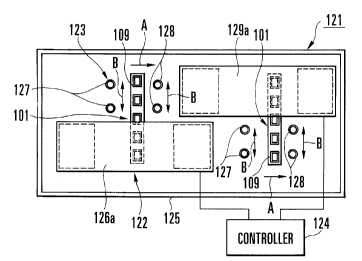
Referring to Fig. 1, reference numeral 121
denotes a flash removing apparatus. The flash removing
apparatus 121 is constituted by a convey unit 122, an
injection unit 123, and a controller 124. The convey
unit 122 horizontally conveys a lead frame 101 molded
integrally with a case 109 in the direction of an arrow
A. The injection unit 123 sprays abrasive agent-mixed
water obtained by mixing an abrasive agent in water to
- 10 -
2199112
the lead frame 101 during conveyance. The controller
124 controls the convey unit 122. The flash removing
apparatus 121 also has a recovery tank 125 at its lower
portion to recover the abrasive agent-mixed water and
the removed flash.
As shown in Fig. 2, the convey unit 122
conveys the molded lead frames 101 by sandwiching their
major surfaces between its sets of upper and lower pairs
of belt conveyors 126a and 126b, and 129a and 129b
having different rotating directions. As shown in
Fig. 1, the upstream belt conveyors 126a and 126b convey
each lead frame 1 by sandwiching its half in the
longitudinal direction such that its remaining half
projects aside from the belt conveyors 126a and 126b.
As shown in Fig. 2, the downstream belt
conveyors 129a and 129b are disposed on the projecting
side of the lead frame 101 conveyed by the upstream belt
conveyors 126a and 126b such that upstream end portions
(rollers) of belt conveyors 129a and 129b substantially
overlap the downstream end portions (rollers) of the
upstream belt conveyors 126a and 126b when seen from the
side. More specifically, the belt conveyors 126a and
126b, and 129a and 129b are arranged to convey the lead
frames 101 by alternately sandwiching their halves.
With this arrangement, the lead frame 101
which has been conveyed to the downstream end portions
of the upstream belt conveyors 126a and 126b can be
- 11 -
21991 12
directly transferred to the downstream belt conveyors
129a and 129b. When the downstream belt conveyors 129a
and 129b convey the lead frame 101, its portion
sandwiched by the upstream belt conveyors 126a and 126b
projects aside from the downstream belt conveyors 129a
and 129b.
The injection unit 123 has a plurality of
upper nozzles 127 and lower nozzles 128 for spraying the
abrasive agent-mixed water, obtained by mixing an
abrasive agent in water, at a predetermined flow rate.
The spray direction of the upper nozzles 127 is directed
downward, while the spray direction of the lower nozzles
128 is directed upward. In Fig. 2, the abrasive
agent-mixed water sprayed from the upper and lower
nozzles 127 and 128 is denoted by reference symbols W.
Two pairs of upper and lower nozzles 127 and
128 are disposed beside the upstream and downstream belt
conveyors 126a and 126b, and 129a and 129b,
respectively. The upstream and downstream nozzles 127
and 128 are arranged on the same convey line of the lead
frames 101. The upper nozzles 127 are arranged upstream
the lower nozzles 128 in the convey direction of the
lead frames 101. The nozzles 127 and 128 spray the
abrasive agent-mixed water W to the projecting portions
of the lead frames 101 during conveyance from above and
below, respectively.
- 12 -
2199112
The nozzles 127 and 128 are coupled to a drive
unit (not shown) and are reciprocally driven in the
directions of arrows B (the widthwise direction of the
belt conveyors 126a and 126b, and 129a and 129b)
perpendicular to the convey direction of the lead frames
101. When driving the nozzles 127 and 128, they are not
limited to be reciprocally moved merely linearly, but
can be reciprocally moved to draw an arc.
In addition, the flow rate of the abrasive
agent-mixed water W sprayed from the nozzles 127 and 128
is set to the minimum value with which the abrasive
agent will not stay midway along the pipe that guides
the abrasive agent-mixed water W to the nozzles 127 and
128. Therefore, when the abrasive agent-mixed water W
is sprayed to the case 109 of the lead frame 101, the
surface of the case 109 can be prevented from being
ground.
The controller 124 controls the convey speed
of the lead frames 101 conveyed by the convey unit 122
and sets it to a desired convey speed. More
specifically, even if the flow rate of abrasive
agent-mixed water W sprayed from the nozzles 127 and 128
is constant, the spray amount of abrasive agent-mixed
water W is decreased relatively by increasing the convey
speed of the lead frames 101.
The lead frame flash removing operation of the
flash removing apparatus having the above arrangement
- 13 -
2199112
will be described. First, the lead frame 101 and the
case 109 are integrally molded by insertion molding or
the like in accordance with the same scheme as that
shown in Figs. 4 to 6, and the lead frame 101 extracted
from the molding die is supplied to the flash removing
apparatus 121. At this time, flashes are formed on the
surfaces of the molded lead frame 101.
The lead frame 101 supplied to the flash
removing apparatus 121 is inserted between the upstream
belt conveyors 126a and 126b such that its half in the
longitudinal direction projects aside. At this time,
the convey speed of the lead frame 101 conveyed by the
upstream and downstream belt conveyors 126a and 126b,
and 129a and 129b is controlled by the controller 124 to
be relatively faster than in the second conveyance (to
be described later). Before inserting the lead frame
101 between the upstream belt conveyors 126a and 126b,
the nozzles 127 and 128 of the injection unit 123 are
reciprocally driven to spray the abrasive agent-mixed
water W, thus making a preparation.
When the lead frame 101 is conveyed as it is
sandwiched by the upstream belt conveyors 126a and 126b,
the abrasive agent-mixed water W supplied from the upper
nozzles 127 is sprayed to the projecting portion of the
lead frame 101 from above, and subsequently the abrasive
agent-mixed water W from the lower nozzles 128 is
sprayed to this portion from below. Fig. 3A shows a
- 14 -
2199112
state wherein the abrasive agent-mixed water W supplied
from the nozzles 127 and 128 is sprayed to the lead
frame 101.
At this time, since the nozzles 127 and 128
are reciprocally driven in the widthwise direction of
the belt conveyors 126a and 126b, i.e., in the
directions of the arrows B perpendicular to the convey
direction of the lead frame 101, the abrasive
agent-mixed water W is sprayed to the entire upper and
lower surfaces of the projecting portion of the lead
frame 101 during conveyance.
When the lead frame 101 is conveyed to the
downstream end portions of the upstream belt conveyors
126a and 126b, the projecting portion of the lead frame
101 is sandwiched between the downstream belt conveyors
129a and 129b. Hence, the lead frame 101 is conveyed by
the downstream belt conveyors 129a and 129b as its half
sandwiched by the upstream belt conveyors 126a and 126b
projects.
When the downstream belt conveyors 129a and
129b start conveyance of the lead frame 101, the
abrasive agent-mixed water W supplied from the upper
nozzles 127 is sprayed to the half of the lead frame 101
which projects from the downward belt conveyors 129a and
129b, and subsequently the abrasive agent-mixed water
from the lower nozzles 128 is sprayed to it. Thus, the
abrasive agent-mixed water W is sprayed to the entire
- 15 -
2199112
upper and lower surfaces of the projecting portion of
the remaining half of the lead frame 101.
In this manner, when the lead frame 101 is
supplied to the convey unit 122 while the injection unit
123 is being driven, the abrasive agent-mixed water W is
sprayed to the entire upper and lower surfaces of the
lead frame 101.
In the first conveyance described above, as
shown in Fig. 3A, the convey speed of the lead frame 101
is controlled so that, when the abrasive agent-mixed
water W is sprayed to flashes 116 and 117, it is sprayed
in such a spray amount that causes cracking upon
collision of the abrasive agent against the flashes 116
and 117.
After the abrasive agent-mixed water W is
sprayed to the lead frame 101, the lead frame 101 is
subjected to the electrolytic process. More
specifically, as shown in Fig. 3B, the lead frame 101 is
dipped in an electrolytic solution 129 in an
electrolytic cell 110, and a DC voltage is applied
across the lead frame 101 and a plate-like carbon
electrode 130 such that the lead frame 101 becomes the
cathode.
When the lead frame 101 is subjected to the
electrolytic process, the electrolytic solution 129
permeates into it through the cracks formed in its
flashes 116 and 117 to come into contact with the lead
- 16 -
2199112
frame 101 on the lower side of the flashes 116 and 117.
Then, bubbles are generated in the entire regions of
portions of the lead frame 101 to which the flashes 116
and 117 attach. Even if the flashes 116 and 117 are
thick, they are substantially entirely separated from
the lead frame 101 or attach to it only slightly in the
electrolytic process step described above.
After the electrolytic process, the lead frame
101 is supplied to the flash removing apparatus 121
again, and the abrasive agent-mixed water W is sprayed
to the entire upper and lower surfaces of the lead frame
101. In this second convey step, the convey speed of
the lead frame 101 is controlled by the controller 124
to be lower than in the first convey step. More
specifically, the spray amount of abrasive agent-mixed
water W in the second convey step is larger than that in
the first convey step. Fig. 3C shows a state wherein
the abrasive agent-mixed water W is sprayed to the lead
frame 101 in the second convey step.
While the spray amount of abrasive agent-mixed
water W is controlled in this manner, when the lead
frame 101 is conveyed from the upstream end portions of
the upstream belt conveyors 126a and 126b to the
downstream end portions of the downstream belt conveyors
129a and 129b, flashes 116a and 117a remaining in the
electrolytic process step and shown in Fig. 3C are
entirely removed. Thereafter, the lead frame 101
- 17 -
2199112
unloaded from the downstream belt conveyors 129a and
129b is washed with running water and further washed
with a stock solution of alcohol.
When the lead frame 101 is washed with the
stock solution of alcohol, water that has attached to
the lead frame 101 in the previous step is replaced with
alcohol, and the replacing alcohol is evaporated to dry
the lead frame 101. When washing the lead frame 101
with the stock solution of alcohol, the lead frame 101
may be dipped in a tank containing a stock solution of
alcohol, or the lead frame 101 may be exposed to a
running stock solution of alcohol.
After flash removal from the lead frame 101 is
ended, a bonding step of bonding a chip 118, a wire
bonding step, a cap adhering step, and an outer lead
cutting and bending step are performed in the same
manner as in the conventional case, thereby forming an
ultra-high frequency device.
According to this embodiment, when removing
the flashes 116 and 117 formed on the surfaces of the
lead frame 101, if the scheme is employed in which the
abrasive agent-mixed water W is sprayed to the molded
lead frame 101 and thereafter the lead frame 101 is
subjected to the electrolytic process, then cracks are
formed in the flashes 116 and 117 before the
electrolytic process is performed. When the cracks are
formed, the electrolytic solution 129 permeates into the
- 18 -
2199112
cracks in the electrolytic process step to come into
contact with the lead frame 101 on the lower side of the
flashes 116 and 117, thereby generating bubbles on the
entire regions of portions where the flashes 116 and 117
are formed.
Even if the flashes 116 and 117 are thick,
they are substantially entirely separated from the lead
frame 101 or attach to it only slightly in the
electrolytic process step described above. In the step
of spraying the abrasive agent-mixed water W after the
electrolytic process step, even if the spray amount is
small, the flashes 116 and 117 can be entirely,
completely removed. In other words, the external force
which is applied to the lead frame 101 to remove the
flashes 116 and 117 can be small.
After the second convey step, when the scheme
is employed in which the lead frame 101 is washed with
the stock solution of alcohol and dried, even if water
is used to remove the flashes 116 and 117, the lead
frame 101 can be dried without using a drier.
Furthermore, the flash removing apparatus 121
has the convey unit 122, the injection unit 123, and the
controller 124. The convey unit 122 conveys the lead
frame 101 molded integrally with the case 109 in a
direction parallel to the major surface of the lead
frame 101. The injection unit 123 sprays the abrasive
agent-mixed water W to the lead frame 101 which is being
- 19 -
X199112
conveyed by the convey unit 122. The controller 124
controls the spray amount of abrasive agent-mixed water
W by changing the lead frame convey speed of the convey
unit 122. Therefore, the spray amount of abrasive
agent-mixed water W can be controlled while maintaining
the flow rate of abrasive agent-mixed water W sprayed
from the injection unit 123 to the optimum constant
value with which the abrasive agent will not stay in the
pipe.
The method has been described above wherein
after the electrolytic process is performed, the
abrasive agent-mixed water W is sprayed to the lead
frame 101 again. Since the flashes 116 and 117 can be
removed more easily in the electrolytic process step
than with the conventional scheme, the abrasive agent
need not be used in this second spray step. After the
electrolytic process step, ultrasonic cleaning may be
performed in place of spraying the abrasive agent-mixed
water W.
The flash removing apparatus 121 need not
spray the abrasive agent-mixed water W to the both upper
and lower surfaces of the lead frame 101, but can spray
the abrasive agent-mixed water W only from above. In
this latter case, after one surface of the lead frame
101 undergoes the spray process, the lead frame 101 is
reversed automatically or manually, and the other
surface of the lead frame 101 is subjected to the spray
- 20 -
2199112
process. In this case, the arrangement of the convey
unit 122 can be the same as that shown in Figs. 1 and 2.
With this arrangement, the abrasive agent-mixed water W
is not sprayed upward. Therefore, a scattering
preventive cover need not be formed above the nozzles,
thus obtaining a small flash removing apparatus.
Practical numerical data on the flash removing
apparatus 121 of the embodiment described above will be
shown. The diameter of the upper and lower nozzles 127
and 128 is 12 mm, and the pressure of the abrasive
agent-mixed water W supplied to the nozzles 127 and 128
is 2.0 kg/cmZ. To prepare the abrasive agent-mixed water
W, a urea resin powder and an iron powder are mixed to
form an abrasive agent, and this abrasive agent is mixed
in water at a concentration of 20~. As the urea resin
powder, one with a hardness of 3.5 Mohs, a specific
gravity of 1.47 to 1.52, and a pH of 6 to 7 is used.
The amount of iron powder is 0.05 at maximum in weight
ratio.
When spraying the abrasive agent-mixed water W
to the lead frame 101, the convey speed of the lead
frame 101 conveyed by the convey unit 122 is 0.9 m/min
in the first spray step and 0.7 m/min in the second
spray step. As the electrolytic solution 129 for the
electrolytic process, one obtained by mixing soda lye
and a sodium cyanide in equal amounts is used. The
electrolytic process is performed by dipping the lead
- 21 -
z~99> >z
frame 101 for 12 minutes in the electrolytic solution
129 heated to 50°C. At this time, the current density
is 2 A/dM.
As has been described above, with the lead
frame flash removing method and apparatus according to
the present invention, a flash can be removed easily
while shortening a time required for the electrolytic
process without using a high-pressure blast finisher in
a later step. Even a small, hollow package will not be
blown off with the water pressure, leading to an
improvement in yield.
Since a conventional large, expensive unit,
e.g., a high-pressure blast finisher, becomes
unnecessary, the space occupied by the flash removing
apparatus can be small, and the cost of the flash
removing step can be decreased. Also, a lead frame
drier becomes unnecessary.
- 22 -