Note: Descriptions are shown in the official language in which they were submitted.
W O 96/07439 2 ~ 9 ~ 1 7 6 PC~rnUS95/11426
DESCRIPTION
A SAFETY SYRINGE
TECHNICAL FIELD
This invention relates, generally, to syringes, and
particularly, syringes designed for shielding the needle of
the syringe so as to prevent accidental sticks.
BACKGROUND ART
In the medical field, prevention of accidental sticks
by used needles is a constant concern. Countless injections
using syringes are made every day in a variety of settings.
As with all medical procedures, prevention of infection is
a primary concern. Syringes are typically packaged with a
protective cover over the needle. The operator removes this
cover prior to administering the injection.
If the syringe has not come pre-filled, the operator
will draw up the medication, which is in fluid form, into the
syringe. The fluid is drawn into the syringe by inserting
the needle into the container of medication fluid. The
syringe plunger is pulled away from the needle end of the
syringe barrel, creating a vacuum in the syringe. The vacuum
causes the medication to be drawn into the syringe through
the needle. The operator observes the position of the
syringe plunger in relation to volume marks found on the
syringe body. When the plunger has reached the desired mark
corresponding to the correct dosage, the operator removes the
needle from the container and holds the syringe, needle end
up, so that all air in the syringe will go to the needle.
The operator then pushes in the plunger slightly, sometimes
tapping the side of the syringe, until any air in the syringe
has been purged out through the needle.
The operator sets the syringe aside and prepares the
injection site. Once the injection site is prepared, the
operator inserts the needle into the patient and pushes in
the plunger, injecting the medication into the patient. When
the plunger has been fully depressed into the syringe body,
W096/07439 PCT~S95/11426
2199176
the operator removes the needle from the patient.
The next few moments are crucial in infection control.
The used syringe, immediately after it has been removed from
the patient, is commonly known as a dirty needle.
Frequently, hospitals and physicians' offices have special
receptacles in the patient and ex~m;n'ng rooms for disposal
of dirty needles. The operator will usually replace the
cover on the needle and place the syringe into a proper
receptacle. But in the few moments, or even the few seconds,
between the removal of the syringe from the patient and the
placement of the cover over the needle an accidental dirty
needle stick can occur. Because of the dangers associated
with this procedure, OSHA has proscribed the practice of
manual replacement of needle covers. Nonetheless, this
prohibited practice continues largely out of habit and the
lack of a safe and convenient alternative.
Dirty needle sticks can occur during this time for any
number of reasons. In emergency rooms and other settings,
patient may be fighting the treatment, and may push the used
needle into the operator or other medical professionals
around the patient. Children or even some adults become
frightened by the pain of a shot and may react, involuntarily
or voluntarily, by jerking or some other motion which can
cause an accidental stick. Other factors not attributable
to the patient include fatigue of the operator, poor lighting
conditions (e.g. at night in a patient's dark room), and
simple lapses in following procedures. Some of these
conditions may cause the operator to stick themselves when
simply replacing the cover on the needle.
Numerous attempts have been made to provide a device
which will prevent or minimize dirty needle sticks. U.S.
Patent No. 4,973,316 to Dysarz discloses a syringe in which
a compressed spring assembly within the syringe barrel is
used in combination with a trigger assembly. The device in
Dysarz retracts the needle after the injection is given.
However, the device in Dysarz requires the use of numerous
moving parts and an internal spring in the syringe body. The
W096/07439 ~ 9 9 ~ 7 6 PCT~S95/11426
device in Dysarz also requires separate manipulation of the
syringe by the operator after giving the injection. Dysarz
does not disclose automatic shielding of the needle with the
administration of the injection.
What is needed is a syringe which will automatically
cover the needle upon the administering of the injection.
An ideal syringe would cover the needle without the operator
having to use a second hand and would cover the needle
simultaneously with the giving of the injection. The
automatic covering feature should not interfere with the
syringe's ability to perform all the functions of a
conventional syringe, to include the ability to draw up
medications and purge air from the medication.
DISCLOSURE OF INVENTION
OBJECTS OF THE INVENTION
It is an object of the present invention to provide a
syringe which will automatically cover the needle upon the
administering of the injection to the patient.
Another object of the present invention is to provide
a syringe which will perform the automatic covering of the
needle without the operator having to use a second hand.
Another object of the present invention is to provide
a device which is compatible with current medication
packaging, specifically, the syringe must be able to draw up
medications and purge air from the drawn up medication.
Another object of the present invention is to provide
a device which is relatively easy and inexpensive to
manufacture and which is simple in operation.
SUMMARY OF THE INVENTION
A safety syringe is disclosed. The syringe includes a
syringe barrel, a plunger, a needle, a needle sleeve, and a
pushrod. The pushrod is attached to the needle sleeve at one
end while the other end protrudes slightly into the needle
end of the syringe barrel. When the plunger is fully
Wos6/o7439 PCT~S95/11426
219ql76
inserted into the barrel to administer an injection, the
plunger moves the pushrod. The pushrod in turn moves the
sleeve to a position in which the sleeve covers the needle.
An advantage of the invention is that it automatically
covers the pointed end of the needle of the syringe as the
operator administers the injection.
A further advantage of the invention is that the cover
is automatically locked over the pointed end of the needle
of the syringe as the operator administers the injection.
A further advantage of the invention is that the
operator does not have to use a second hand to cover the
needle or lock the cover in position.
A further advantage of the invention is that the syringe
can still be used in the conventional manner for drawing up
medications.
A further advantage of the invention is that it is
relatively inexpensive and easy to manufacture and is very
simplistic in its operation.
These and other objects, features, and advantages of
this invention will be apparent from the following
descriptions of the invention.
DESCRIPTION OF DRAWINGS
Figure l is a sectional view of the invention with the
sleeve in the exposed position.
Figure 2 is a sectional view of the invention with the
sleeve in the covered position.
Figure 3 is a sectionaI view of the locking arms
extending from the barrel of the invention.
Figure 4 is a sectional view of the resilient base
extending from the sleeve of the invention.
Figure 5 is a sectionaI view of the invention with the
sleeve locked in the safe position by the locking arms and
the resilient base.
BEST MODE FOR CARRYING OUT THE INVENTION
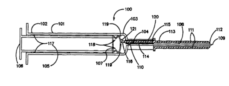
Referring to Figure l, a sectional view of safety
WOs6/07439 2 1 q 9 1 7 6 PCT~Ss5/11426
syringe 100 is shown with the sleeve in the exposed position.
Safety syringe 100 would probably be shipped and packaged
with a removable cover (not shown). The principle components
of safety syringe 100 are barrel 101, plunger 105, needle
108, sleeve 111, and connector 114. Barrel 101 is an
elongated hollow cylindrical member made of a rigid or semi-
rigid material such as molded plastic. Barrel 101 is
transparent or translucent so that the operator can see the
medication in barrel 101. Barrel 101 has plunger end 102
which is open for receipt of plunger 105 and needle end 103.
Needle end 103 is like the needle end on conventional
syringes known in the art except it has connector aperture
104. Connector aperture 104 can be of any shape so long as
its shape matches with the cross-sectional shape of connector
114 so that when connector 114 is inserted into connector
aperture 104 a fluid-tight seal is formed. In the embodiment
shown connector aperture 104 is a cylindrical shaped hole
whose long axis is parallel with the long axis of barrel 101.
Plunger 105 has thumb end 106 and washer end 107.
Plunger 105 is an elongated rigid or semi-rigid member whose
length is adapted so that the operator can fully insert
plunger 105 into barrel 101 by pushing on thumb end 106.
Plunger 105 will typically be constructed of molded plastic.
Washer end 107 is adapted so that when washer end 107 is
inserted into barrel 101 a fluid-tight seal is formed between
washer end 104 and barrel 101. Washer end may be constructed
with an optional washer or plurality of washers to form this
fluid-tight seal. Or, as depicted, washer end 104 may be
constructed with no washers, a configuration in which washer
end is sized to correspond with the inner dimensions of
barrel 101. Needle 108 is a hollow rigid elongated member
typically constructed from a strong metal such as stainless
steel. Needle 108 has pointed end 109 which will make the
puncture into the patient. Opposite pointed end 109 is
syringe end 110 of needle 108 which is rigidly connected to
needle end 103 of syringe 101. Syringe end 110 can be
affixed to barrel 101 by any conventional method known in the
W096/07439 21 991 76 PCT~S95111426
art such as gluing or making syringe end 110 with a tab which
is perpendicular to needle 108 and locked into needle end 103
of barrel 101.
Safety syringe 100 includes sleeve 111 which is an
elongated hollow semi-rigid member slidably positionable over
needle 108. Sleeve 111 has a point-covering end 112 and
connecting end 113. Sleeve 111 can be moved along needle 108
between two positions - an exposed position depicted in FIG.
1 in which sleeve 111 covers substantially all of needle 108
10except a small portion of needle 108 at pointed end 109, and
a safe position depicted in FIG. 2 in which sleeve 111 covers
substantially all of needle 108 including pointed end 109.
Insertion of connector 114 into connector aperture 104
prevents rotation of sleeve 111 about needle 108.
15Passing through connector aperture 104 is connector 114.
Connector 114 is an elongated rigid or semi-rigid member
having sleeve end 115 and barrel end 116. Barrel end 116 is
adapted to have the same cross-sectional shape as connector
aperture 104 so that barrel end 115 is slidably inserted
through connector aperture 104.
When sleeve 111 is in the exposed position barrel end
115 protrudes into barrel 101 a pre-determined distance. In
the embodiment depicted, this pre-determined distance is
approximately one-fourth of an inch. However, one skilled
in the art could practice the invention with this distance
being greater and lesser than one-fourth of an inch. Sleeve
end 115 of connector 114 is connected to sleeve 111 so that
as plunger 105 is depressed into barrel 101, washer end 107
will contact connector 114 which will cause sleeve 111 to
move to the safe position. In the embodiment depicted,
connector 114 and sleeve 111 form a unitary member, but one
skilled in the art could practice the invention with sleeve
111 and connector 114 being separate members.
Although in the embodiment depicted, sleeve 111 is made
of Teflon and connector 114 is made of molded plastic, one
could use any semi-rigid material for sleeve 111 and any
rigid or semi-rigid material for connector 114.
W096t07439 ~l 991 76 P~l/u~5/11426
Additionally, although the embodiment depicted shows only one
connector 114, one could practice the invention with two or
more connectors.
Connector 114 and connector aperture 104 are adapted
such that they form a fluid-tight seal while still allowing
connector 114 to be slidable within and through connector
aperture 104. In the embodiment deplcted this fluid tight
seal is achieved by using grommet 120 which will fit between
connector 114 and connector aperture 104. One skilled in the
art could also practice the invention without grommet 120.
Without grommet 120 the fluid-tight seal would be achieved
by appropriately sizing connector 114 and connector aperture
104.
Connector 114 includes catch 121 at barrel end 116.
Catch 121 prevents connector 114 and sleeve 111 from being
pulled out of barrel 101 when safety syringe is removed from
the patient. In the embodiment depicted catch 121 is a small
tab integral to connector 114 but one skilled in the art
could practice the invention with catch 121 being a lip
around completely surrounding connector 114 or using any
conventional means to prevent connector 114 from passing
completely out of connector aperture 104.
In order to allow medication to be drawn into safety
syringe 101 while still preserving the automatic needle-
covering feature of safety syringe 100, one or more stop
means 118 are fixably attached to interior wall 117 of barrel
101. Stop means 118 are positioned intermediate needle end
103 and plunger end 102 of barrel 101. Stop means 118 are
adapted so that stop means 118 engage washer end 107 so as
to prevent plunger 105 from traveling past stop means 118 and
moving connector 114. Stop means are also adapted such that
if the operator applies sufficient force washer 107 can
travel beyond stop means 118 and move connector 114 which in
turn moves sleeve 111 from the exposed position to the safe
position.
In the embodiment depicted stop means 118 are one or
more nibs 119. Nibs 119 are deformable plastic members which
W096/07439 PCT~S95/11426
2199176
protrude from interior wall 117 a sufficient distance so as
to engage washer end 107. Upon the application of sufficient
force by the operator on thumb end 106 of plunger 105, nibs
119 deform and bend, thereby allowing washer end 107 to
travel all the way to needle end 103 of barrel 101, causing
sleeve 101 to move to the safe position.
Although in the embodiment depicted, stop means 118 are
nibs 119, one skilled in the art could make stop means 118
by making barrel 101 of smaller diameter at needle end 103
and making washer end 107 with deformable members two
diameters. Stop means 118 could also be a sliding tab,
perpendicular to the long axis of barrel 101, the tab being
adapted such that the operator could push it into or pull it
out of the barrel, or any other conventional means of
selectively stopping the travel of a syringe plunger in a
syringe barrel.
Stop means 118 is positioned a sufficient distance away
from needle end 103 of barrel 101 so as to allow connector
114 to protrude into barrel 101 without being moved by washer
end 107. Because of this spacing, there will be some air
already in safety syringe 100 when fluid is drawn into safety
syringe 100. The operator must then purge the air from
safety syringe 100 using the conventional method of holding
safety syringe vertically with needle 108 pointing upward and
depressing plunger 105 into barrel 101 until the air is
expelled from needle 108. Stop means 119 cannot be
positioned so far back from needle end 103 of barrel 101 that
an inordinate amount of air will be disposed in safety
syringe 100 after drawing medication. The air must be able
to be expelled by moving plunger 105 toward said plunger end
102 of barrel 101 without moving washer end 107 beyond stop
means 118.
In most conventional syringes known in the art, there
are marks on the syringe barrel to indicate volume
measurements of fluid in the syringe. Safety syringe 100
will have volume marks 201 along barrel 101 which will
indicate the amount of fluid which has been drawn into barrel
wog6/07439 21 991 76 PCT~S95/11426
101. Volume marks 201 will include zero mark 203 and at
least one unit mark 202. The zero mark will be aligned with
stop means 118. In the embodiment depicted one could
eliminate zero mark 203 and use nibs 119 as zero mark 203.
Zero mark 203 and unit marks 202 can be make by lines painted
or etched on barrel 101.
In order to allow the sleeve 111 to be locked in the
safe position, a pair of locking arms is attached to the
needle end of the barrel 103. The first arm 300 has a barrel
end 301 and a needle end 302. The first arm 300 also has a
an inner surface 303 and an outer surface 304. The
longitudinal axis of the first arm 300 is substantially
parallel to the longitudinal axis of the barrel 101. The
second arm 400 has a barrel end 401 and a needle end 402. The
second arm 400 also has an inner surface 403 and an outer
surface 404. The second arm 400 is longer than the first arm
300. Arms 300 and 400 will typically be composed of molded
plastic and be integrally attached to the barrel 101.
A first detent 305 is attached to the needle end 302 of
the first arm 300. The first detent 305 extends inward from
the needle end 302 of the first arm 300 towards needle 108,
and the longitudinal axis of the first detent 300 is
substantially perpendicular to the longitudinal axis of the
barrel 101. The first detent 305 has a barrel surface 306 and
a needle surface 307. The first detent 305 also has an arm
end 308 and a free end 309. The free end 309 of the first
detent 305 is beveled so that the barrel surface 306 of the
first detent 305 is shorter than the needle surface 307 of
the first detent 305. A second detent 405 is attached to the
needle end 402 of the second arm 400. The second detent 405
extends inward from the needle end 402 of the second arm 400
towards the needle 108, and the longltudinal axis of the
second detent 405 is substantially perpendicular to the
longitudinal axis of the barrel 101. The second detent 405
has a barrel surface 406 and a needle surface 407. The
second detent 405 also has an arm end 408 and a free end 409.
Detents 305 and 405 will typically be composed of molded
W096/07439 2199l?6 PCT~S9S/11426
plastic and be integrally attached to the arms 300 and 400,
one to each arm. The free end 409 of the second detent 405
and the free end 309 of the first detent 305 define a detent
gap 350. The distance from the needle end of the barrel 103
to the first detent 305 must be greater than or equal to the
distance the sleeve 111 must move to reach the safe position.
The difference between the distance from the second detent
405 to the needle end of the barrel 103 and the distance from
the first detent 305 to the needle end of the barrel 103 must
be at least the thickness of the lip unit 133 but may not
be so great as to allow the sleeve 111 to slip off the
pointed end 109 of the needle 108.
A resilient base 130 is integrally attached to the
connecting end 113 of the sleeve 111. The base 130 is
conical in the embodiment shown; however, other geometrical
designs may be substituted. The base 130 has a connecting
end 131 and a sleeve end 132. A lip unit 133, integral with
the base 130, extends from the connecting end 113 of the base
130. By virtue of the fact that the base 130 is a cone, the
lip unit 133 forms a ring, lip ring 134. Other obvious
shapes for the lip unit 133 may be substituted for the ring
shape. The lip unit 133 has a base edge 135 a free edge 136.
The diameter of the lip ring 134 measured from the free edge
136 is greater than the width of the detent gap 350 but less
than or equal to the distance between the inner surface 303
of the first arm 300 and the inner surface 404 of the second
arm 400. Of course, if another geometrical configuration is
used, the distance separating the elements comprising the lip
unit 133 must conform to the requirements given here
regarding diameter.
By applying an inward force to the resilient base 130,
the width of the lip unit 133 may be reduced so that the lip
unit 133 may be passed through the detent gap 350 as the
sleeve 111 is slidably positioned over the needle 108. At
this point, the lip unit 133 is positioned between the needle
end of the barrel 103 and the first detent 305.
As the connector 114 moves the sleeve 111 forward, it
W096/07439 2 1 9 9 1 7 6 PCT~S95,ll426
will move the base 130 and the lip unit 133 forward as well.
After the sleeve 111 has been moved into the safe position,
the lip unit 133 will engage the barrel surface 306 of the
first detent 305. Because the free end 309 of the first
detent 305 is beveled, it will allow the lip unit 133 to
pass. After the lip unit 133 has passed the first detent
305, the needle surface 307 of the first detent 305 will not
allow the lip unit 133 to retreat. The barrel surface 406
of the second detent 405 will not allow the lip unit 133 to
advance past it. The lip unit 133 is, thereby, locked
between the first detent 305 and the second detent 405.
Because the lip unit 133 is integrally attached to the base
130 which in turn is integrally attached to sleeve 111, the
sleeve 111 is locked in the safe position.
Although in the embodiment depicted, there are two arms,
one could practice the invention using a single arm that
contained both indents. More than two arms could be utilized
to provide greater locking strength. Also, a ring containing
both indents could be used. Other obvious variations on the
embodiment shown include substituting the resilient conical
base with resilient wings that each have a lip at the end,
or replacing the resilient conical base with any other
geometric configuration.
Safety syringe 100 is shipped in sterile packaging and
normally will have a removable cover (not shown) over needle
108 and sleeve 111. In operation, the operator removes the
removable cover and inserts needle 108 into a container of
medication fluid. The operator pulls plunger 105 in a
direction away from needle 108 so that the fluid is drawn
into barrel 101 until washer end 107 is in alignment with the
appropriate unit marks 202. The operator withdraws needle
108 from the container. The operator pushes the needle into
the injection site on the patient. Once the needle is
appropriately positioned in the patient, the operator pushes
on thumb end 106 of plunger 105, applying enough force to
move washer end 107 of plunger 105 past stop means 118 to
needle end 103 of barrel 101. This movement causes sleeve
W O 96/07439 PC~rrUS95/11426
2199176
111 to move from the exposed position to the safe position
while pointed end 109 of needle 108 is still in the patient.
The operator removes safety syringe 100 from the patient and
disposes of safety syringe 100. The operation for covering
pointed end 109 of needle 108 is thus automatic with the
administration of the injection and is a one-handed
operation.
There are of course other alternate embodiments which
are obvious from the foregoing descriptions of the invention
which are intended to be included within the scope of the
invention as defined by the following claims: