Language selection

Search

Patent 2199278 Summary

Third-party information liability

Some of the information on this Web page has been provided by external sources. The Government of Canada is not responsible for the accuracy, reliability or currency of the information supplied by external sources. Users wishing to rely upon this information should consult directly with the source of the information. Content provided by external sources is not subject to official languages, privacy and accessibility requirements.

Claims and Abstract availability

Any discrepancies in the text and image of the Claims and Abstract are due to differing posting times. Text of the Claims and Abstract are posted:

  • At the time the application is open to public inspection;
  • At the time of issue of the patent (grant).
(12) Patent Application: (11) CA 2199278
(54) English Title: CIRCULAR WING AIRCRAFT
(54) French Title: AERONEF A AILES CIRCULAIRES
Status: Deemed Abandoned and Beyond the Period of Reinstatement - Pending Response to Notice of Disregarded Communication
Bibliographic Data
(51) International Patent Classification (IPC):
  • B64C 27/22 (2006.01)
  • B64C 39/06 (2006.01)
(72) Inventors :
  • VASS, GABOR I. (Canada)
(73) Owners :
  • GABOR I. VASS
(71) Applicants :
  • GABOR I. VASS (Canada)
(74) Agent: OSLER, HOSKIN & HARCOURT LLP
(74) Associate agent:
(45) Issued:
(86) PCT Filing Date: 1995-09-05
(87) Open to Public Inspection: 1996-03-14
Examination requested: 1998-09-02
Availability of licence: N/A
Dedicated to the Public: N/A
(25) Language of filing: English

Patent Cooperation Treaty (PCT): Yes
(86) PCT Filing Number: PCT/US1995/011203
(87) International Publication Number: WO 1996007586
(85) National Entry: 1997-03-05

(30) Application Priority Data:
Application No. Country/Territory Date
08/300,757 (United States of America) 1994-09-06

Abstracts

English Abstract


A circular wing aircraft (10) in the form of a helicopter (12) comprising a
fuselage (14) and a circular wing assembly (16). A structure (18) is for
mounting the circular wing assembly (16) above the fuselage (14) in a
stationary manner. An air impeller unit (20) is rotatively carried within the
circular wing assembly (16). A device (22) is for driving the air impeller
unit (20) to rotate about a central axis (24) within the circular wing
assembly (16), so as to provide lift and flight movement while yaw control is
maintained.


French Abstract

L'invention se rapporte à un aéronef à ailes circulaires (10) se présentant sous forme d'un hélicoptère (12) comprenant un fuselage (14) et un ensemble aile circulaire (16). Une structure (18) permet la fixation de l'ensemble aile circulaire (16) au-dessus du fuselage (14). Une roue à aubes pneumatique (20) est montée rotative à l'intérieur de l'ensemble aile circulaire (16). Un dispositif (22) est destiné à entraîner la roue à aubes pneumatique (20) pour qu'elle tourne autour d'un axe central (24) à l'intérieur de l'ensemble aile circulaire (16), de manière à assurer la sustentation et le déplacement en vol tout en maintenant le contrôle en lacet.

Claims

Note: Claims are shown in the official language in which they were submitted.

-6-
CLAIMS
1. A circular wing aircraft in the form of a
helicopter comprising:
a) a fuselage;
b) a circular wing assembly, said circular wing
assembly including a lower disc wing, an upper ring
wing, and a plurality of wing mounts radially spaced
apart about the central axis and affixed between a top
surface of said lower disc wing and a bottom surface of
said upper ring wing, said upper ring wing is
airfoil-shaped in cross section and is sized to overlap
the perimeter of said lower disc wing;
c) means for mounting said circular wing
assembly above said fuselage;
d) an air impeller unit rotatively carried
within said circular wing assembly; and
e) means for driving said air impeller unit to
rotate about a central axis within said circular wing
assembly, so as to provide lift and flight movement
while way control is maintained.
2. A circular wing aircraft as recited in Claim
1, wherein said upper ring wing includes a plurality of
sectional flaps that are independently controllable
about the outer circumference for better lift and
maneuverability.
3. A circular wing aircraft as recited in Claim
2, wherein each said wing mount is airfoil-shaped in

-7-
cross section and includes a movable flap at its outer
edge, to increase and decrease a twisting force for yaw
control.
4. A circular wing aircraft as recited in Claim
3, wherein said mounting means includes a plurality of
suspension members radially spaced apart about the
central axis, with each said suspension member extending
between a top surface of said fuselage and a bottom
surface of said lower disc wing.
5. A circular wing aircraft as recited in Claim
4, wherein each said suspension member is independently
length adjustable, allowing said circular wing assembly
to be tilted in any direction relative to said fuselage,
thus allowing said fuselage to stay level in horizontal
flight and includes a first rubber shock absorber
connector at the top surface of said fuselage and a
second rubber shock absorber connector at the bottom
surface of said lower disc wing, so that vibration can
be reduced, resulting in a low noise level in said
fuselage.
6. A circular wing aircraft as recited in Claim
5, wherein said air impeller unit includes:
a) a hub;
b) a plurality of curved blades extending radially
from said hub; and
c) a drive shaft extending from said hub through
the central axis to said driving means, so that said
curved blades can rotate with said hub on said drive

-8-
shaft, to draw air from the top and blow the air out at
a high velocity in radial directions over the top
surface of said lower disc wing, to create a low
pressure zone on the top surface with static air
pressure beneath said lower disc wing, providing a
lifting force perpendicular to the bottom surface of
said lower disc wing, while the air is also blown above
a top surface and below the bottom surface of said upper
ring wing, respectively creating an additional lift.
7. A circular wing aircraft as recited in Claim
6, wherein said driving means is an engine directly
connected to said circular wing assembly and coupled to
said drive shaft.
8. A circular wing aircraft as recited in Claim
7, wherein said upper ring wing is hollow having an
annular chamber therein to be used as a fuel tank,
thereby allowing maximum space within said fuselage for
a payload.

Description

Note: Descriptions are shown in the official language in which they were submitted.


Wos6/07S86 ~ PCT~S95/11203
~ ~ 2199278
Descr;pt;on
CIRCULAR WING AIRCRAFT
Techn;cal Fiel~
The instant invention relateæ generally to aircraft
and more specifically it relates to a. circular wing
aircraft.
Descrip~;on of the Pr;or ~
Numerous aircraft have been provided in prior art.
For P~rle, U.S. patents numbered 3,486,715 to Reams;
lO 4,598,888 to Beteille; 5,101,615 to Fassauer; 5,163,638
to Chaneac; 5,244,167 to Turk et al. and 5,255,871 to
Ikeda all are illustrative of such prior art. While
these units may be suitable for the particular purpose
to which they address, they would not. be as suitable for
the purposes of the present invention as heretofore
described.
Pisclos~re of Invention
A primary object of the present invention is to
provide a circular wing aircraft that will overcome the
shortcomings of the prior art devices.
Another object is to provide a circular wing
aircraft that utilizes fewer components than currently
proAnre~ aircraft, thereby less maintenAnce requirements
are neeA~.

W O 96/07586 , PC~rrUS9S111203
. 219927~
z
An additional object is to provide a circular wing
aircraft, in which in an autogiro form a smaller
wingspan is required for s;~;lAr aircraft weight and in
a helicopter form the tail and tail rotor are
el;m;nAted, since the circular wing assembly maintains
yaw control.
A further object is to provide a circular wing
aircraft that is simple and easy to use.
A still further object is to provide a circular
1~ wing aircraft that is econnm;c~l in cost to manufacture.
Further objects of the invention will appear as the
description proceeds.
Brief Description of the Drawing Figures
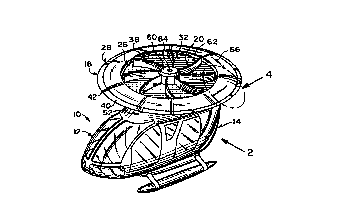
FIGURE l is a perspective view of the instant
invention incorporated into a helicopter.
FIGURE 2 is a side elevational view taken in the
direction of arrow 2 in Figure l.
FIGURE 3 is a top view of the circular wing
assembly per se taken in the direction of arrow 3 in
Figure 2.
FIGURE 4 is an enlarged perspective view of a
portion of the circular winy assembly as ; n~ ted by
arrow 4 in Figure l.
FIGURE 5 is a cross sectional view taken along line
5-5 in Figure 3.
FIGURE 6 is a cross sectional perspective view of a
modified circular wing assembly.

- ' ` ~
W096/07586 pcT~ss5lll2o3
1 99278
FIGURE 7 is a perspective view of the instant
invention incorporated into an autogiro.
Det~iled Descript;on of the P~eferred ~hodim~nts
Turning now descriptively to the drawings, in which
similar reference characters denote s;~il~r elements
throughout the several views, Figures 1 and 2 illustrate
a circular wing aircraft 10 in the form of a helicopter
12, comprising a fuselage 14 and a circular wing
assembly 16. A structure 18 is for mounting the
circular wing assembly 16 above the fuselage 14 in a
stationary manner. An air impeller unit 20 is
rotatively carried within the circular wing assembly 16.
A device 22 is for driving the air impeller unit 20 to
rotate about a central axis 24 within the circular wing
assembly 16, so as to provide lift and flight movement
while yaw control is maintAi ne~ .
The circular wing assembly 16, as best seen in
Figures 3 through 6, consists of a lower disc wing 26
and an upper ring wing 28. A plurality of wing mounts
30, are rA~ ly spaced apart about the central axis 24
and affixed between a top surface 32 of the lower disc
wing 26 and a bottom surface 34 of the upper ring wing
Z8.
The upper ring wing 28 is airfoil-shaped 36 in a
cross section and is sized to overlap the perimeter 38
of the lower disc wing 26. The upper ring wing 28
contains a plurality of sect; Q~l flaps 40 that are

W096/07s86 . PCT~Sg5/11203
1 99278
_4_
independently controllable about the outer circumference
42, for better lift and maneuverability. Each wing
mount 30 is airfoil- shaped 44 in cross section and
includes a movable flap 46 at its outer edge 48, to
increase and decrease a twisting force for yaw control.
The mounting structure 18 includes a plurality of
suspension members 50 rA~;~lly spaced apart about the
central axis 24. Each suspension membn member 50 extends
between a top surface 52 of the fuselage 14 and a bottom
IQ surface 54 of the lower disc wing 26. Each suspension
member 50 is independently length adjustable. The
circular wing assembly 16 can be tilted in any direction
relative to the fuselage 14, thus allowing the fuselage
14 to stay level in horizontal flight. A first rubber
shock absorber connector 56 is at the top surface 52 of
the fuselage 14. A second rubber shock absorber
connector 58 is at the bottom surface 54 of the lower
disc wing 26, so that vibration can be reduced,
resulting in a low noise level in the fuselage 14.
The air impeller unit 20 contains a hub 60, with a
plurality of curved blades 62 ext~n~;ng rA~;Ally from
the hub 60. A drive shaft 64 extends from the hub 60
through the central axis 24 to the driving device 22.
The curved blades 62 can rotate with the hub 60 on the
25 drive shaft 64, to draw air from the top and blow the !.
air out at a high velocity in radial directions over the
top surface 32 of the lower disc wing 26. This creates
a low pressure zone on the top surface 32 with static

W096/07586 ~ PCT~Sg5/11203
` .` 2 ~ 9~278
air pressure beneath the lower disc wing 26, providing a
lifting force perpendicular to the botlom surface 54 of
the lower disc wing 26. The air is also blown above a
top surface 66 and below the bottom suxface 34 of the
upper ring wing 28, respectively creat:Lng an additional
lift.
The driving device 22 is an engine 68 directly
connected to the circular wing assembly 16 and coupled
to the drive shaft 64. The upper ring wing 28 can be
lo hollow, as shown in Figures 4 and 5, having an annular
chamber 70 therein to be used as a fuel tank, thereby
allowing maximum space within the fuselage 14 for a
payload.
Figure 7 shows a circular wing air.craft lOa in the
form of an autogiro 72, comprising a fuselage 74. A
pair of short fixed wings 76, each extend outwardly from
an opposite side at the middle of the i.uselage 74. A
pair of 5~hi 1; ~ers 78, each extend out;wardly from an
opposite side at the tail 80 of the fuæelage 74. A
rudder 82 extends upwardly from the tail 80 of the
fuselage 74. A pair of circular wing assemblies 16, are
each pivotally mounted and controlled on a distal free
end 84 of one short fixed wing 76. A pair of air
=~ .. . . . . = . . ,
impeller units 20, are each rotatively driven within one
circular wing assembly 16, to rotate about a central
axis 24 by an engine (not shown), so as to provide lift
and flight movement while yaw control is maint~ine~.

Representative Drawing
A single figure which represents the drawing illustrating the invention.
Administrative Status

2024-08-01:As part of the Next Generation Patents (NGP) transition, the Canadian Patents Database (CPD) now contains a more detailed Event History, which replicates the Event Log of our new back-office solution.

Please note that "Inactive:" events refers to events no longer in use in our new back-office solution.

For a clearer understanding of the status of the application/patent presented on this page, the site Disclaimer , as well as the definitions for Patent , Event History , Maintenance Fee  and Payment History  should be consulted.

Event History

Description Date
Inactive: Agents merged 2013-10-24
Application Not Reinstated by Deadline 2001-09-05
Time Limit for Reversal Expired 2001-09-05
Deemed Abandoned - Failure to Respond to Maintenance Fee Notice 2000-09-05
Inactive: RFE acknowledged - Prior art enquiry 1998-12-07
Request for Examination Received 1998-09-02
All Requirements for Examination Determined Compliant 1998-09-02
Request for Examination Requirements Determined Compliant 1998-09-02
Inactive: Notice - National entry - No RFE 1997-08-25
Inactive: IPC assigned 1997-08-07
Inactive: First IPC assigned 1997-08-07
Inactive: IPC assigned 1997-08-07
Inactive: Filing certificate correction 1997-06-12
Filing Requirements Determined Compliant 1997-06-12
Application Published (Open to Public Inspection) 1996-03-14

Abandonment History

Abandonment Date Reason Reinstatement Date
2000-09-05

Maintenance Fee

The last payment was received on 1999-09-03

Note : If the full payment has not been received on or before the date indicated, a further fee may be required which may be one of the following

  • the reinstatement fee;
  • the late payment fee; or
  • additional fee to reverse deemed expiry.

Please refer to the CIPO Patent Fees web page to see all current fee amounts.

Fee History

Fee Type Anniversary Year Due Date Paid Date
Basic national fee - small 1997-03-05
MF (application, 2nd anniv.) - small 02 1997-09-05 1997-09-03
MF (application, 3rd anniv.) - small 03 1998-09-08 1998-09-02
Request for examination - small 1998-09-02
MF (application, 4th anniv.) - small 04 1999-09-07 1999-09-03
Owners on Record

Note: Records showing the ownership history in alphabetical order.

Current Owners on Record
GABOR I. VASS
Past Owners on Record
None
Past Owners that do not appear in the "Owners on Record" listing will appear in other documentation within the application.
Documents

To view selected files, please enter reCAPTCHA code :


To view images, click a link in the Document Description column. To download the documents, select one or more checkboxes in the first column and then click the "Download Selected in PDF format (Zip Archive)" or the "Download Selected as Single PDF" button.

List of published and non-published patent-specific documents on the CPD .

If you have any difficulty accessing content, you can call the Client Service Centre at 1-866-997-1936 or send them an e-mail at CIPO Client Service Centre.


Document
Description 
Date
(yyyy-mm-dd) 
Number of pages   Size of Image (KB) 
Cover Page 1997-08-21 1 47
Description 1997-03-05 5 170
Abstract 1997-03-05 1 63
Claims 1997-03-05 3 91
Drawings 1997-03-05 3 150
Representative drawing 1997-08-21 1 14
Notice of National Entry 1997-08-25 1 193
Acknowledgement of Request for Examination 1998-12-07 1 172
Courtesy - Abandonment Letter (Maintenance Fee) 2000-10-03 1 184
Fees 1999-09-03 1 58
PCT 1997-03-05 6 249
Correspondence 1997-06-12 1 36
Fees 1997-09-03 1 55
Fees 1998-09-02 1 65