Sélection de la langue

Search

Sommaire du brevet 2199278 

Énoncé de désistement de responsabilité concernant l'information provenant de tiers

Une partie des informations de ce site Web a été fournie par des sources externes. Le gouvernement du Canada n'assume aucune responsabilité concernant la précision, l'actualité ou la fiabilité des informations fournies par les sources externes. Les utilisateurs qui désirent employer cette information devraient consulter directement la source des informations. Le contenu fourni par les sources externes n'est pas assujetti aux exigences sur les langues officielles, la protection des renseignements personnels et l'accessibilité.

Disponibilité de l'Abrégé et des Revendications

L'apparition de différences dans le texte et l'image des Revendications et de l'Abrégé dépend du moment auquel le document est publié. Les textes des Revendications et de l'Abrégé sont affichés :

  • lorsque la demande peut être examinée par le public;
  • lorsque le brevet est émis (délivrance).
(12) Demande de brevet: (11) CA 2199278
(54) Titre français: AERONEF A AILES CIRCULAIRES
(54) Titre anglais: CIRCULAR WING AIRCRAFT
Statut: Réputée abandonnée et au-delà du délai pour le rétablissement - en attente de la réponse à l’avis de communication rejetée
Données bibliographiques
(51) Classification internationale des brevets (CIB):
  • B64C 27/22 (2006.01)
  • B64C 39/06 (2006.01)
(72) Inventeurs :
  • VASS, GABOR I. (Canada)
(73) Titulaires :
  • GABOR I. VASS
(71) Demandeurs :
  • GABOR I. VASS (Canada)
(74) Agent: OSLER, HOSKIN & HARCOURT LLP
(74) Co-agent:
(45) Délivré:
(86) Date de dépôt PCT: 1995-09-05
(87) Mise à la disponibilité du public: 1996-03-14
Requête d'examen: 1998-09-02
Licence disponible: S.O.
Cédé au domaine public: S.O.
(25) Langue des documents déposés: Anglais

Traité de coopération en matière de brevets (PCT): Oui
(86) Numéro de la demande PCT: PCT/US1995/011203
(87) Numéro de publication internationale PCT: WO 1996007586
(85) Entrée nationale: 1997-03-05

(30) Données de priorité de la demande:
Numéro de la demande Pays / territoire Date
08/300,757 (Etats-Unis d'Amérique) 1994-09-06

Abrégés

Abrégé français

L'invention se rapporte à un aéronef à ailes circulaires (10) se présentant sous forme d'un hélicoptère (12) comprenant un fuselage (14) et un ensemble aile circulaire (16). Une structure (18) permet la fixation de l'ensemble aile circulaire (16) au-dessus du fuselage (14). Une roue à aubes pneumatique (20) est montée rotative à l'intérieur de l'ensemble aile circulaire (16). Un dispositif (22) est destiné à entraîner la roue à aubes pneumatique (20) pour qu'elle tourne autour d'un axe central (24) à l'intérieur de l'ensemble aile circulaire (16), de manière à assurer la sustentation et le déplacement en vol tout en maintenant le contrôle en lacet.


Abrégé anglais


A circular wing aircraft (10) in the form of a helicopter (12) comprising a
fuselage (14) and a circular wing assembly (16). A structure (18) is for
mounting the circular wing assembly (16) above the fuselage (14) in a
stationary manner. An air impeller unit (20) is rotatively carried within the
circular wing assembly (16). A device (22) is for driving the air impeller
unit (20) to rotate about a central axis (24) within the circular wing
assembly (16), so as to provide lift and flight movement while yaw control is
maintained.

Revendications

Note : Les revendications sont présentées dans la langue officielle dans laquelle elles ont été soumises.


-6-
CLAIMS
1. A circular wing aircraft in the form of a
helicopter comprising:
a) a fuselage;
b) a circular wing assembly, said circular wing
assembly including a lower disc wing, an upper ring
wing, and a plurality of wing mounts radially spaced
apart about the central axis and affixed between a top
surface of said lower disc wing and a bottom surface of
said upper ring wing, said upper ring wing is
airfoil-shaped in cross section and is sized to overlap
the perimeter of said lower disc wing;
c) means for mounting said circular wing
assembly above said fuselage;
d) an air impeller unit rotatively carried
within said circular wing assembly; and
e) means for driving said air impeller unit to
rotate about a central axis within said circular wing
assembly, so as to provide lift and flight movement
while way control is maintained.
2. A circular wing aircraft as recited in Claim
1, wherein said upper ring wing includes a plurality of
sectional flaps that are independently controllable
about the outer circumference for better lift and
maneuverability.
3. A circular wing aircraft as recited in Claim
2, wherein each said wing mount is airfoil-shaped in

-7-
cross section and includes a movable flap at its outer
edge, to increase and decrease a twisting force for yaw
control.
4. A circular wing aircraft as recited in Claim
3, wherein said mounting means includes a plurality of
suspension members radially spaced apart about the
central axis, with each said suspension member extending
between a top surface of said fuselage and a bottom
surface of said lower disc wing.
5. A circular wing aircraft as recited in Claim
4, wherein each said suspension member is independently
length adjustable, allowing said circular wing assembly
to be tilted in any direction relative to said fuselage,
thus allowing said fuselage to stay level in horizontal
flight and includes a first rubber shock absorber
connector at the top surface of said fuselage and a
second rubber shock absorber connector at the bottom
surface of said lower disc wing, so that vibration can
be reduced, resulting in a low noise level in said
fuselage.
6. A circular wing aircraft as recited in Claim
5, wherein said air impeller unit includes:
a) a hub;
b) a plurality of curved blades extending radially
from said hub; and
c) a drive shaft extending from said hub through
the central axis to said driving means, so that said
curved blades can rotate with said hub on said drive

-8-
shaft, to draw air from the top and blow the air out at
a high velocity in radial directions over the top
surface of said lower disc wing, to create a low
pressure zone on the top surface with static air
pressure beneath said lower disc wing, providing a
lifting force perpendicular to the bottom surface of
said lower disc wing, while the air is also blown above
a top surface and below the bottom surface of said upper
ring wing, respectively creating an additional lift.
7. A circular wing aircraft as recited in Claim
6, wherein said driving means is an engine directly
connected to said circular wing assembly and coupled to
said drive shaft.
8. A circular wing aircraft as recited in Claim
7, wherein said upper ring wing is hollow having an
annular chamber therein to be used as a fuel tank,
thereby allowing maximum space within said fuselage for
a payload.

Description

Note : Les descriptions sont présentées dans la langue officielle dans laquelle elles ont été soumises.

Wos6/07S86 ~ PCT~S95/11203
~ ~ 2199278
Descr;pt;on
CIRCULAR WING AIRCRAFT
Techn;cal Fiel~
The instant invention relateæ generally to aircraft
and more specifically it relates to a. circular wing
aircraft.
Descrip~;on of the Pr;or ~
Numerous aircraft have been provided in prior art.
For P~rle, U.S. patents numbered 3,486,715 to Reams;
lO 4,598,888 to Beteille; 5,101,615 to Fassauer; 5,163,638
to Chaneac; 5,244,167 to Turk et al. and 5,255,871 to
Ikeda all are illustrative of such prior art. While
these units may be suitable for the particular purpose
to which they address, they would not. be as suitable for
the purposes of the present invention as heretofore
described.
Pisclos~re of Invention
A primary object of the present invention is to
provide a circular wing aircraft that will overcome the
shortcomings of the prior art devices.
Another object is to provide a circular wing
aircraft that utilizes fewer components than currently
proAnre~ aircraft, thereby less maintenAnce requirements
are neeA~.

W O 96/07586 , PC~rrUS9S111203
. 219927~
z
An additional object is to provide a circular wing
aircraft, in which in an autogiro form a smaller
wingspan is required for s;~;lAr aircraft weight and in
a helicopter form the tail and tail rotor are
el;m;nAted, since the circular wing assembly maintains
yaw control.
A further object is to provide a circular wing
aircraft that is simple and easy to use.
A still further object is to provide a circular
1~ wing aircraft that is econnm;c~l in cost to manufacture.
Further objects of the invention will appear as the
description proceeds.
Brief Description of the Drawing Figures
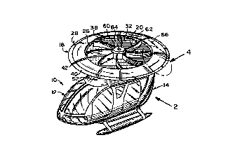
FIGURE l is a perspective view of the instant
invention incorporated into a helicopter.
FIGURE 2 is a side elevational view taken in the
direction of arrow 2 in Figure l.
FIGURE 3 is a top view of the circular wing
assembly per se taken in the direction of arrow 3 in
Figure 2.
FIGURE 4 is an enlarged perspective view of a
portion of the circular winy assembly as ; n~ ted by
arrow 4 in Figure l.
FIGURE 5 is a cross sectional view taken along line
5-5 in Figure 3.
FIGURE 6 is a cross sectional perspective view of a
modified circular wing assembly.

- ' ` ~
W096/07586 pcT~ss5lll2o3
1 99278
FIGURE 7 is a perspective view of the instant
invention incorporated into an autogiro.
Det~iled Descript;on of the P~eferred ~hodim~nts
Turning now descriptively to the drawings, in which
similar reference characters denote s;~il~r elements
throughout the several views, Figures 1 and 2 illustrate
a circular wing aircraft 10 in the form of a helicopter
12, comprising a fuselage 14 and a circular wing
assembly 16. A structure 18 is for mounting the
circular wing assembly 16 above the fuselage 14 in a
stationary manner. An air impeller unit 20 is
rotatively carried within the circular wing assembly 16.
A device 22 is for driving the air impeller unit 20 to
rotate about a central axis 24 within the circular wing
assembly 16, so as to provide lift and flight movement
while yaw control is maintAi ne~ .
The circular wing assembly 16, as best seen in
Figures 3 through 6, consists of a lower disc wing 26
and an upper ring wing 28. A plurality of wing mounts
30, are rA~ ly spaced apart about the central axis 24
and affixed between a top surface 32 of the lower disc
wing 26 and a bottom surface 34 of the upper ring wing
Z8.
The upper ring wing 28 is airfoil-shaped 36 in a
cross section and is sized to overlap the perimeter 38
of the lower disc wing 26. The upper ring wing 28
contains a plurality of sect; Q~l flaps 40 that are

W096/07s86 . PCT~Sg5/11203
1 99278
_4_
independently controllable about the outer circumference
42, for better lift and maneuverability. Each wing
mount 30 is airfoil- shaped 44 in cross section and
includes a movable flap 46 at its outer edge 48, to
increase and decrease a twisting force for yaw control.
The mounting structure 18 includes a plurality of
suspension members 50 rA~;~lly spaced apart about the
central axis 24. Each suspension membn member 50 extends
between a top surface 52 of the fuselage 14 and a bottom
IQ surface 54 of the lower disc wing 26. Each suspension
member 50 is independently length adjustable. The
circular wing assembly 16 can be tilted in any direction
relative to the fuselage 14, thus allowing the fuselage
14 to stay level in horizontal flight. A first rubber
shock absorber connector 56 is at the top surface 52 of
the fuselage 14. A second rubber shock absorber
connector 58 is at the bottom surface 54 of the lower
disc wing 26, so that vibration can be reduced,
resulting in a low noise level in the fuselage 14.
The air impeller unit 20 contains a hub 60, with a
plurality of curved blades 62 ext~n~;ng rA~;Ally from
the hub 60. A drive shaft 64 extends from the hub 60
through the central axis 24 to the driving device 22.
The curved blades 62 can rotate with the hub 60 on the
25 drive shaft 64, to draw air from the top and blow the !.
air out at a high velocity in radial directions over the
top surface 32 of the lower disc wing 26. This creates
a low pressure zone on the top surface 32 with static

W096/07586 ~ PCT~Sg5/11203
` .` 2 ~ 9~278
air pressure beneath the lower disc wing 26, providing a
lifting force perpendicular to the botlom surface 54 of
the lower disc wing 26. The air is also blown above a
top surface 66 and below the bottom suxface 34 of the
upper ring wing 28, respectively creat:Lng an additional
lift.
The driving device 22 is an engine 68 directly
connected to the circular wing assembly 16 and coupled
to the drive shaft 64. The upper ring wing 28 can be
lo hollow, as shown in Figures 4 and 5, having an annular
chamber 70 therein to be used as a fuel tank, thereby
allowing maximum space within the fuselage 14 for a
payload.
Figure 7 shows a circular wing air.craft lOa in the
form of an autogiro 72, comprising a fuselage 74. A
pair of short fixed wings 76, each extend outwardly from
an opposite side at the middle of the i.uselage 74. A
pair of 5~hi 1; ~ers 78, each extend out;wardly from an
opposite side at the tail 80 of the fuæelage 74. A
rudder 82 extends upwardly from the tail 80 of the
fuselage 74. A pair of circular wing assemblies 16, are
each pivotally mounted and controlled on a distal free
end 84 of one short fixed wing 76. A pair of air
=~ .. . . . . = . . ,
impeller units 20, are each rotatively driven within one
circular wing assembly 16, to rotate about a central
axis 24 by an engine (not shown), so as to provide lift
and flight movement while yaw control is maint~ine~.

Dessin représentatif
Une figure unique qui représente un dessin illustrant l'invention.
États administratifs

2024-08-01 : Dans le cadre de la transition vers les Brevets de nouvelle génération (BNG), la base de données sur les brevets canadiens (BDBC) contient désormais un Historique d'événement plus détaillé, qui reproduit le Journal des événements de notre nouvelle solution interne.

Veuillez noter que les événements débutant par « Inactive : » se réfèrent à des événements qui ne sont plus utilisés dans notre nouvelle solution interne.

Pour une meilleure compréhension de l'état de la demande ou brevet qui figure sur cette page, la rubrique Mise en garde , et les descriptions de Brevet , Historique d'événement , Taxes périodiques et Historique des paiements devraient être consultées.

Historique d'événement

Description Date
Inactive : Regroupement d'agents 2013-10-24
Demande non rétablie avant l'échéance 2001-09-05
Le délai pour l'annulation est expiré 2001-09-05
Réputée abandonnée - omission de répondre à un avis sur les taxes pour le maintien en état 2000-09-05
Inactive : Acc. réc. RE - Pas de dem. doc. d'antériorité 1998-12-07
Requête d'examen reçue 1998-09-02
Toutes les exigences pour l'examen - jugée conforme 1998-09-02
Exigences pour une requête d'examen - jugée conforme 1998-09-02
Inactive : Notice - Entrée phase nat. - Pas de RE 1997-08-25
Inactive : CIB attribuée 1997-08-07
Inactive : CIB en 1re position 1997-08-07
Inactive : CIB attribuée 1997-08-07
Inactive : Correction au certificat de dépôt 1997-06-12
Exigences de dépôt - jugé conforme 1997-06-12
Demande publiée (accessible au public) 1996-03-14

Historique d'abandonnement

Date d'abandonnement Raison Date de rétablissement
2000-09-05

Taxes périodiques

Le dernier paiement a été reçu le 1999-09-03

Avis : Si le paiement en totalité n'a pas été reçu au plus tard à la date indiquée, une taxe supplémentaire peut être imposée, soit une des taxes suivantes :

  • taxe de rétablissement ;
  • taxe pour paiement en souffrance ; ou
  • taxe additionnelle pour le renversement d'une péremption réputée.

Veuillez vous référer à la page web des taxes sur les brevets de l'OPIC pour voir tous les montants actuels des taxes.

Historique des taxes

Type de taxes Anniversaire Échéance Date payée
Taxe nationale de base - petite 1997-03-05
TM (demande, 2e anniv.) - petite 02 1997-09-05 1997-09-03
TM (demande, 3e anniv.) - petite 03 1998-09-08 1998-09-02
Requête d'examen - petite 1998-09-02
TM (demande, 4e anniv.) - petite 04 1999-09-07 1999-09-03
Titulaires au dossier

Les titulaires actuels et antérieures au dossier sont affichés en ordre alphabétique.

Titulaires actuels au dossier
GABOR I. VASS
Titulaires antérieures au dossier
S.O.
Les propriétaires antérieurs qui ne figurent pas dans la liste des « Propriétaires au dossier » apparaîtront dans d'autres documents au dossier.
Documents

Pour visionner les fichiers sélectionnés, entrer le code reCAPTCHA :


Pour visualiser une image, cliquer sur un lien dans la colonne description du document. Pour télécharger l'image (les images), cliquer l'une ou plusieurs cases à cocher dans la première colonne et ensuite cliquer sur le bouton "Télécharger sélection en format PDF (archive Zip)" ou le bouton "Télécharger sélection (en un fichier PDF fusionné)".

Liste des documents de brevet publiés et non publiés sur la BDBC .

Si vous avez des difficultés à accéder au contenu, veuillez communiquer avec le Centre de services à la clientèle au 1-866-997-1936, ou envoyer un courriel au Centre de service à la clientèle de l'OPIC.


Description du
Document 
Date
(aaaa-mm-jj) 
Nombre de pages   Taille de l'image (Ko) 
Page couverture 1997-08-21 1 47
Description 1997-03-05 5 170
Abrégé 1997-03-05 1 63
Revendications 1997-03-05 3 91
Dessins 1997-03-05 3 150
Dessin représentatif 1997-08-21 1 14
Avis d'entree dans la phase nationale 1997-08-25 1 193
Accusé de réception de la requête d'examen 1998-12-07 1 172
Courtoisie - Lettre d'abandon (taxe de maintien en état) 2000-10-03 1 184
Taxes 1999-09-03 1 58
PCT 1997-03-05 6 249
Correspondance 1997-06-12 1 36
Taxes 1997-09-03 1 55
Taxes 1998-09-02 1 65