Note: Descriptions are shown in the official language in which they were submitted.
- 2 ~ 3 0
BLADE ASSEMBLY WITH SELF-BRAKING ~LAIL ~ulll~G ELEMENTS
BACKGROUND OF TB I~V~N1 10N
1. Field of the Invention
The present invention relates generally to rotary cutting
apparatus and more particularly, but not by way of limitation, to
cutting attachments for rotary cutting apparatus.
2. Brief Description of the Related Art.
The prior art is replete with various types of rotary cutting
apparatus and cutting attachments for such rotary cutting
apparatus. However, the prior art cutting attachments for such
rotary cutting apparatus have a number of disadvantages. For
example, many of the cutting attachments have inadequate skid
plates or have cutting blades which wear out quickly and which are
ineffective in cutting various types of vegetation, including
grasses, weeds and other materials. In addition, many of the
cutting attachments are not self-cleaning and collect debris during
9 ~ 3 ~
operation which adversely affects the efficiency of the rotary
cutting apparatus.
Other cutting attachments which are formed with skid plates
and/or are configured to be self-cleaning are expensive to
S manufacture, difficult to attach to various types of rotary cutting
apparatus, or require special hand tools to attach and remove the
cutting àttachment from the rotary cutting apparatus. Further, the
prior art cutting attachments are generally not interchangeable
between rotary cutting apparatus made by various manufacturers.
Therefore, a need exists for an improved cutting attachment
for rotary cutting apparatus which overcomes the afore-mentioned
problems of the prior art cutting attachments, and which enables
one to attach such cutting attachment to various rotary cutting
apparatus without the requirement of hand tools or modification of
the rotary cutting apparatus. It is to such a cutting attachment
that the present invention is directed.
BRIEF SUMMARY OF THE INVENTION
According to the present invention, a cutting attachment for
a rotary cutting apparatus is provided which can be easily and
quickly a~tached and removed from a variety of commercially
available rotary cutting apparatus without the use of tools or
modification of such rotary cutting apparatus. Broadly, the
cutting attachment is provided with a first body member, a second
body member and a plurality of pins spaced an equidistance apart
for connecting the first body member to the second body member to
4 3 ~
form a rigid body wherein at least a portion of the first and
second body members are spatially disposed a distance (x) apart,
each of the pins having a bearing surface substantially
corresponding in length to the distance (x) between the first and
second body members. The cutting attachment further includes a
connector for connecting the rigid body to a shaft or arbor of the
rotating cutting apparatus and a plurality of cutting members
connected to the pins such that the cutting members are rotatable
about the pins and axially movable along the bearing surface of the
pins to effect cooling of the bearing surface of the pins and
thereby enhance the life of the cutting members by reducing heat
and friction between the pins and the cutting members due to
movement of the cutting members about and along the bearing surface
of the pins.
Each of the cutting members is characterized as having a blade
portion and a head portion through which an aperture extends and
through which one of the pins extends for connecting the cutting
members to the pins and thus to the first and second body members
of the rigid body. Each of the pins is characterized as having a
first end, a medial portion which defines the bearing surface, and
a second end. The pins have a pin length (pl) and a pin diameter
(pd) such that, upon disposing one of the pins through the aperture
in the head portion of one of the cutting members and connecting
the first end of the pins to the first body member and the second
end of the pins to the second body member, the cutting members are
spatially disposed in the space or distance (x) between the first
~ ~943~
and second body members such that the bearing surface of each of
the pins is exposed in such distance (x).
The blade portion of each of the cutting members has a
thickness (tb~ and the head portion of each of the cutting members
has a thickness (th), each of which is less than the distance (x)
between the first and second body members; and the apertures in the
head portions of the cutting members have a diameter (ad) greater
than the pin diameter (pd) of the pins so that the cutting members
are permitted to rotate about and axially move along the bearing
o surface of the pins during operation of the rotary cutting
apparatus and thereby effect cooling of the bearing surface of the
pins and thus substantially reduce enlargement of the apertures in
the head portions of the cutting members.
In one embodiment, the cutting attachment for a rotary cutting
apparatus is further provided with a braking assembly for reducing
the speed of rotation of the cutting members when the cutting
members are rotated in response to actuation of the rotary cutting
apparatus. The braking assembly is disposed on the blade portion
of the cutting members; or the braking assembly is disposed on the
O first body member and/or the second body member of the rigid body
of the cutting attachment; or the braking assembly is disposed on
the blade portion of the cutting members and on the first body
member and/or the second body member of the rigid body of the
cutting attachment.
An object of the present invention is to provide an improved
cutting attachment for a rotating cutting apparatus.
~- 2 ~ 3 0
Another object of the present invention, while achieving the
before-stated object, is to provide a cutting attachment which can
be used on various models of rotary cutting apparatus without
substantial modification of the cutting attachment or the rotary
cutting apparatus and wherein the cutting blades are movable along
a bearing surface of the pins to effect cooling of the bearing
surface and thereby enhance the useful-life of the cutting blades
without interfering with the cutting efficiency of the cutting
blades.
Another object of the present invention, while achieving each
of the before-stated objects, is to provide an improved cutting
attachment which is economical to manufacture and which can be
readily attached to and removed from a rotary cutting apparatus
without the need of hand tools.
Yet another object of the present invention, while achieving
each of the before-stated objects, is to provide an improved
cutting attachment wherein the cutting blades can readily be
replaced by the user at the location of use without the need of
special tools or fear of improper installation.
Other objects, advantages and features of the present
invention will become apparent to those skilled in the art from a
reading of the following detailed description and appended claims.
4 3 ~
BRIEF DESCRIPTION OF THE DRAWINGS
Fig. 1 is a pictorial representation of a rotary cutting
apparatus having a cutting attachment of the present invention
connected thereto.
Fig. 2 is a perspective view of a lower side of- the cutting
attachment of the present invention connected to a threaded spindle
or arbor of a rotary cutting apparatus.
Fig. 3 is a top plan view of the cutting attachment of the
present invention.
o Fig. 4 is a plan view of a first side of a first body member
of a rigid body of the cutting attachment of the present invention.
Fig. 5 is a plan view of a second side of the first body
member of the rigid body of the cutting attachment of the present
invention.
~5 Fig. 6 is a plan view of a first side of a second body member
of the rigid body of the cutting attachment of the present
invention.
Fig. 7 is a plan view of a second side of the second body
member of the rigid body of the cutting attachment of the present
~0 invention.
Fig. 8 is a perspective, partially broken, exploded view of
the cutting attachment of the present invention.
Fig. 9 is a cross-sectional view of the cutting attachment of
Fig. 3 taken along lines 9-9.
11 9 ~ 4 3 n
Fig. 10 is a partially broken, side elevational view of the
cutting attachment of the present invention depicting vertical
movement of a cutting member along a bearing surface of a pin.
Fig. ll is a perspective view of the cutting attachment of the
present invention attached to a rotary cutting apparatus wherein
one of the cutting members has been displaced temporarily due to
the cutting member encountering an object during operation of the
rotary cutting apparatus.
Fig. 12 is a fragmental pictorial representation of a rotary
L0 - cutting apparatus having a cutting attachment of the present
invention connected thereto wherein cutting members of the cutting
attachment are provided with a braking assembly.
Fig. 13 is a perspective view of one of the cutting members of
the cutting attachment of Fig. 12.
Fig. 14 is an elevational end view of the cutting member of
Fig. 13.
Fig. 15 is a perspective view of another embodiment of a
cutting member having a braking assembly wherein the braking
assembly is disposed along a portion of an upper surface and a
lower surface of a blade portion of the cutting member.
Fig. 16 is an elevational end view of the cutting member of
Fig. 15.
Fig. 17 is a perspective view of another embodiment of a
cutting member having a braking assembly wherein the braking
assembly is disposed along a leading edge and a trailing edge of a
blade portion of the cutting member.
Fig. 18 is an elevational end view of the cutting member of
Fig. 17.
Fig. 19 is a fragmental pictorial representation of a rotary
cutting apparatus having another embodiment of a cutting attachment
of the present invention connected thereto wherein the cutting
attachment is provided with a braking assembly.
Fig. 20 is a plan view of a second side of a first body member
of a rigid body of the cutting attachment of Fig. 19.
Fig. 21 is a plan view of a second side of the second body
o member of the rigid body of the cutting attachment of Fig. 19.
Fig. 22 is a perspective view of the second body member of the
rigid body of the cutting attachment of Fig. 19 as viewed from the
second side thereof.
DETAILED DESCRIPTION OF THE INVENTION
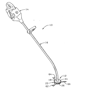
Referring now to the drawings, and more particularly to Fig.
1, a rotary cutting apparatus 10 is illustrated having a cutting
attachment 12 of the present invention mounted thereon. The rotary
cutting apparatus 10 is provided with a motor 14 and a frame shaft
0 tube 16. The frame shaft tube 16 extends forward and downward from
the motor 14, through a bend, to a generally lower vertical end 18
on which the cutting attachment 12 is mounted. The cutting
attachment 12 is connected to a drive shaft (not shown) housed
within the frame shaft tube 16 via a threaded arbor or spindle 20
~5 (Fig. 2) of the drive shaft of the rotary cutting apparatus 10. If
desired, the rotary cutting apparatus 10 can also be provided with
2 ~ 3 0
a debris shield (not shown) which extends about a portion of the
cutting attachment 12.
Rotary cutting apparatus, such as the rotary cutting apparatus
10, are well known in the art and are commercially available~
Thus, no further description of the rotary cutting apparatus 10 or
its operation is believed necessary to enable one skilled in the
art to understand the cutting attachment 12 of the present
invention.
Referring more specifically to Figs. 2-9, the cutting
o attachment 12 of the present invention is provided with a rigid
body 22 formed from a first body member 24 and a spatially disposed
second body member 26. The first body member 24 is provided with
a substantially planar first side 28, a second side 30 and a
generally vertical sidewall 32. A centrally disposed opening 34 is
L5 formed in the first body member 24 so as to extend between the
substantially planar first side 28 and the second side 30 of the
first body member 24. The second side 30 of the first body
member 24 is provided with a plurality of pin receiving holes 36,
38 and 40 formed therein which are spaced an equidistance apart and
disposed in close proximity to an outer peripheral surface of the
second side 30 of the first body member 24 substantially as shown
in Fig. 5.
The second body member 26, which is substantially a mirror
image of the first body member 24 with the exception noted herein,
is provided with a substantially planar first side 42, a second
side 44 and a generally vertical sidewall 46. A centrally disposed
2~g~430
opening 48 extends between the first side 42 and the second side 44
of the second body member 26 such that, in a connected pOSition of
the first and second body members 24 and 26 as will be described in
detail hereinafter, the centrally disposed opening 48 in the second
s body member 26 is axially aligned with the centrally disposed
opening 3~ in the first body member 24. The second side 44 of the
second body member 26 iS provided with a plurality of pin receiving
holes S0, 52 and 54 space~ an equidistance apart and disposed in
close proximity to an outer peripheral surface of the second side
0 44 of the second body me~ber 26 such that, in an assembled
position, each of the pin receiving holes 50, 52 and 54 in the
second side 44 of the second body member 26 iS alignable with one
of the pin receiving holes 36, 38 and 40 in the second side 30 of
the first body member 24.
The cutting attachment 12 further includes a plurality of pins
56, 58 and 60 for rotatably connecting a plurality of radially
extending cutting members 62, 64 and 66 to the rigid body 22 and
for connecting the first and second body members 24 and 26 to form
the rigid body 22 whereby at least a portion of the first and
second body members 24 and 26 are spatially disposed a distance (x)
so that the cutting members 62, 64 and 66 are rotatable about and
axially movable along the pins 56, 58 and 60 throughout the
distance (x) provided between the first and second body members 24
and 26 in a manner to be more fully described hereinafter. It
should be noted that while the cutting attachment 12 is depicted as
having three radially extending cutting members 62, 64 and 66
~ ~94~0
rotatably connected between the first and second body members 24
and 26 of the rigid body 22 by the pins 56, S8 and 60, two, four
or more of the radially extending cutting members can be rotatably
connected between the first and second body members 24 and 26 of
s the rigid body 22 without departing from the inventive concept
disclosed herein.
The pin 56 is an elongated, cylindrical-shaped member having
a first end 70, a medial portion 72 defining a bearing surface, and
a second end 74; the pin S8 is an elongated, cylindrical-shaped
o member having a first end 76, a medial portion 78 defining a
bearing surface, and a second end 80; and the pin 60 is an
elongated, cylindrical-shaped member having a first end 82, a
medial portion 84 defining a bearing surface, and a second end 86.
Thus, upon disposing the first end 70 of the pin 56 in the pin
L5 receiving hole 36 in the second side 30 of the first body member 24
and disposing the second end 74 of the pin S6 in the pin receiving
hole 50 in the second side 44 of the second body member 26, the
first end 76 of the pin 58 in the pin receiving hole 38 in the
second side 30 of the first body member 24 and the second end 80 of
the pin 58 in the pin receiving hole S2 in the second side 44 of
the second body member 26 and the first end 82 of the pin 60 in the
pin receiving hole 40 formed in the second side 30 of the first
body member 24 and the second end 86 of the pin 60 in the pin
receiving hole S4 formed in the second side 44 of the second body
2s member 26, the pins 56, 58 and 60 cooperate to secure the first
body member 24 to the second body member 26 to form the rigid body
3 ~
22 while maint~;~;ng at least a portion of the first body member 24
in a spatial relationship with the second body member 26 so that at
least a portion of the first body member 24 iS disposed the
predetermined distance ~x) from the second body member 26.
Each of the pins 56, 58 and 60 have a pin length (pl) and a
pin diameter (pd). The pin length (pl) of the pins S6, 58 and 60
is such that, in a connected position, the bearing surfaces defined
by the medial portions 72, 78 and 84 of~the pins 56, 58 and 60 are
exposed in the space formed between the first and second body
o members 24 and 26 of the rigid body 22 substantially as shown in
Figs. 9 and 10.
Each of the cutting members 62, 64 and 66 iS connected to one
of the pins 56, 58 and 60 so that when the rigid body 22 of the
cutting attachment 12 rotates about axis 88 (Fig. 9) the cutting
members are disposed in a vegetation cutting position. The cutting
members 62, 64 and 66 are ~ormed of a high-impact plastic or
similar composition and each of the cutting members 62, 64 and 66
is movable between an outwardly cutting position (Figs.1-3) and a
deflected, out of the way position when one of the cutting members,
o such as cutting member 62 strikes an object, such as a rock 90
(Fig. 11), during rotation of the cutting attachment 12 so that the
cutting members 62, 64 and 66 will not be damaged.
The cutting member 62 is provided with a blade portion 92 and~
a head portion 94 having an aperture 96 through which the pin 56
'5 extends for connecting the cutting member 62 to the pin 56 and thus
to the first and second body members 24 and 26 of the rigid body
12
- 2 ~ 3 ~
22. The blade portion 92 of the cutting member 62 iS provided with
a first or upper generally planar surface 98 and a second or lower
generally planar surface 100. The lower generally planar surface
100 is spatially disposed from the upper generally planar surface
98 (Fig. 9) and the blade portion 92 of the cutting member 62 is
further provided with cutting edges 102 and 104 which have a
substantially-V-shaped configuration with approximately equivalent
inclination angles (Fig. 3).
The cutting member 64 is also provided with a blade portion
.o 106 and a head portion 108 having an aperture 110 through which the
pin 58 extends for connecting the cutting member 64 to the pin 58
and thus to the first and second body members 24 and 26 of the
rigid body 22. The blade portion 106 of the cutting member 64 is
provided with a first or upper generally planar surface 112 and a
second or lower generally planar surface 114. The lower generally
planar surface 114 is spatially disposed from the upper generally
planar surface 112 and the blade portion 106 of the cutting member
64 is further provided with cutting edges 116 and 118 which have a
substantially V-shaped configuration with approximately equivalent
~0 inclination angles (Fig. 3).
The cutting member 66 is provided with a blade portion 120 and
a head portion 122 having an aperture 124 through which the pin 60
extends for connecting the cutting member 66 to~the pin 60 and thus
to the first and second body members 24 and 26 of the rigid body
~5 22. The blade portion 120 of the cutting member 66 iS provided
with a first or upper generally planàr surface 126 and a second or
3 ~
lower generally planar surface 128. The lower generally planar
surface 128 iS spatially disposed from~the upper generally planar
surface 126 and the blade portion 120 of the cutting member 66 is
further provided with cutting edges 130 and 132 which have a
S substantially V-shaped configuration with approximately equivalent
inclination angles (Fig. 3).
The cutting members 62, 64 and 66 are substantially identical
in construction and each has a thickness (t) less than the distance
(x) between the first and second body members 24 and 26 so that the
0 cutting members 62, 64 and 66 are freely rotatable upon the bearing
surface of the pins 56, 58 and 60 while at the same time being
permitted to move axially along the bearing surface throughout the
distance (x) between the first and second body members 24 and 26.
That is, the blade portions 92, 106 and 120 of the cutting members
62, 64 and 66 each has a thickness (tb) and the head portions 94,
108 and 122 of the cutting members 62, 64 and 66 each have a
thickness (th) wherein the thickness (th) is greater than the
thickness (tb), but each of the thickness (th) and (tb) is less
than the distance (x) between the first and second body members 24
o and 26. In addition, each of the apertures 96, 110 and 124 formed
in the head portions 94, 108 and 122 of the cutting members 62, 64
and 66 each have a diameter (ad) greater than the pin diameter (pd)
of the pins 56, 58 and 60 so that upon positioning the pins 56, 58
and 60 through the apertures 96, 110 and 124 in the head portions
94, 108 and 122 of the cutting members 62, 64 and 66, the cutting
members 62, 64 and 66 are permitted to rotate about and axially
14
3 Q
move along the bearing sUrface of the pins 62, 64 and 66 during
operation of the rotary cutting apparatus 10 and thereby effect
cooling of the bearing surface of the pins 62, 64 and 66 and thus
substantially reduce enlargement of the apertures 96, 110 and 124
in the head portions 94, 108 and 122 of the cutting members 62, 64
and 66. Further, because of the configuration of the cutting
members 62, 64 and 66 and depending upon the direction of rotation
of the cutting attachment 12, either of-the cutting edges, such as
the cutting edges 102 and 104, of the cutting member 62 can be
o employed as the leading or trailing edge and such can be reversed
by merely disassembling the rigid body 22 and turning the cutting
member, such as the cutting member 62, upside down after the
cutting attachment 12 has been removed from the rotary cutting
apparatus 10.
The rigid body 22 having the cutting members 62, 64 and 66
connected thereto via the pins 56, 58 and 60, can be connected to
the threaded arbor or spindle 20 of the rotary cutting apparatus 10
(Fig. 2~ via connector 134 of the cutting attachment 12. As
previously stated, the first and second body members 24 and 26 are
substantially identical in construction with the exception that the
planar first side 42 of the second connector member 26 is provided
with a non-circular recess 136 which extends about the centrally
disposed opening 48 in the second body member 26. As will be more
fully described hereinafter, the non-circular recess 136 formed in
the planar first side 42 of the second body member 26 is configured
to receive a portion of the connector 134 to facilitate connection
of the rigid body 22 formed from the first and second body members
~ 24 and 26 to the threaded arbor or spindle 20 of the rotary cutting
apparatus 10 by hand and without the use of tools.
As more clearly shown in Figs. 8 and 9~ the connector 134 is
provided with a non-circular head portion 138 and a shaft or barrel
portion 140 which extends substantially normal to the non-circular
head portion 138. Internally disposed threads 142 extend through
the non-circular head portion 138 and the shaft portion 140
substantially as shown. The non-circular head portion 138, which
is provided with a configuration substantially corresponding to the
configuration of the non-circular recess 136 formed about the
centrally disposed opening 48 in the first side 42 of the second
body member 26, has a height 143 substantially corresponding to the
depth of the non-circular recess 136 so that when the connector 134
is disposed within the aligned centrally disposed openings 34 and
48 of the first and second body members 24 and 26, the non-circular
head portion 138 of the connector 134 is substantially coplanar
with the planar first side 42 of the second body member 26.
Further, the connector 134 is provided with a length 144 such that
when the connector 134 is disposed within the centrally disposed
openings 34 and 48 of the first and second body members, a distal
end 145 of the,shaft 140 is substantially coplanar with the first
ends 70, 76 and 82 of the pins 56, 58 and 60.
The diameter and pitch of the internally disposed threads 142
extending through the non-circular head portion 138 and the shaft
portion 140 of the connector 134 can vary and will be dependent
16
4 3 Q
upon the ~;~m~ter and pitch of the threaded arbor or spindle 20 of
the rotary cutting apparatus 10 to which the cutting attachment 12
i8 to be connected. Thus, to provide the desired versatility to
the cutting attachment 12 so that the cutting attachment 12 can be
attached to a variety of different commercially available rotary
cutting apparatus 10, the only modification to the attachment 12
required to provide such versatility is to provide the connector
138 with an internal diameter and threàds of the desired pitch to
correspond to the threaded arbor or shaft 20 of the rotary cutting
apparatus 10.
To enhance the rigidity of the rigid body 22 of the rotary
cutting attachment 12, as well as to enhance the cutting attachment
12 by providing a self-cleaning feature, the first body member 24
is provided with a plurality of radially extending bosses 146, 148
and 150 which extend from the centrally dispos~d opening 34 in the
first body member 24 to the sidewall 32 of the first body member
24. The bosses 146, 148 and 150 of the first body member 24 each
contain one of the pin receiving holes 36, 38 and 40 of the first
body member 24 substantially as shown in Fig. 5. Further, in order
to prevent undesired restriction of the rotation of the cutting
members 62, 64 and 66 during rotation of the cutting attachment 12,
the bosses 146, 148 and 150 are substantially coplanar with an edge
152 (Fig. 8~ of the sidewall 32 of the first body member 24.
Similarly, the second body member 26 is provided with a
plurality of radially extending bosses 154, 156, and 158 which
extend from the centrally disposed opening 48 in the second body
, 3 ~
member 26 to the sidewall 46 of the second body member 26. The
bosses 154, 156 and 158 each contain one of the pin receiving holes
50, 52 and 54 of the second body member 26 substantially as shown
in Figs. 7 and 8. Further, in order to prevent undesirable
restriction of the rotation of the cutting members 62, 64 and 66
during rotation of the cutting attachment 12, the bosses 154, 156
and 158 are substantially coplanar with an edge 160 (Fig. 8) of the
-sidewall 46 of the second body member 26.
To prevent improper assembly of the first and second body
o members 24 and 26 by insuring that the pins 56, 58 and 60 are
disposed in their respective pin receiving holes, namely, pin
receiving holes 36 and 50, 38 and 52, and 40 and 54 during assembly
of the cutting attachment 12, the first-body member 24 is provided
with pin guiding bosses 162, 164 and 166 which extend between the
~5 bosses 146, 148 and 150 substantially as shown in Fig. 5; and the
second body member is provided with pin guiding bosses 168, 170 and
172 which extend between the bosses 154, 156 and 158 substantially
as shown in Fig. 7. That is, the pin guiding boss 162 of the first
body member 24 is an arcuate segment extending between the boss 146
and the boss 148 so as to be disposed along a radius a distance
from the center of the centrally disposed opening 34 in the first
body member 24 and the pin receiving holes 36 and 38 formed in the
bosses 146 and 148; the pin guiding boss 164 is an arcuate segment
extending between the boss 148 and the boss 150 so as to be
disposed along a radius a distance from the center of the centrally
disposed opening 34 in the first body member 24 and the pin
3 al
receiving holes 38 and 40 formed in the bosses 148 and 150; and the
pin guiding boss 166 is an arcuate segment extending between the
boss 150 and the boss 146 so as to be disposed along a radius a
distance from the center of the centrally disposed opening 34 in
the first body member 24 and the pin receiving holes 40 and 36
formed in the bosses 150 and 146.
Similarly, the pin guiding boss 168 of the second body member
26 is an arcuate segment extending between the boss lS4 and the
boss 156 so as to be disposed along a radius a distance from the
o center of the centrally disposed opening 48 in the second body
member 26 and the pin receiving holes 50 and 52 formed in the
bosses 154 and 156; the pin guiding boss 170 is an arcuate segment
extending between the boss 156 and the boss 158 so as to be
disposed along a radius a distance from the center of the centrally
disposed opening 48 in the second body member 26 and the pin
receiving holes 52 and 54 formed in the bosses 156 and 158; and the
pin guiding boss 172 is an arcuate segment extending between the
boss 158 and the boss 154 so as to be disposed along a radius a
distance from the center of the centrally disposed opening 48 in
o the second body member 26 and the pin receiving holes 54 and 50
formed in the bosses 158 and 154.
To enhance rigidity of the rigid body 22, especially when the
cutting attachment 12 is connected to the threaded arbor or spindle
20 of the rotary cutting apparatus 10, the second side 30 of the
~5 first body member 24 is provided with a first support boss 174
which extends about the centrally disposed opening 34 of the first
3 ~
body member 24; and the second side 44 of the ~econd body member 26
is provided with a second support boss 176 which extends about the
centrally disposed opening 48 of the second body member 26. The
first support boss 174 extends outwardly from the first body member
24 a distance approximately equal to one half (1/2~ of the distance
(x~ between the first and second body members 24 and 26.
Similar-ly, the second support boss 176 extends outwardly from the
second body member 26 a distance approximately equal to one half
(1/2) of the distance (x) between the first and second body members
0 24 and 26. Thus, in an assembled position of the first and second
body members 24 and 26, the first support boss 174 iS aligned with
and disposed substantially adjacent the second support boss 176
such that the first and second support bosses 174 and 176 cooperate
to support the portion of the first and second body members 24 and
26 extending about the centrally disposed openings 34 and 48 in the
first and second body members 24 and 26, respectively. The first
and second bosses 174 and 176, in cooperation with the pins 56, 58
and 60, maintain the first and second body members 24 and 26 in the
desired spatial relation so that the cutting members 62, 64 and 66
~0 are freely rotatable upon the bearing surface of the pins 56, 58
and 60 while at the same time being movable axially along the
bearing surface of the pins 56, 58 and 60 throughout the distance
(x) between the first and second body members 24 and 26.
In operation and use, the cutting attachment 12 is connected
'5 to the threaded arbor or spindle 20 of the rotary cutting apparatus
10 by threading the connector 134 (which is sized and dimensioned
to have the proper internal diameter and thread pitch to matingly
engage with the threaded arbor-or spindle 20) onto the threaded
arbor or spindle 20. The cutting attachment 12 can then be
operated in close proximity to the ground in the area in which
vegetation is to be cut. The cutting members 62, 64 and 66 will be
rotated as the cutting attachment 12 is rotated and, in the event
a hard object is struck, such as by cutting member 62, the cutting
member 62 will either be deflected upwardly as it moves axially
along the bearing surface of the connector pin 70 if the member 62
0 can ride over the object or, if the object is too large, the
cutting member 62 will be deflected out of the way as shown in Fig.
11. As soon as the object has been cleared, the cutting member 62
wili return to its normal position by centrifugal force.
It should be noted that the configuration and smooth planar
first side 42 of the second body member 26, in combination with the
sidewalls 32 and 44 of the first and second body members 24 and 26
prevent the rigid body member from engaging or snagging objects
encountered by the cutting attachment 12. As a result, the
configuration of the first and second body members 24 and 26 enable
0 the cutting attachment 12 to skid over objects encountered by it
while permitting the cutting members 62, 64 and 66 to rotate about
and move axially along the bearing surface of the pins 56, 58 and
60 and thereby effect cooling of the bearing surface of the pins
56, 58 and 60. The rotational and axial movement of the cutting
members 62, 64 and 66 along the bearing surface of the pins 56, 58
and 60 substantially enhance the life of the cutting members 62, 64
3 0
and 66 by reducing heat and friction between the pins 56, 58 and 60
and the cutting members 62, 64 and 66 due to movement of the
cutting members 62, 64 and 66 about and along the bearing surface
of the pins 56, 58 and 60.
Further the interconnection of the first and second body
members 24 and 26 to form the rigid body 22 of the cutting
attachment 12 provides a self-cleaning effect so as to pre~ent
cuttings and debris from depositing within the space formed between
the first and second body members 24 and 26 and thereby interfere
o with the effective operation of the rotary cutting apparatus 10.
Referring now to Fig. 12, the rotary cutting apparatus 10 is
illustrated having a cutting attachment 12a constructed in
accordance with the present invention mounted thereon. The cutting
attachment 12a is connected to the drive shaft (not shown) of the
L5 rotary cutting apparatus 10 which is housed within the frame shaft
tube 16 via the threaded arbor or spindle 20 (Fig. 2~ of the drive
shaft of the rotary cutting apparatus 10. If desired, the rotary
cutting apparatus 10 can also be provided with a debris shield (not
shown) which extends about a portion of the cutting attachment 12a.
The cutting attachment 12a is provided with a rigid body 22a
formed from a first body member 24a and a spatially disposed second
body member 26a. A plurality of radially extending cutting members
Z14, 216 and 218 are rotatably connected to the rigid body 22a by
pins (not shown). The rigid body 22a, the interconnection of the
first and second body members 24a and 26a and the connection of the
radially extending cutting members 214, 216 and 218 to the rigid
22
~ ~ 4 ~ ~
body 22a, are substantially identical to the rigid body 22, the
interconnection of the first and second body members 24 and 26 and
the connection of the radially extending cutting member 62, 64 and
66 to the rigid body 22 herein before described in detail with
reference to Figs. 2-10. Thus, no further description of the rigid
body 22a, the interconnection of the first and second body members
24a and 26a or the connection of the radially extending cutting
members 214, 216 and 218 to the rigid body 22a is believed
necessary. It should be noted that while the cutting attachment
o 12a is depicted as having three radially extending cutting members
214, 216 and 218 rotatably connected between the first and second
body members 24a and 26a of the rigid body 22a, two, four or more
of the radially extending cutting members can be rotatably
connected between the first and second body members 24a and 26a of
the rigid body 22a without departing from the inventive concept
disclosed herein.
The radially extending cutting members 214, 216 and 21B are
identical in construction as the radially extending cutting members
62, 64 and 66 hereinbefore described with the exceptions herein
0 after described. Further, the cutting members 214, 216 and 218 are
identical in construction and function. Thus, only the cutting
member 214 will be described in detail hereinafter with reference
to Figs. 13 and 14.
The cutting member 214 is provided with a blade portion 220
~S and a head portion 222. The head portion 222 has an aperture 224
through which a pin (such as pin 56 of Fig. 8) extends for
23
3 ~
connecting the cutting member 214 to the first and second body
members 24a and 26a of the rigid body 22a. The blade portion 220
of the cutting member 214 is provided with a first or upper
generally planar surface 226 and a second or lower generally planar
s surface 228. The lower generally planar surface 228 is spatially
disposed from the upper generally planar surface 226 and the blade
portion 220 of the cutting member 214 is further provided with
cutting edges 230 and 232 which have~a substantially V-shaped
configuration with approximately equivalent inclination angles.
o The cutting member 214 is further provided with a rib member
234 disposed along at least a portion of the upper generally planar
surface 226 of the blade portion 220 which functions as a brake to
reduce the speed of rotation of the cutting member 214 when the
cutting member 214 is rotated in response to actuation of the
rotary cutting apparatus 10. One end 236-of the rib member 234 is
disposed a distance 237 from the head portion 222 of the cutting
member 214 so that the rib member 234 does not interfere with the
rotational connection of the cutting member 214 to the rigid body
22a of the cutting attachment 12a. The rib member 234 extends
o along at least a portion of a longitudinally extending axis 238 of
the blade portion 220 of the cutting member 214 such that a second
end 240 of the rib member 234 terminates near a distal end 242 of
the blade portion 220 of the cutting member 214 substantially as
shown. It should be understood, however, that the second end 240
s of the rib member 234 can be disposed substantially adjacent the
distal end 242 of the blade portion 220 of the cutting member 214.
24
The height of the rib member 234 can vary widely and will
depend on the amount of resistance desired to effectively obtain
the desired braking action. Further, while the rib member 234 has
been shown as being disposed along the upper generally planar
s surface 226 of the blade portion 220 of the cutting member 214, it
is to be understood that the rib member 234 can be disposed along
the lower generally planar surface 228 of the blade portion 220 of
the cutting member 214. Further, because of the configuration of
the cutting member 214 and depending upon the direction of rotation
o of the cutting attachment 12a, either of the cutting edges 230 and
232 of the cutting member 214 can be employed as the leading or
trailing edge and such can be reversed by merely disassembling the
rigid body 22a and turning the cutting member 214 upside down after
the cutting attachment 12a has been remo~ed from the rotary cutting
apparatus 10.
Referring now to Figs. 15 and 16, another embodiment of a
cutting member 250 is illustrated. The cutting member 250 can be
used in place of the cutting members 62, 64 and 66 of the cutting
attachment 12 or the cutting members 214, 216 and 218 of the
~0 cutting attachment 12a. The cutting member 250 is provided with a
blade portion 252 and a head portion 254. The head portion 254 has
an aperture 2s6 through which a pin (such as pin 56 of Fig. 8)
extends for connecting the cutting member 250 to a first and second
body member of a rigid body, such as the first and second body
~s members 24a and 26a of the rigid body 22a.
3 ~
The blade portion 252 of the cutting member 250 is provided
with a first or upper generally planar surface 258 and a second or
lower generally planar surface 260. The lower generally planar
surface 260 is spatially disposed from the upper generally planar
surface 258 and the blade portion 252 of the cutting member 250 is
further provided with cutting edges 262 and 264 which have a
substantially V-shaped-configuration with approximately e~uivalent
inclination angles.
The cutting member 250 is further provided with a rib member
o 266 disposed along at least a portion of the upper generally planar
surface 258 of the blade portion 252 and a rib member 268 disposed
along at least a portion of the lower generally planar surface 260.
The rib members 266 and 268 function as a brake to reduce the speed
of rotation of the cutting member 250 when the cutting member 250
is rotated in response to actuation of the rotary cutting apparatus
10 .
One end 270 of the rib member 266 is disposed a distance 271
from the head portion 254 of the cutting member 250 and one end
(not shown) of the rib member 268 is likewise disposed a similar
o distance from the head portion 254 of the cutting member 250 so
that the rib members 266 and 268 do not interfere with the
rotational connection of the cutting member 250 to a rigid body
member, such as the rigid body 22a of the cutting attachment 12a.
The rib members 266 and 268 extend along at least a portion of a
longitudinally extending axis 272 of the blade portion 252 of the
cutting member 250 such that a second end 274 of the rib member 266
26
3 ~
and a second end 276 of the rib member 268 terminate near a distal
end 278 of the blade portion 252 of the cutting member 250
substantially as shown. It should be understood, however, that the
second ends 274 and 276 of the rib members 266 and 268 can be
disposed substantially adjacent the distal end 278 of the blade
portion 252 of the cutting member 250.
The height of the rib members 266 and 268 can vary widely and
will depend on the amount of resistance desired to effectively
obtain the desired braking action. Further, because of the
configuration of the cutting member 250, either of the cutting
edges 262 and 264 of the cutting member 250 can be employed as the
leading or trailing edge and such can be reversed by merely
disassembling the rigid body to which the cutting member 250 is
rotatably connected, such as the rigid body 22a, and turning the
cutting member 250 upside down after the cutting attachment 12a has
been removed from the rotary cutting apparatus 10.
Referring now to Figs. 17 and 18, another embodiment of a
cutting member 280 is illustrated. The cutting member 280 can be
used in place of the cutting members 62, 64 and 66 of the cutting
0 attachment 12 or the cutting members 214, 216 and 218 of the
cutting attachment 12a. The cutting member 280 is provided with a
blade portion 282 and a head portion 284. The head portion 284 has
an aperture 286 through which a pin (such as pin 56 of Fig. 8)
extends for connecting the cutting member 280 to a first and second
body member of a rigid body, such as the first and second body
members 24a and 26a of the rigid body 22a.
The blade portion 282 of the cutting member 280 is provided
with a first or upper generally planar surface 288 and a second or
lower generally planar surface 290. The lower generally planar
surface 290 is spatially disposed from the upper generally planar
surface 288 and the blade portion 282 of the cutting member 280 is
further provided with substantially V-shaped recessed edges 292 and
294 with approximately equivalent inclination angles substantially
as ghown. The substantially V-shaped recessed edges 292 and 294
function as cutting edges and as a brake to reduce the speed of
rotation of the cutting member 280 when the cutting member 280 is
rotated ir. response to actuation of the rotary cutting apparatus
10. Because of the configuration of the cutting member 280, either
of the substantially V-shaped recessed edges 292 and 294 of the
cutting member 280 can be employed as the leading or trailing edge
and such can be reversed by merely disassembling the rigid body to
which the cutting member 280 is rotatably connected, such as the
rigid body 22a, and turning the cutting member 280 upside down
after the cutting attachment 12a has been removed from the rotary
cutting apparatus 10.
Referring now to Fig. 19, a cutting attachment 12b of the
present invention is illustrated connected to the rotary cutting
apparatus 10. The connection of the cutting attachment 12b to the
rotary cutting apparatus 10 is substantially identical to the
attachment of the cutting attachment 12 to the rotary cutting
apparatus 10 heretofore described with reference to Fig. 1. The
cutting attachment 12b is illustrated as having a plurality of
28
Q
cutting members radially extending therefrom, such as the cutting
members 62, 64 and 66. However, it should be understood that the
cutting members can have the configuration of the cutting members
214, 216 and 218 of the cutting attachment 21~ heretofore described
with reference to Figs. 12-14, or the configuration of the cutting
member 250 heretofore described with reference to Figs. 15 and 16,
or the configuration of the cutting member 280 heretofore described
with reference to Figs. 17 and 18 without departing from the
inventive concept disclosed herein.
o The cutting members 62, 64 and 66 are connected to a rigid
body member 22b of the cutting attachment 12b in the same manner in
which the cutting members 62, 64 and 66 are connected to the rigid
body member 22 of the cutting attachment-12 hereinbefore described;
and the construction of the rigid body member 22b is substantially
identical to that of the rigid body member 22 with the exceptions
hereinafter noted.
The rigid body member 22b of the cutting attachment 12b is
formed from a first body member 24b and a spatially disposed second
body member 26b. The first body member 24b is provided with a
~o substantially planar first side 28b, a second side 30b and a
generally vertical sidewall 32b. A centrally disposed opening 34b
is formed in the first body member 24b so as to extend between the
substantially planar first side 28b and the second side 30b of the
first body member 24b. The second side 30b of the first body
~s member 24b is provided with a plurality of pin receiving holes 36b,
38b and 40b formed therein which are spaced an equal distance apart
29
3 ~
and disposed in close proximity to an outer peripheral surface of
the second side 30b of the first body member 24b substantially as
shown in Fig. 20.
Referring now to Figs. 21 and 22, the second body member 26b,
S which is substantially a mirror image of the first body member 24b
with the exceptions noted herein, is provided with a substantially
planar first side 42b, a second side 44b and a generally vertical
sidewall 46b. A centrally disposed opening 48b extends between the
first side 42b and the second side 44b of the second body member
o 26b such that, in a connected position of the first and second body
members 24b and 26b, the centrally disposed opening 48b in the
second body membel 26b is axially aligned with the centrally
disposed opening 34b in the first body member 24b. The second side
44b of the second body member 26b is provided with a plurality of
pin receiving holes SOb, 52b and S4b spaced an equal distance apart
and disposed in close proximity to an outer peripheral surface of
the second side 44b of the second body member 26b such that, in an
assembled position, each of the pin receiving holes 50b, 52b and
54b in the second side 44b of the second body member 26b are
aligned with one of the pin receiving holes 36b, 38b and 40b in the
second side 3Ob of the first body member 24b. The second body
member 26b is further provided with a non-circular recess 136b
!shown in phantom in Fig. 21) in the first planar side 42b of the
second body member 26b which is configured to receive a portion of
2S the connector (not shown) to facilitate connection of the rigid
body 22b formed from the first and second body members 24b and 26b
to the threaded arbor or spindle 20 of the rotary cutting apparatus
10 by hand and without the use of tools as heretofore discussed
with reference to the attachment of the cutting attachment 12 to
the rotary cutting apparatus 10.
To enhance the rigidity of the rigid body 22b of the rotary
cutting attachment 12b, the first body member 24b is provided with
radially extending bosses 146b, 148b and 150b which extend from the
centrally disposed opening 34b in the flrst body member 24b to the
sidewall 32b of the first body member 24b. The boss 146b contains
a pin receiving hole 36b, the boss 148b contains a pin receiving
hole 38b and the boss 150b contains a pin receiving hole 40b
substantially as shown in Fig. 20. To prevent undesired
restriction of the rotation of the cutting members 62, 64 and 66
during rotation of the cutting attachment 12b, the bosses 146b,
148b and 150b are substantially coplanar with an edge 152b of the
sidewall 32b of the first body member 24b.
Similarly, the second body member 26b is provided with a
plurality of radially extending bosses 154b, 156b, and 158b which
extend from the centrally disposed opening 48b in the second body
member 26b to the sidewall 46b of the second body member 26b. The
boss 154b contains a pin receiving hole 50b, the boss 156b contains
a pin receiving hole 52b and the boss 158b contains a pin receiving
hole 54b substantially~as shown in Figs. 21 and 22. To prevent
undesirable restriction of the rotation of the cutting members 62,
64 and 66 during rotation of the cutting attachment 12b, the bosses
154b, 156b and 158b are substantially coplanar with an edge 160b
(Fig. 22) of the sidewall 46b of the second body member 26b.
To insure proper alignment of the first and second body
members 24b and 26b during the assembly of the rigid body 22b, the
s first body member 24b is provided with a plurality of pin guiding
bosses 162b, 164b and 166b which extend between the bosses 146b,
148b and l50b substantially as shown in Fig. 20; and the second
body member 26b is provided with a plurality of pin guiding bosses
168b, 170b and 172b which extend between the bosses 154b, 156b and
o 158b substantially as shown in Figs. 21 and 22. That is, the pin
guiding boss 162b of the first body member 24b is an arcuate
segment extending between the boss 146b and the boss 148b so as to
be disposed along a radius a distance from the center of the
centrally disposed opening 34b in the first body member 24b and the
~5 pin receiving holes 36b and 38b formed in the bosses 146b and 148b;
the pin guiding boss 164b is an arcuate segment extending between
the boss 148b and the boss 150b so as to be disposed along a radius
a distance from the center of the centrally disposed opening 34b in
the first body member 24 and the pin receiving holes 38 and 40
~o formed in the bosses 148b and l50b; and the pin guiding boss 166b
is an arcuate segment extending between the boss 150b and the boss
146b so as to be disposed along a radius a distance from the center
of the centrally disposed opening 34b in the first body member 24b
and the pin receiving holes 40b and 36b formed in the bosses 150b
and 146b.
3 ~
Similarly, the pin guiding boss 168b of the second body member
26b is an arcuate segment extending between the boss 154b and the
boss 156b so as to be disposed along a radius a distance from the
center of the centrally disposed opening 48b in the second body
S member 26b and the pin receiving holes 50b and 52b formed in the
bosses lS4b and 156b; the pin guiding boss 170b is an arcuate
segment extending between the boss 156b and the boss 158b so as to
be disposed along a radius a distancé from the center of the
centrally disposed opening 48b in the second body member 26b and
o the pin receiving holes 52b and 54b formed in the bosses 156b and
158b; and the pin guiding boss 172b is an arcuate segment extending
between the bo~s 158b and the boss 154b so as to be disposed along
a radius a distance from the center -of the centrally disposed
opening 48b in the second body member 26b and the pin receiving
holes 54b and ~Ob formed in the bosses 158b and 154b.
To enhance rigidity of the rigid body 22b, especially when the
cutting attachment 12b is connected to the threaded arbor or
~pindle of the rotary cutting apparatus 10, the second side 30b of
the first body member 24b is provided with a first support boss
~0 174b which extends about the centrally disposed opening 34b of the
first body member 24b; and the second side 44b of the second body
member 26b is provided with a second support boss 176b which
extends about the centrally disposed opening 48b of the second body
member 26b. The first support boss 174b extends outwardly from the
first body member 24b a distance approximately equal to one half
(1/2) of the distance x (hereinbefore described) between the first
and second body members 24b and 26b. Similarly, the second support
boss 176b extends outwardly from the second body member 26b a
distance approximately equal to one half (1/2) of the distance x
between the first and second body members 24b and 26b. Thus, in an
assembled position of the first and second body members 24b and
26b, the first support boss 174b is aligned with and disposed
substantially adjacent the second support boss 176b such that the
first and second support bosses 174b ana 176b cooperate to support
the portion of the first and second body members 24b and 26b
extending about the centrally disposed openings 34b and 48b in the
first and second body members 24b and 26b, respectively. The
first and second bosses 174b and 176b, in cooperation with pins,
such as the pins 56, 58 and 60 hereinbefore described, maintain the
first and second body members 24b and 26b in the desired spatial
relation so that the cutting members 62, 64 and 66 are freely
rotatable upon the bearing surface of the pins while at the same
time being movable axially along the bearing surface of the pins
throughout the distance (x) between the first and second body
members 24b and 26b.
The rigid body 22b of the cutting attachment 12b is further
provided with a brake assembly 300 for reducing the speed of
rotation of the rigid body 22b, and thus the cutting members 62, 64
and 66 when the rigid body 22b is rotated in response to actuation
of the rotary cutting apparatus 10. The brake assembly 300
comprises a plurality of radially extending rib members 302, 304
and 306 disposed between the radially extending bosses 146b, 148b
34
3 ~
and 150b of the first body member 24b and a plurality of radially
extending rib members 308, 310 and 312 disposed between the
radially extending bosses 154b, 156b and 158b of the second body
member 26b. The ri~ members 302, 304 and 306 of the first body
member 24b extend from the first support boss 174b disposed about
the centrally disposed opening 34b in the first body member 24b to
the sidewall 32b of the first body member 24b.and are.substantially
- coplanar with the edge 152b of the sidewall 32b of the first body
member 24b and thus the bosses 146b~ 148b and 150b. Similarly, the
.0 rib members 308, 310 and 312 of the second body member 26b extend
from the second support boss 176b disposed about the centrally
disposed opening 48b in the second body member 26b to the sidewall
46b of the second body member 26b and-are substantially coplanar
with the edge 160b of the sidewall 46b of the second body member
s 26b and thus the bosses 154b, 156b and 158b substantially as shown
in Fig. 22.
It should be understood that the cutting attachment 12b is
assembled in substantially the same manner as the cutting
attachment 12 hereinbefore described in detail with reference to
)o Figs. 2-8. Further, while the cutting attachment 12b having the
brake assembly 300 has been illustrated as having the cutting
members 62, 64 and 66, one can readily employ, in place of the
cutting members 62, 64 and 66, the cutting members 214, 216 and
218, or a plurality of the cutting member 250, or a plurality of
'5 the cutting members 280 to enhance the reduction of the speed of
rotation of the rigid body 22b, and thus the speed of rotation of
4 ~ ~
the cutting members, when same are caused to rotate in response to
actuation of the rotary cutting apparatus 10.
Changes may be made in the construction and the operation of
the various parts, elements and assemblies described herein and the
s steps or the sequence of steps of the methods described herein
without departing from the spirit and the scope of the invention as
defined in the following claims.
I claim:
36