Note: Descriptions are shown in the official language in which they were submitted.
WO.96/08640 ~ ~. ~ ~ ~ ~ '"~ P~'IUS95/1I742
-1-
SYSTEM FOR' CONTROLLING
THE FLOW OF TEMPERATURE CONTROL FLLTJfD
S Field of the Invention
This invention relates to a system for controlling the state of a
flow control valve for controlling the flow of temperature control fluid
within
an internal combustion gasoline or diesel engine equipped with a radiator.
Background of the Invention
Page 111 of the Goodheart-Willcox automotive encyclopedia, The
Goodheart-Willcox Company, Inc. , South Holland, Illinois, 1979 describes that
as fuel is burned in an internal combustion engine, about one-third of the
heat
energy in the fuel is converted to power. Another third goes out the exhaust
pipe unused, and the remaining third must be handled by a cooling system.
This third is often underestimated and even less understood. .
Most internal combustion engines employ a pressurized cooling
system to dissipate the heat energy generated by the combustion process. The
cooling system circulates water or liquid coolant through a water jacket which
surrounds certain parts of the engine (e.g., block, cylinder, cylinder head,
pistons). The heat energy as transferred from the engine parts to the coolant
in
v the water jacket: In hot ambient air temperature environments, or when the
engine is working hard, the transferred heat energy will be so great that it
will
cause the liquid coolant to boil (i.e., vaporize) and destroy the cooling
system.
To prevent this from happening, the hot coolant is circulated through a
radiator
Wo ~~/08640 FCT/US95/11742
' S -
well before it reaches its boiling point. The radiator dissipates enough of
the
heat energy to the surrounding air to maintain the coolant in the liquid
state.
In cold ambient air temperature environments, especially below
zero degrees Fahrenheit (-17.8°C), or when a cold engine is started,
the coolant
rarely becomes hot enough to boil. Thus, the coolant does not need to flow
through the radiator. Nor is it desirable to dissipate the heat energy in the
coolant in such environments since internal combustion engines operate most
efficiently and pollute the least when they are running relatively hot. A cold
running engine will have significantly greater sliding friction between the
pistons and respective cylinder walls than a hot running engine because oil
viscosity decreases with temperature. A cold running engine will also have
less
complete combustion in the engine combustion chamber and will build up sludge
more rapidly than a hot running engine. All of these factors lower fuel
economy and increase levels of hydrocarbon exhaust emissions.
To avoid running the coolant through the radiator, coolant
systems employ a thermostat. The thermostat operates as a one-way valve,
blocking or allowing flow to the radiator. Figs. 31-33 (described below) and
Fig. 2 of U.S. Patent No. 4,545,333 show typical prior art thermostat
controlled coolant systems. Most prior art coolant systems employ wax pellet
type or bimetallic coil type thermostats. These thermostats are self contained
devices which open and close according to precalibrated temperature values.
Coolant systems must perform a plurality of functions, in addition
to cooling the engine parts. In cold weather, the cooling system must deliver
hot coolant to heat exchangers associated with the heating and defrosting
system
so that the heater and defroster can deliver warm air to the passenger
compartment and windows. The coolant system must also deliver hot coolant
to the intake manifold to heat incoming air destined for combustion,
especially
in cold ambient air temperature environments, or when a cold engine is
started.
Ideally, the coolant system should also reduce its volume and speed of flow
when the engine parts are cold so as to allow the engine to reach an optimum
WO 96/08640 ~ P~C'T/iTS9S/11742
-3-
y
hot operating temperature. Since one or both of the intake manifold and heater
need hot coolant in cold ambient air temperatures and/or during engine start-
up,
it is not practical to completely shut off the coolant flow through the engine
block.
when setting the state of such thermostats.
Numerous proposals have been set forth in the prior art to more
Practical design constraints limit the ability of the coolant system
to adapt to a wide range of operating environments. For example, the heat
removing capacity is limited by the size of the radiator and the volume and
speed of coolant flow. The state of the self contained prior art wax pellet
type
or bimetallic coil type thermostats is controlled solely by coolant
temperature.
Thus, other factors such as ambient air temperature cannot be taken into
account
carefully tailor the coolant system to the needs of the vehicle and to improve
upon the relatively inflexible prior art thermostats.
U.S. Patent No. 4,484,541 discloses a vacuum operated
diaphragm type flow control valve which replaces a prior art thermostat valve
in an engine cooling system. When the coolant temperature is in a
predetermined range, the state of the diaphragm valve is controlled in
response
to the intake manifold vacuum. This allows the engine coolant system to
respond more closely to the actual load on the engine. U.S. Patent No.
4,484,541 also discloses in Fig. 4 a system for blocking all coolant flow
through a bypass passage when the diaphragm valve allows coolant flow into the
radiator. In this manner, all of the coolant circulates through the radiator
(i.e.,
none is diverted through the bypass passage), thereby shortening the cooling
' 25 time.
U.S. Patent No. 4,399,775 discloses a vacuum operated
r
diaphragm valve for opening and closing a bypass for bypassing a wax pellet
type thermostat valve. During light engine load operation, the diaphragm valve
closes the bypass so that coolant flow to the radiator is controlled by the
wax
pellet type thermostat. During heavy engine load operation, the diaphragm
WO 96/08640 ' ~ ' PCT/US95/11742
0
-4-
valve opens the bypass, thereby removing the thermostat from the coolant flow
path. Bypassing the thermostat increases the volume of cooling water flowing
to the radiator, thereby increasing the thermal efficiency of the engine.
U.S. Patent No. 4,399,776 discloses a solenoid actuated flow
control valve for preventing coolant from circulating in the engine body in
cold
engine operation, thereby accelerating engine warm-up. This patent also
employs a conventional thermostat valve.
U.S. Patent No. 4,545,333 discloses a vacuum actuated
diaphragm flow control valve for replacing a conventional thermostat valve.
The flow control valve is computer controlled according to sensed engine
parameters.
U.S. Patent No. 4,369,738 discloses a radiator flow regulation
valve and a block transfer flow regulation valve which replace the function of
the prior art thermostat valve. Both of those valves receive electrical
control
signals from a controller. The valves may be either vacuum actuated diaphragm
valves or may be directly actuated by linear motors, solenoids or the like. In
one embodiment of the invention disclosed in this patent, the controller
varies
the opening amount of the radiator flow regulation valve in accordance with a
block output fluid temperature.
U.S. Patent No. 5,121,714 discloses a system for directing
coolant into the engine in two different streams when the oil temperature is
above a predetermined value. One stream flows through the cylinder head and
the other stream flows through the cylinder block. When the oil temperature
is below the predetermined value, a flow control valve closes off the stream
through the cylinder block. Although this patent suggests that the flow
control
valve can be hydraulically actuated, no specific examples are disclosed. The
flow control valve is connected to an electronic control unit (ECU). This
patent
describes that the ECU receives signals from an outside air temperature
sensor,
an intake air temperature sensor, an intake pipe vacuum pressure sensor, a
vehicle velocity sensor, an engine rotation sensor and an oil temperature
sensor.
WO 96!08640 ~ ~ ~ ~ ~ ~ P~YUS95/11742
eJ~
-S_
The ECU calculates the best operating conditions of the engine cooling system
and sends control signals to the flow control valve and to other engine
cooling
system components.
U.S. Patent No. 5,121,714 employs a typical prior art thermostat
valve 108 for directing the cooling fluid through a radiator when its
temperature
is above a preselected value. This patent also describes that the thermostat
valve can be replaced by an electrical-control valve, although no specific
examples are disclosed.
U.S. Patent No. 4,744,336 discloses a solenoid actuated piston
type flow control valve for infinitely varying coolant flow into a servo
controlled valve. The solenoids receive pulse signals from an electronic
control
unit (ECU). The ECU receives inputs from sensors measuring ambient
temperature, engine input and output coolant temperature, combustion
temperature, manifold pressure and heater temperature.
One prior art method for tailoring the cooling needs of an engine
to the actual engine operating conditions is to selectively cool different
portions
of an engine block by directing coolant through different cooling jackets
(i.e.,
multiple circuit cooling systems). Typically, one cooling jacket is associated
with the engine cylinder head and another cooling jacket is associated with
the
cylinder block.
For example, U.S. Patent No. 4,539,942 employs a single
cooling fluid pump and a plurality of flow control valves to selectively
direct
the coolant through the respective portions of the engine block. U.S. Patent
No. 4,423,705 shows in Figs. 4 and 5 a system which employs a single water
pump and a flow divider valve for directing cooling water to head and block
portions of the engine.
Other prior art systems employ two separate water pumps, one
for each jacket. Examples of these systems are given in U.S. Patent No.
4,423,705 (see Fig. 1), U.S. Patent No. 4,726,324, U.S. Patent No. 4,726,325
and U.S. Patent No. 4,369,738.
r
-6-
Still other prior art systems employ a single water pump and
single water jacket, and vary the flow rate of the coolant by varying the
speed
of the water pump.
U.S. Patent No. 5,121,714 discloses a water pump which is
driven by an oil hydraulic motor. The oil hydraulic motor is connected to an
oil hydraulic pump which is driven by the engine through a clutch. An
electronic control unit (ECU) varies the discharge volume of the water pump
according to selected engine parameters.
U.S. Patent No. 4,079,715 discloses an electromagnetic clutch
for disengaging a water pump from its drive means during engine start-up or
when the engine coolant temperature is below a predetermined level.
Published application nos. JP 55-35167 and JP ~3-136144
(described in column 1, lines 30-62 of U.S. Patent No. 4,423,705) disclose
clutches associated with the driving mechanism of a water pump so that the
pump can be stopped under cold engine operation or when the cooling water
temperature is below a predetermined value.
DE-A-3516502 discloses a device for regulating the flow of
cooling water in an internal combustion engine. Performance graph values for
coolant temperature and external temperature receive signals from engine
sensors. A servomotor is controlled in accordance to the sensed signals.
Despite the large number of ideas proposed to improve the
performance of engine cooling systems, there is still a need for cooling
system
components and techniques which allow the system to more effectively match
its performance to the instantaneous needs of the engine, while still meeting
the
plurality of other functions noted above which are demanded of the cooling
system. There is especially a need for a system and technique for controlling
the state of one or more flow control valves in engine cooling systems in
accordance with predetermined engine and ambient temperature conditions. The
present invention fills that need.
AMENDED SHEET
CA 02199643 2005-04-29
-6A-
Summary of the Invention
In accordance with one aspect of the present invention, there is a temperature
control
system in a liquid cooled internal combustion engine equipped with a radiator,
the system
comprising: (a) a flow control valve for controlling flow of a temperature
control fluid through
a first passageway, the flow control valve having a first state for preventing
said flow and a
second state for allowing said flow; (b) a first sensor for detecting a
temperature indicative of
the temperature of the temperature control fluid; (c) a second sensor for
detecting a temperature
indicative of the temperature of ambient air; and (d) an engine computer for
receiving a
temperature control fluid signal from the first sensor and an ambient air
signal from the second
sensor, characterized by the engine computer determining a desired state of
the flow control
valve by comparing at least the temperature control fluid signal and the
ambient air signal to a
set of predeternnned values which define a curve, at least a portion of the
curve having a non-
zero slope, and the engine computer providing control signals for actuating
the flow control
valve into the desired state.
In accordance with another aspect of the present invention, there is a method
for
controlling the state of a flow control valve in an internal combustion engine
equipped with a
radiator and an engine computer, the flow control valve controlling flow of
temperature control
fluid, the method comprising the steps of measuring a temperature of the
temperature control
fluid and sending a signal indicative thereof to the engine computer;
measuring an ambient air
temperature and sending a signal indicative thereof to the engine computer;
comparing at least
one of said ambient air temperature signal and said temperature control fluid
signal to a set of
predetermined values which define a valve position curve, having a non-zero
slope;
determining a desired valve position based on said comparison; and actuating
the valve to place
it in the desired valve position.
The present invention provides a temperature control system in a liquid cooled
internal
combustion engine equipped with a radiator. The
WO 96/08640 PCT/US95/11742
_ '7 _
system comprises a flow control valve, first and second sensors and an engine
computer. The flow control valve controls flow of a temperature control fluid
through a passageway. The flow control valve has a first state for preventing
or inhibiting the flow and a second state for allowing the flow. The first
sensor
detects the temperature of the temperature control fluid and the second sensor
detects ambient air temperature. The engine computer receives signals from the
first and second sensors and compares the signals to a set of predetermined
values which define a curve. Preferably a portion of the curve has a non zero
slope. The engine computer determines a desired state of the valve based on
the comparison and produces control signals for actuating the valve into the
desired state.
A method for controlling the flow of temperature control fluid
through an internal combustion engine is also disclosed. The method includes
the steps of receiving an ambient temperature signal and a temperature control
signal, comparing the received signals to a set of predetermined values for
determining a desired state of a flow control valve and and actuating the flow
control valve into the desired state.
brief Description of the Drawings
For the purpose of illustrating the invention, there is shown in the
drawings a form which is presently preferred; it being understood, however,
that this invention is not limited to the precise arrangements and
instrumentalities shown.
Fig. 1 is a top plan view of one preferred form of a hydraulically
~ 25 operated electronic engine temperature control valve for controlling the
flow of
temperature control fluid in an engine.
Fig. 2 is a sectional side view of the valve in Fig. 1, taken along
line 2-2 in Fig. 1.
Fig. 3 is a different sectional side view of the valve in Fig. 1,
taken along line 3-3 in Fig. 1.
x ;
R~O 9S/OS640 ~ PCTILTS95/11742
_g_
Fig. 4 is yet another sectional side view of the valve in Fig. 1, "
taken along line 4-4 in Fig. 1.
Fig. 5 is a horizontal sectional view of the valve in Figs. 1 and
2, taken along line 5-S in Fig. 2.
S Fig. 6 is a diagrammatic view of the valve in Fig. 1 connected
to parts of an engine.
Fig. 7 is sectional side view of a preferred form of a multi-
function valve which controls the flow of temperature control fluid to plural
parts of an engine, shown in a first position.
Fig. 8 is sectional side view of the mufti-function valve of Fig.
7, shown in a second position.
Fig. 9 is a sectional side view of a piston type hydraulically
operated electronic engine temperature control valve for controlling the flow
of
temperature control fluid in an engine.
Fig. 10 is an end view of the valve in Fig. 9.
Fig. 11 is a sectional side view of another embodiment of a piston
type hydraulically operated electronic engine temperature control , valve for
controlling the flow of temperature control fluid in an engine.
Fig. 12 is an end view of the valve in Fig. 11.
Fig. 13A is an enlarged view of a stationary rod seal employed
in the embodiment of the invention shown in Fig. 7.
Fig. 13B is an enlarged view of a gasket seal employed in the
embodiment of the invention shown in Fig. 7.
Fig. 14 is a diagrammatic illustration of a temperature control
system of an internal combustion engine employing the mufti-function valve of
Figs. 7 and 8.
Fig. IS is an exploded view of a portion of the valve in Fig. 2 '
showing a preferred embodiment of a diaphragm and how it attaches to the
valve housing.
WO 96/0840 PCT/L1S95/11742
. ... ~
-9-
Figs. 16A and 16B are sectional views of a hydraulic fluid
injector suitable for controlling the state or position of the valves in the
invention.
Fig. 16C is a sectional view of an alternative type of hydraulic
fluid injector suitable for controlling the state or position of the valves in
the
invention.
Fig. 17 is a block diagram circuit of the connections to and from
an engine computer for controlling the state or position of the valves in the
invention.
Fig. 18 is a diagrammatic sectional view of an engine block
showing a temperature control fluid passageway through the engine block to an
oil pan, for use with the valve shown in Fig. 7.
Figs. 19 and 20 are graphs showing the state of a valve in the
invention at selected temperature control fluid and ambient air temperatures.
Fig. 21 is a graph showing the state of prior art wax pellet type
or bimetallic coil type thermostats at the same selected temperature control
fluid
and ambient air temperatures of temperatures as in Figs. 19 and 20.
Figs. 22A and 22B are graphs showing the state of a plurality of
valves in the invention at selected temperature control fluid and ambient air
temperatures.
Fig. 23 is a graph showing the actual temperature of the
temperature control fluid when controlling the plurality of valves referred to
in
Fig. 22A according to the Fig. 22A scheme, compared to the actual temperature
of engine coolant when a prior art thermostat is employed and controlled
' 25 according to the Fig. 21 scheme.
Fig. 24 is a diagrammatic sectional view of an engine block
showing restrictor/shutoff flow control valves in accordance with the
invention.
Fig. 25 is a sectional side view of the restrictorlshutoff valve
mounted to a fluid passageway.
,; ~si . ~ .r :. .
WO 96/08640 . PCT/US9S/11742
-10-
Fig. 26 is an exploded view of the parts of the restrictor/shutoff
valve in Fig. 25.
Fig. 27 is a sectional view of the restrictor/shutoff valve in Fig. ~'
25, taken along line 27-27 in Fig. 25.
Fig. 28 is a sectional view of the restrictor/shutoff valve in Fig.
2S, taken along line 28-28 in Fig. 25.
Fig. 29 is a sectional side view of an alternative embodiment of
the restrictor/shutoff valve in its environment for simultaneously controlling
fluid flow in two different passageways.
Fig. 30 is a diagrammatic sectional view of the water jacket in
an engine block showing how the restrictor/shutoff valve controls fluid flow
in
interior and exterior passageways of the water jacket.
Fig. 31 is a diagrammatic view of the coolant circulation flow
path through a prior art engine when a thermostat is closed.
Fig. 32 is an idealized diagrammatic view of the coolant
circulation flow path through a prior art engine when a thermostat is open.
Fig. 33 is an actual diagrammatic view of the coolant circulation
flow path through a prior art engine when a thermostat is open.
Fig. 34 is a sectional side view of a preferred form of a multi-
function valve which controls the flow of temperature control fluid to plural
parts of an engine.
Fig. 35A is a flow chart for a first embodiment of a novel system
for dithering the hydraulic injectors.
Fig. 35B is a flow chart for a second embodiment of a novel
system for dithering the hydraulic injectors.
Fig. 35C is a flow chart for a third embodiment of a novel
system for dithering the hydraulic injectors.
pescription of the Preferred Embodiment
2~,~~,~~~
WO 96108640 1i, ;_ PG"fIUS95111742
-11-
While the invention will be described in connection with a
preferred embodiment, it will be understood that it is not intended to limit
the
invention to that embodiment. On the contrary. it is intended to cover a1r
alternatives, modifications and equivalents as may be included within the
spirit
and scope of the invention as defined by the appended claims.
Certain terminology is used herein for convenience only and is
not be taken as a limitation on the invention. Particularly, words such as
"upper, " "lower, " "left, " "right, " "horizontal, " "vertical, " "upward, "
and
"downward" merely describe the configuration shown in the figures. Indeed,
the valves and related components may be oriented in any direction.
Apparatus depicting the preferred embodiments of the novel
electronic engine temperature control valve are illustrated in the drawings.
Fig. 1 shows a top plan view of electronic engine temperature
control valve 10 (hereafter, "EETC valve 10") as it would appear attached to
an engine temperature control fluid passageway 12. (Only a portion of the
passageway 12 is visible in this view.) The EETC valve 10 is attached to the
passageway 12 by mounting bolts 14. The EETC valve 10 includes two major
subcomponents, a valve mechanism 16 and a pair of solenoid actuated hydraulic
fluid injectors 18 and 20. The injector 18 is a fluid inlet valve and the
injector
20 is a fluid outlet valve. In effect, the injectors 18, 20 are one-way flow
through valves. The view in Fig. 1 shows valve housing sub-parts including
housing 22 of the valve mechanism 16 and housings 24 and 26 of the respective
hydraulic fluid injectors 18 and 20. The EETC valve 10 also includes fluid
pressure sensor 28 mounted to the valve housing through insert 30. In the
' 25 preferred embodiment, the insert 30 is a brass fitting.
Also visible in Fig. 1 are electrical terminals 32, 34, and fluid
inlet and outlet tubes 36, 38, associated with respective fluid injectors 18
and
20. These tubes are attached to respective solid tubes which feed into the
valve
housing through inserts 30. Those inserts 30 are not visible in this view.
However, the insert 30 associated with the inlet tube 36 is visible in Fig. 3.
': t '' : f j _ i r4 t ~~
WO 96/08640 - ~ ~ ' ' PCT/US95111742
-12-
The inlet tube 36 is connected to a source of pressurized hydraulic fluid,
such
as engine lubrication oil. The outlet tube 38 is connected to a low pressure
reservoir of the hydraulic fluid, such as an engine lubrication oil pan. Each
of
the electrical terminals 32, 34 are connected at one end to a solenoid inside
of
its respective fluid injector (not shown) and at the other end to a
computerized
engine electronic control unit (ECU) (not shown).
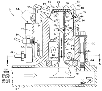
Fig. 2 shows a sectional side view of one version of the EETC
valve 10, taken along line 2-2 in Fig. 1. In this version, the EETC valve 10
is
a hydraulically actuated diaphragm valve 40. The diaphragm valve 40
reciprocates within the valve housing 22 along axis A between a first and
second state or position. The solid lines in Fig. 2 shows the valve 40 in the
first position which is associated with a valve "closed" state. Fig. 2 also
shows
the valve's second position in phantom which is associated with a valve "open"
state. In the first "closed" position, the valve 40 prevents flow of
temperature
control fluid (hereafter, "TCF") through passageway opening 42. In the second
"open" position, the valve 40 allows fluid flow through the opening 42. The .
opening 42 leads to the engine radiator (not shown). Also visible in Fig. 2 is
the electrical terminal 34 and the outlet tube 38 associated with the solenoid
20,
the fluid pressure sensor 28, and one of the mounting bolts 14.
The temperature control fluid (TCF) referred to herein is typically
known in the art as "coolant. " Coolant is a substance, ordinarily fluid, used
for
cooling any part of a reactor in which heat is generated. However, as will be
described below, the TCF not only removes heat energy from engine
components but is also employed in certain embodiments to deliver heat energy
to certain engine components. Thus, the TCF is more than merely a coolant.
Likewise, while the prior art referenced herein relates to engine cooling
systems, the invention herein employs its unique valves) in an engine
temperature control system, providing both cooling and heating functions to
engine components.
~~.996~~
WO 96/0864 PCTrCTS95111742
-13-
Turning again to Fig. 2, the valve 40 reciprocates within the
valve mechanism housing 22. The housing 22 is constructed of body 44 and
cover 4b_ held together by hand clamp pr crimp dR. The hnrlv dd inch~riPC a
__ . __ _ , ~___ __a_~___ _~ _~__ __~~r __ __~~r _... .... .._..,.> . .
..............., ..
generally horizontal dividing wall 50 which divides the body 44 into upper
compartment 52 and lower compartment 54. (It should be recognized that the
dividing wall 50 is a generally cylindrical disk in three dimensions.) The
center
of the dividing disk or wall 50 has a circular bore to allow passage of a
reciprocating valve shaft or rod therethrough, as described below. A
cylindrical
collar 56 extends vertically upward and downward from the inner edge of the
dividing wall 50, thereby coinciding with the outer circumference of the
circular
bore. The collar 56 is integral with the dividing wall 50. The lower end of
the
lower compartment S4 leads to the opening 42.
As noted above, the valve 40 reciprocates between a first
"closed" position wherein the valve 40 prevents flow of TCF through
passageway opening 42 and a second "open" position wherein the valve 40
allows fluid flow through the opening 42. When the valve 40 is "closed, " the
water pump circulates the TCF only through the engine block water jacket. If
the heater or defroster is in operation, the fluid is also circulated through
a heat
exchanger for the passenger compartment heater, typically a heater core. When
the valve 40 is "open, " most of the TCF flows through the radiator before it
is
circulated through the engine block water jacket and the heater's heat
exchanger.
Thus, in the embodiment of the invention shown in Fig. 2, the
valve 40 functions in a manner similar to the prior art wax pellet thermostat.
' 25 However, unlike the fixed temperature wax pellet thermostat, the valve 40
is
electronically controlled and thus can be opened and closed according to a
computer controlled signal tailored to specific engine operating conditions
and
ambient environmental conditions.
The diaphragm valve 40 includes upper chamber 58, diaphragm
60, plate 62, lower chamber 64, shaft or rod 66, valve member 68 and biasing
CA 02199643 2005-04-29
r
- 14-
spring 70. The diaphragm 60, plate 62 and spring 70 are disposed in the
housing body's upper compartment 52. The diaphragm 60 separates the housing
body's upper compartment 52 into the upper and lower chambers 58, 64. The
spring 70 is seated on one side against a lower surface of the plate 62 and on
S the other side against an upper surface of the housing body's dividing wall
50.
The rod 66 is also seated on one side against the lower surface of the plate
62
and extends through the housing body's upper and lower compartments 52, 54.
The diaphragm 60 is mechanically linked to the valve member 68 through the
plate 62 and the rod 66. The position of the diaphragm 60 is thus
communicated through the plate 62 and the rod 66 to the valve member 68,
thereby causing the valve member 68 to reciprocate between the first and
second
positions, shown in solid and in phantom, respectively.
The lower chamber portion of the body 44 includes air bleed
opening 72 therethrough for removing and reintroducing air into the lower
chamber 64 as the diaphragm valve 40 is moved between its first and second
positions. Radial O-ring 74 prevents the hydraulic fluid from leaking out of
passage 76.
The valve 40 also includes a gasket seal 78 around the periphery
of the opening 42 to allow the valve member 68 to close off flow through the
opening 42 when the valve 40 is in the first position. In the preferred
embodiment of the invention, the gasket seal 78 also functions as the valve
seat
for the valve member 68. The gasket seal 78 is generally square in vertical
cross-section, although other shapes are contemplated by the invention. One
preferred type of gasket seal material is Vitori , manufactured by E.I. Du
Pont
De Nemours & Co., Wilmington, DE. An O-ring 80 is disposed within the
outer circumference of the rod 66 to prevent TCF in the lower compartment 54
from leaking into the valve's lower chamber 64.
In the preferred embodiment of the invention, the diaphragm 60
possesses special characteristics to allow it to more easily withstand very
high
WO 96/0864 PCTYUS95I11742
:.'; n -,
-15-
pressures. Details of the diaphragm 60 are more fully discussed with respect
to Fig. 15.
The diaphragm valve upper chamber 58 is in fluid communication
with hydraulic fluid passageway 82 through opening 84 therebetween. The fluid
passageway 82 is in fluid communication with the outlet of the hydraulic fluid
injector 18 and the inlet of the hydraulic fluid injector 20 through the
passage
76, as best shown in Fig. 4. The fluid passageway is also in fluid
communication with the fluid pressure sensor 28 to allow the pressure in the
passageway to be monitored for controlling the valve state. Diaphragm valves
of the size suitable for installation in an engine fluid passageway can
typically
withstand pressures in the range of 200 psi ( 1378 kPa) . The diaphragm
strength
is typically the first component to fail due to excessive high pressure.
Pressure
monitoring helps to ensure that pressures do not exceed those which the valve
components can safely handle.
In the preferred embodiment of the invention, the diaphragm
includes certain features to allow it to better withstand a high pressure
environment. Fig. 15 shows a preferred diaphragm and an exploded view of
the preferred manner in which the diaphragm is mounted in the diaphragm valve
mechanism housing to achieve the best results under high pressure.
Unlike prior art diaphragm valves, such as disclosed in U.S.
Patent No. 4,484,541, which are actuated and deactuated by applying and
removing a vacuum to and from an upper chamber, the diaphragm valve 40
disclosed herein is actuated by pressurized and depressurizing the upper
chamber 58 with hydraulic fluid. A hydraulic fluid system has numerous
' 25 advantages over a vacuum actuated system including less sensitivity to
temperature extremes, and increased accuracy, durability and reliability.
In operation, the valve 40 functions as follows. When the engine
is operating and it is desired to open the valve 40, the ECU sends a control
signal to the solenoid of the hydraulic fluid injector 18 to open the
injector's
valve. Simultaneously, the ECU sends a control signal to the solenoid of the
WO 96/08640 , ~~ .. PCT/rJS95111742
-16-
hydraulic fluid injector 20 to close that injector's valve, if it is not
already '
closed. Pressurized hydraulic fluid from the fluid inlet tube 36 flows through
the fluid injector 18, the hydraulic fluid passageway 82, the opening 84 and
into
the valve upper chamber 58, where it pushes against the diaphragm 60 and plate
62. When the fluid pressure against the diaphragm 60 and plate 62 exceeds the
opposing force of the biasing spring 70, the diaphragm 60 moves downward,
thereby causing the valve member 68 to move downward. The upper chamber
58 expands as the diaphragm 60 and plate 62 moves downward. As the upper
chamber 58 fills with fluid, the pressure in the chamber rises. When the
pressure sensor 28 detects that the fluid pressure has reached a predetermined
level, it causes the ECU to start a timer which runs for a predetermined
period
of time. After that time has expired, the ECU sends a control signal to the
solenoid of the hydraulic fluid injector 18 to close the injector's valve. The
hydraulic fluid in the upper chamber 58 thus remains trapped therein.
The predetermined pressure level and time period are empirically
determined so as to allow the valve member 68 to reach its open or second
position. To avoid excessively activating the injector's solenoids, the open
injector valve should be closed as soon as the diaphragm valve 40 has reached
the desired state. Also, a diaphragm valve 40 is selected which will always
open under less pressure than exists in the hydraulic fluid system that the
inlet
fluid injector 18 is attached to. To remove air trapped in the upper chamber
58
and/or connected passageways, the ECU can be programmed to open the valve
of the outlet fluid injector 20 for a short period of time (e.g., one second).
This
is similar to the technique for bleeding air from a vehicle's hydraulic
braking
system. '
If hydraulic fluid leaks out of the upper chamber 58, the pressure
sensor 28 will immediately sense this condition. The ECU responds by again
sending a control signal to the solenoid of the hydraulic fluid injector 18 to
open
the injector's valve. When the pressure sensor 28 detects that the fluid
pressure
has again reached the predetermined level, it causes the ECU to start a timer
9V0 96/08640 pCT/US95111742
3
-17-
which runs again for a predetermined period of time. After that time has
expired, the ECU sends a control signal to the solenoid of the hydraulic fluid
injector 18 to close the injector's valve.
The process of opening the EETC valve is automatically delayed
by the ECU during engine start-up until the source of the hydraulic fluid
pressure reaches it normal operating level. In one embodiment of tine
invention
which employs engine lubrication oil as the hydraulic fluid, the delay period
is
about two or three seconds to allow for lubrication of all critical engine
components.
When it is desired to close the valve 40, the above steps are
reversed. That is, the ECU .sends a control signal to the solenoid of the
hydraulic fluid injector 18 to close the injector's valve, if it is not
already
closed. Simultaneously, the ECU sends a control signal to the solenoid of the
hydraulic fluid injector 20 to open that injector's valve. The pressurized
hydraulic fluid inside the upper chamber 58 flows out of the upper chamber 58
through the opening 84, into the hydraulic fluid passageway 82, through the
open valve of the hydraulic fluid injector 20 and into the fluid outlet tube
38.
The fluid outlet tube 38 connects to a reservoir (not shown) of hydraulic
fluid.
As the hydraulic fluid empties out of the upper chamber 58, biasing spring 70
pushes the diaphragm 60 and plate 62 upward, thereby causing the valve
member 68 to move upward until the valve 40 becomes closed. When the
pressure sensor 28 detects that the upper chamber 58 is no longer pressurized,
it causes the ECU to send a control signal to the solenoid of the hydraulic
fluid
injector 20 to close that injector's valve.
' 25 The vehicle's engine does not need to be operating to close the
valve 40. Thus, during a "hot engine off soak" (i.e., the time period
subsequent to shutting off a hot engine), the valve 40 stays open since the
hydraulic fluid remains trapped in the upper chamber 58. This function mimics
prior art cooling systems which maintain an open path to the radiator until
the
thermostat's wax pellet rehardens. After the engine has cooled down, the ECU
t ~ s:
WO 96/x8640 ' ° PG"T/USgS/11742
',
-18-
(which is powered from the vehicle's battery) causes the valve 40 to close, as
described above.
Fig. 3 shows a different sectional side view of the diaphragm
version of the EETC valve 10, taken along line 3-3 in Fig. 1. This view more
clearly shows the entire path of the TCF from a passageway leading from the
engine block water jacket, through the valve 40 and to the radiator. As noted
above, if the valve 40 is closed, the TCF circulates directly back into the
engine
block water jacket, without being diverted into the radiator.
Fig. 3 also shows the inlet hydraulic fluid injector 18 and the
fluid inlet tube 36 leading thereto, along with the insert 30 associated
therewith.
As noted above, the insert 30 is preferably a brass fitting. The passageway 82
from the outlet of the injector's valve to the upper chamber 58 is not visible
in
this view but is clearly shown in Fig. 4. The fluid connection or path between
the fluid inlet tube 36 and the injector 18 is also not visible in this view
but is
understandable with respect to Fig. 6.
Fig. 4 shows yet another sectional side view of the diaphragm
version of the EETC valve 10, taken along line 3-3 in Fig. 1. This view shows
fluid passageway 86 from the outlet of the hydraulic fluid injector 18 to the
passage 76 leading to the diaphragm upper chamber 58, and from the upper
chamber 58 to the passage 76 leading from the hydraulic fluid injector 20.
Again, the fluid connections or paths between the fluid inlet and outlet tubes
36,
38 and the respective injectors 18, 20 are also not visible in this view but
are
understandable with respect to Fig. 6.
Fig. 5 is a horizontal sectional view of the EETC valve 10 in
Figs. 1 and 2, taken along line 5-5 in Fig. 2. This view shows more of the '
internal structure of the valve parts.
Fig. 6 shows diagrammatically the preferred embodiment of how
the EETC valve 10 connects to a source of hydraulic fluid. In this embodiment
of the invention, the source of hydraulic fluid is engine lubrication oil. In
Fig.
6, a portion of engine block 88 is cut away to show engine lubrication oil
pump
W~ 96/8640 ~.,~;,,~~ ~'~;Tl'~TS~~/ll'T42
i
-19-
90 and engine lubrication oil reservoir 92 in oil pan 94. As is well known in
the art, outlet 96 of the oil pump 90 feeds oil to practically all of the
engine
moving parts under pump pressure through distributing headers (not shown).
To provide a source of pressurized hydraulic fluid to the inlet fluid injector
18,
the fluid inlet tube 36 is connected to the oil pump outlet 96. An optional
replaceable filter 98 may be placed in the pressurized oil line to ensure that
the
oil flowing to the valve 10 does not clog the injectors. To provide a return
path
for the hydraulic fluid exiting from the outlet fluid injector 20, the fluid
outlet
tube 38 is connected to the oil reservoir 92 in the oil pan 94.
Figs. 7 and 8 show another preferred form of an EETC valve 100
which simultaneously controls the flow of TCF to plural parts of an engine. In
a first embodiment, the EETC valve 100 controls fluid flow to the radiator and
the oil pan. When the EETC valve 100 is in a first position, flow to the
radiator is blocked and flow to the oil pan is permitted. When the EETC valve
100 is in a second position, flow to the radiator is permitted and flow to the
oil
pan is blocked. Fig. 7 shows the EETC valve 100 in the first position, whereas
Fig. 8 shows the valve in the second position.
In a second embodiment, the EETC valve 100 controls fluid flow
to the radiator, oil pan and a portion of the engine block water jacket. In
the
depicted embodiment, that portion of the water jacket comprises the portion
around the intake manifold. When the EETC valve 100 is in a first position,
flow to the radiator is blocked and flow to the oil pan and the intake
manifold
is permitted. When the EETC valve 100 is in a second position, flow to the
radiator is permitted, flow to the oil pan is blocked, and flow to the intake
manifold is either restricted or blocked. Again, Fig. 7 shows the EETC valve
100 in the first position, whereas Fig. 8 shows the valve in the second
position.
The EETC valve 100 employs a diaphragm valve 102. The
sectional view in Fig. 7 is slightly different than the section taken of EETC
valve 10 through line 2-2 in Fig. 1 so as to show the TCF passage through the
EETC valve 100. It should be noted that a top plan view of the EETC valve
,>
WO 96/08640 ~ ~ w - Pt:TYUS9S/1I742
-20-
100 will appear identical to EETC valve 10 shown in Fig. 1. Furthermore, the "
valve parts and housing of EETC valve 100 differ only slightly from the EETC
valve 10. One difference between EETC valve 10 and EETC valve 100 lies in
the shape of the housing body's dividing wall and collar attached thereto. In
the
embodiment of the invention shown in Fig. 7, dividing wall 104 has a unique
shape to allow it to accept a unique stationary rod seal 106. The seal 106
performs a function similar to the O-ring 80 shown in Fig. 2. That is, the
seal
106 prevents TCF in the valve's lower compartment 108 from leaking into the
valve's lower chamber 142. The EETC valve 100 is similar to the EETC valve
10 in that its housing 112 includes a body 114 and a cover 116, held together
by band clamp or crimp 118.
The dividing wall 104 in Fig. 7 is defined by three integrally
formed portions, a downwardly tapered portion 120 attached at one end to a
sidewall of housing 112, a generally vertical portion 122 attached at one end
to
the other end of the tapered portion 120, and a generally horizontal portion
124
attached at one end to the other end of the generally vertical portion 122.
The
center of the dividing wall 104 has a circular bore to allow passage of
reciprocating valve rod 126 therethrough, in the same manner as the valve rod
in EETC valve 10. Thus, the generally horizontal portion 124 does not extend
completely across the radius of the housing 112. A cylindrical collar 128
extends vertically upward from the other end of the horizontal portion 124
(i.e.,
from the inner edge of the dividing wall 104), thereby coinciding with the
outer
circumference of the circular bore. Unlike the collar 56 in diaphragm valve
40,
the collar 128 does not extend downward from the dividing wall 104. Instead,
the dividing wall 104 includes an integrally formed extension flange 130 which
extends perpendicularly downward by a short distance from a center region of
the horizontal portion 124. The unique stationary rod seal 106 is attached to
a
lower surface of the dividing wall 104 as best shown in Fig. 13A.
Fig. 13A shows an enlarged view of the circled dashed region in
Fig. 7 associated with the stationary rod seal 106. Reciprocating valve rod
126
WO 96/08640 PCT/a1S95/11742
T <
-21 -
moves along axis A adjacent to the inner sidewall of the dividing wall's
horizontal portion 124. The extension flange 130 includes a curved outer wall
surface 132 and a generally planar inner wall surface 134. The extension
flange
130 extends downward from the horizontal portion by a distance of about dl.
A cylindrical seal 136 having a generally rectangular vertical cross-section
is fit
into the space between the extension flange's inner wall surface 134 and the
outer circumferential wall of the rod 126 (or the outer circumferential wall
of
the dividing wall's bore, if the rod 126 is not yet inserted into place). The
seal
136 has a vertical width slightly less than dl so that the seal I36 lies
approximately flush with a horizontal plane formed by the lower surface of the
extension flange 130. The seal 136 also has a circular impression therein for
accepting O-ring 138. Retention cup 140 is attached to the lower surface of
the
extension flange 130 and the seal 136. The outer edge of the cup 140 wraps
around the curved outer wall surface 132 of the extension flange I30.
One suitable material for the retention cup 140 is a brass cup
crimped over the curved outer wall surface 132. A suitable material for the
seal
136 is a standard POLYPAK~ retention seal manufactured by Parker-Hannifin
Corp., Cleveland, OH. A suitable rod 126 will have an outer diameter of about
3/8 inch (0.95 cm). A stationary rod seal 106 constructed with those materials
will withstand TCF pressures of at least 50 psi (345 kPa).
The stationary rod seal 106 inhibits debris which becomes lodged
on the lower portion of the rod 126 from traveling up into the valve's lower
chamber 142 when the rod 126 moves from the second position shown in Fig.
8 to the first position shown in Fig. 7. The stationary rod seal 106
effectively
' 25 acts as a wiper, dislodging any such debris from the rod 126 and
depositing in
the valve's lower compartment 108 where it can be carried away by the TCF.
The dividing wall -104/stationary rod seal 106 feature in EETC
valve 100 can replace the dividing wall/O-ring sealing structure in EETC valve
10.
~~;,..,. i .4
f; s......;: ,~
WO 96/08640 PCT/US95/i1742
-22-
Turning again to Fig. 7, the diaphragm valve 102 includes a
reinforced gasket seal 144. The details of the gasket seal 144 are shown more
clearly in Fig. 13B. The gasket seal 144 also functions as the valve seat for
valve member 146.
Fig. 13B shows an enlarged view of the circled dashed region in
Fig. 7 associated with the gasket seal 144. The gasket seal 144 provides two
functions. First, it functions as a sealing seat for the valve member 146.
Second, it prevents the TCF from flowing into the valve's lower compartment
108 when the EETC valve 100 is in the first position.
The gasket seal 144 includes an elastomer material 148 having a
cut-out 150. A washer 152, preferably of stainless steel, is snapped into the
cut-out 150. The washer 152 limits the travel of the valve member 146 by
strengthening and supporting the gasket seal 144, thereby increasing the
integrity of the seal 144. If the cut-out 150 and washer 152 were not present,
the valve member 146 would be more prone to push through the elastomer
material 148 under high pressure conditions. To inhibit this from occurring,
the
inner diameter of the washer 152 is dimensioned to be smaller than the outer
diameter of the bottom of the valve member 146.
The gasket seal 144 is pressed into a cut-out 154 in a wall of
TCF passageway 156, although it may also be located in a cut-out of a wall of
the valve's lower compartment 108. The cut-out 154 and the washer's 'cut-out
150 are dimensioned so that an outer diameter portion of the washer 152
recesses in the wall. This arrangement tightly traps the washer 152 into
position.
As noted above, the first embodiment of the EETC valve 100
controls fluid flow to the radiator and the oil pan. This is accomplished by
including an opening 158 in the TCF passageway 156 leading to an additional
TCF passageway 160. The passageway opening 158 is positioned within the
passageway 156 so that when the valve member 146 is in the first position (as
shown in Fig. 7), the valve member 146 does not block the opening 158,
WO 96108640 pC7C/US95111742
a
r , r ~~_. ~.: .~.
- 23 -
thereby allowing flow of a portion of the fluid therethrough. When the valve
member 146 is in the second position (as shown in Fig. 8), the valve member
146 becomes seated against the opening 158, thereby closing the opening 158,
and thus preventing flow of any of the fluid therethrough.
The diaphragm valve 102 does not need to be modified to provide
the additional control function associated with the fluid flow to the oil pan.
It
is only necessary to position the opening 158 so that the valve member 146
seats
over it at the end of its stroke, as shown in Fig. 8.
Fig. 15 shows the preferred diaphragm 102 exploded from the
housing body 114 and valve cover 116. The diaphragm 102 is foamed from a
. flexible material which moves between the first position shown in Fig. 7 and
the
second position shown in Fig. 8 as hydraulic fluid fills into and empties from
the diaphragm valve's upper chamber. The diaphragm 102 includes an
integrally molded O-ring type flange 110 which extends downward from the
outer circumference and seats into groove 162 formed in the upper edge of the
body 114. The diaphragm also includes an integrally molded bead 164 on the
top side of the flange 110. The preferred material for the diaphragm 102 is an
elastomer 166, covered with fabric 168 on its lower surface. One suitable
combination of elastomer and fabric is Vitori and NomeX , both manufactured
by E.I. Du Pont De Nemours & Co., Wilmington, DE. This type of diaphragm
is designed by RPP Corporation, Lawrence, MA.
The size of the diaphragm 102 is determined by the dimensions
of the EETC valve 100. In one embodiment of the invention wherein the EETC
valve 100 is sized to replace a prior art wax pellet or bimetallic coil type
thermostat, a suitable diaphragm 102 will have the following dimensions:
1. end-to-end diameter of about 1.87 inches (4.75 cm);
2. top-to-bottom height of about .55 inches; (1.397 cm)
2. flange diameter and height of about .094 inches (0.239 cm);
and
3. bead 164 radius of about .015 inches (0.0381 cm).
a1 i :; ,f ~.a Z..~
. . ° fq ~, ~. .W~;
WO 96/08640 PCT/LTS95/11742
-24-
A diaphragm 102 sized as such will fit into a cylinder bore having a diameter
of about 1.43 inches (3.632 cm) and will accept an upper plate of a piston rod
having a diameter of about 1.18 inches (2.997 cm).
Since Fig. 15 shows the preferred embodiment of the housing
bodyldiaphragm/valve cover subassembly, it should be understood that the
equivalent subassembly in the EETC valve 10 also preferably employs this
embodiment. The diaphragm in the EETC valve 10 has an integrally molded
O-ring type flange which extends upward from the outer circumference and
seats into a groove formed in the lower edge of the valve cover. The
diaphragm in the EETC valve 10 is also preferably an elastomer, covered with
fabric on its lower surface. The diaphragm in the EETC valve 10 does not
include an integrally molded bead on an opposite side of the flange.
Accordingly, it is easier and cheaper to manufacture.
The particular features of the diaphragm 102 and the manner in
which it is assembled between the housing body 114 and valve cover 116 allows
the diaphragm 102 to withstand larger pressures than the diaphragm of the
EETC valve 10.
Fig. 14 diagrammatically shows a temperature control system of
an internal combustion engine employing the mufti-function EETC valve 100 of
Figs. 7 and 8, including the first and second embodiments of fluid flow
provided by the dual action diaphragm valve 102. The fluid paths to and from
the automobile heater are not shown in this simplified diagram.
When the EETC valve 100 is employed in its first embodiment
to control fluid flow only to the radiator and the oil pan, the system shown
in
Fig. 14 function as follows.
When the diaphragm valve 102 is in the second position shown
in Fig. 8 (i.e., open to TCF flowing to the radiator, closed to TCF flowing to
the oil pan), the TCF enters a TCF jacket 200 formed in a cylinder block.
From there, it is supplied to TCF jackets 202 and 204 formed respectively in
a cylinder head and an intake manifold. The engine TCF leaving the jackets
'VV~D 9x/08640 PCTIUS95/11742
.. . ~ X~ .r.
-25-
' 200, 202 and 204 flows through the valve 102 and is introduced to radiator
206
through radiator inlet passage 208. The TCF which enters the radiator 206 is
cooled during its passage therethrough by air flow from cooling fan 210
located
at the rear side of the radiator 206. The cooled TCF is supplied to a TCF
pump 212 (e.g., a water pump) through the radiator outlet passage 214. The
TCF supplied to the pump 212 is again circulated to the jackets 200, 202 and
204.
When the diaphragm valve 102 is in the first position shown in
Fig. 7 (i.e., closed to TCF flowing to the radiator, open to TCF flowing to
the
oil pan), the TCF which enters the TCF jacket 200 is supplied to the TCF
jackets 202 and 204. The engine TCF leaving the jackets 200 and 202 bypasses
the radiator 206 through bypass passage 216 and is delivered directly to the
pump 212 for recirculation. Since the passageway 160 is now open to fluid
flow, a portion of the TCF flows therethrough and into heat exchanger 218 in
the oil pan 94. The heat exchanger 218 comprises a U-shaped heat conductive
tube 220 which allows heat from the TCF to pass into the oil in the oil pan
94.
Other tubing shapes are also suitable. The TCF exiting the heat exchanger 218
flows back into the pump 212 for recirculation.
In cold temperature environments, or when an engine is first
warmed up, the engine lubrication oil should be heated to its normal operating
temperature as rapidly as possible, and maintained it .at that temperature. In
prior art engine cooling systems, engine coolant is not employed to assist in
this
goal. To the contrary, prior art systems work against this goal by immediately
circulating coolant through the jacket and removing heat from the engine
block,
and thus from the engine oil.
This invention helps to achieve that goal by circulating a portion
of the TCF through the oil pan 94. Since the diaphragm valve 102 is likely to
be in the Fig. 7 first position in cold temperature environments, or when the
engine is first warmed up, the oil in the oil pan 94 will receive warm or hot
TCF when it needs it the most. The heat energy transferred from the warm or
WO 96f0S640 ~ - PGT/US95/11742
;~ .,;
-26-
hot TCF into the oil allows the oil to more quickly reach its ideal operating
temperature. In effect, the TCF diverted to the oil pan 94 recaptures some of
the parasitic engine heat loss caused by circulation of the TCF.
Furthermore, the inventive system described herein allows the
engine oil to capture some of the heat energy in the TCF after the engine is
turned off. In contrast, the heat energy in the coolant of prior art cooling
systems is wasted by being passed into the environment. Since the valve 102
will always be in the first position after engine cooldown, heat energy can
pass
by convection through the passageway 160 and into the oil pan 94. If the
ambient air temperature is very cold, the valve 102 may even remain in the
first
position during and after engine operation. Thus, convective heating of the
engine oil will continue after the engine is turned off. The mass of hot TCF
has
the potential to keep the engine oil warm for hours after engine shut-off.
As noted above, the EETC valve 100 operates in a second
embodiment wherein it controls fluid flow through the radiator, oil pan and a
portion of the engine block water jacket (e.g., the portion around the intake
manifold). When the EETC valve 100 is in a first position, flow to the
radiator
is blocked and flow through the oil pan and through intake manifold is
permitted. When the EETC valve 100 is in a second position, flow to the
radiator is permitted, flow to the oil pan is blocked, and flow through the
intake
manifold is either restricted or blocked.
Operation of the second embodiment of the EETC valve 100 is
best understood with respect to Figs. 8 and 14. The valve's hydraulic fluid
passageway 170 includes opening 172 leading to fluid outlet tube 174 through
housing insert 176, preferably a brass fitting. The outlet tube 174 is
connected
to an intake manifold flow control valve. This valve is not shown in Fig. 8,
but
is labelled in Fig. 14 as valve 300. The valve 300 controls the flow of fluid
through the intake manifold jacket 204 which surrounds the intake manifold
(not
shown) . For the purposes herein, the valve 300 can be any valve which is
moved from a first position to a second position by hydraulic fluid pressure
W~ 96/08640 ~ PCTIUS95/11742
a ~'
-27-
applied to a valve chamber, wherein the first position is associated with
unrestricted fluid flow through an associated passageway and the second
position
is associated with either restricted or blocked flow through the passageway.
One example of a valve 300 suitable for this purpose is described in Figs. 24-
30
of this disclosure. However, the valve 300 can comprise any type of
hydraulically fluid actuated valve such as a piston valve, diaphragm valve or
the
like.
When it is desired to move the diaphragm valve 102 into the
second position shown in Fig. 8, pressurized hydraulic fluid flows through the
passageway 170 into upper chamber 178. Simultaneously, a portion of the
hydraulic fluid flows through the opening 172, into the fluid outlet tube 174
and
into the chamber (not shown) of the intake manifold flow control valve 300.
The pressurized fluid in this chamber causes the valve 300 to move from the
first position (unrestricted flow) to the second position (restricted or
blocked
flow).
When it is desired to move the diaphragm valve 102 back into the
first position shown in Fig. 7, the hydraulic fluid in the upper chamber 178
flows out through an outlet hydraulic fluid injector in the same manner as
described with respect to Figs. 2-5. Likewise, the hydraulic fluid in the
chamber of the valve 300 flows back into the EETC valve 100 and out through
this outlet hydraulic fluid injector. In this manner, the state of the EETC
valve
100 determines the state of the valve 300.
The purpose of this control scheme is to reduce the amount of
heat energy flowing through the intake manifold when the engine is hot. In a
typical internal combustion engine, tine intake manifold has an ideal
temperature
of about 120 degrees Fahrenheit. In such engines, there is no significant
advantage in heating the intake manifold to temperatures higher than about 130
degrees Fahrenheit. In fact, extremely hot intake manifold temperatures reduce
combustion efficiency. The volume of air expands as it is heated. As the air
volume expands, the number of oxygen molecules per unit volume decreases.
'4 ~ y, t ,w
.1y ~~.; ; t ''~'
WO 96/08640 Y'' ~ ~~ PCdYUS95111742
-28-
Since combustion requires oxygen, reducing the amount of oxygen molecules '
in a given volume decreases combustion efficiency. Prior art cooling jackets
typically deliver coolant through the intake manifold at alI times. When an
engine is running hot, the coolant temperature is typically in a range from
about
160 (71.1 °C) to about 200 (93.3 °C) degrees Fahrenheit. Thus,
the coolant may
be significantly hotter than the ideal temperature of the intake manifold.
Nevertheless, the prior art cooling system will continue to deliver hot
coolant
through the intake manifold, thereby maintaining the intake manifold
temperature in an excessively high range.
The second embodiment of the invention described herein
employs the EETC valve 100 to restrict or block the flow of TCF through the
intake manifold, thereby avoiding the unwanted condition described above.
When the EETC valve 100 is in the first position shown in Fig. 7, it is likely
that the temperature of the TCF is below that which would cause the intake
manifold to exceed its ideal operating temperature. Thus, when the EETC
valve 100 is in the first position, flow of TCF through the intake manifold is
permitted.
The intake manifold flow control valve scheme can also be
employed with the EETC valve 10 shown in Figs. 2-5. This scheme functions
with or without the modification to the temperature control fluid passageway
12
for diverting the fluid to the oil pan. In Fig. 14, the valve 300 is shown at
the
end of the intake manifold jacket 204, thereby "dead heading" the flow of
fluid
through the jacket 204. "Dead heading" is used herein to describe the state
whereby the flow of fluid is blocked but the fluid still remains in the water
jacket passage due to the continuous pumping of fluid by the engine's water
pump. "Restricting" is used herein to describe the state whereby the flow of
fluid is partially 'blocked but a portion of the fluid still flows in the
water jacket
passage due to the continuous pumping of fluid by the engine's water pump.
Since heat energy is primarily transferred to and from the engine block by the
flow of fluid, dead heading the flow will have almost the same effect as
shutting
CVO 96/0S54'0 PCT/L1S95/11742
r:
-29-
' off the flow. However, a minimum amount of convective fluid heat flow will
still occur between the intake manifold jacket 204 and the cylinder head and
block jackets 200 and 202 in this configuration. Alternatively, the valve 300
can be placed in the passageway leading to the beginning of the intake
manifold
jacket 204 (shown in phantom), thereby preventing both fluid flow through the
intake manifold jacket 204 and convective fluid heat flow between the jacket
204 and the jackets 200 and 202.
The configuration in Figs. 7 and 8 wherein the EETC valve 100
controls fluid flow to the radiator, oil pan and a portion of the engine block
water jacket (e.g., the portion around the intake manifold) produces a highly
effective engine temperature control system in a wide range of ambient
temperature conditions, as well as during engine warm up. In cold temperature
environments and during warm up, the EETC valve 100 allows flow of the TCF
to the oil pan and the intake manifold, thereby causing the engine oil and
intake
manifold to more rapidly reach their ideal operating temperatures. Once the
engine is sufficiently warmed up, or when the engine is operating in very hot
ambient air temperatures, the EETC valve 100 shuts off flow of the TCF to
both the oil pan and the intake manifold since neither the oil, nor the intake
manifold need additional heat energy under either of those conditions.
The EETC valve 100 can also control the flow of the TCF to
portions of the engine block water jacket other than the portion around the
intake manifold. The valve 300 shown in Fig. 14 can alternatively be placed
to block or restrict flow through portions of the cylinder block jacket 200 or
the
cylinder head jacket 202. In another embodiment, a plurality of water jacket
' 25 blocking/restricting valves can be snmultaneously controlled from the
hydraulic
fluid system of the diaphragm valve 102. Fig. 14 shows one such additional
1
valve 400 in phantom at the end of the cylinder head jacket 402.
The EETC valve 100 can also be employed to address a design
compromise inherent in prior art engine cooling systems employing prior art
thermostats. Prior art Figs. 31 and 32 show a 'simplified diagrammatical
.. ;~.
:.
WO 96/0864~ ' PCT/US95/11742
a
-30-
representation of coolant circulation flow paths through such an engine. The '
coolant temperature is represented by stippling densities, hot coolant having
the
greatest density and cold coolant having the smallest density. Fig. 31 shows
that when thermostat 1200 is closed, the coolant that exits water jacket 1202
flows through orifice 1204, into the intake side of water pump 1206, and then
back to the water jacket 1202. Thus, the coolant circulates entirely within
the
engine water jacket 1202, avoiding radiator 1208. Fig. 32 shows that when the
thermostat 1200 is open, all of the coolant circulates through the radiator
1208,
into the intake side of the water pump 1206, and then back to the water jacket
1202.
Fig. 32 is an idealized diagram of coolant flow. Since fluid takes
the path of least resistance, most of the coolant will flow through the larger
opening associated with the thermostat 1200, as opposed to the more
restrictive
orifice 1204. However, a small amount of coolant still passes through the
orifice 1204 and into the intake side of the water pump 1206, as shown in
prior
art Fig. 33. Since this small amount of coolant is not cooled by the radiator
1208, it raises the overall temperature of the coolant reentering the water
jacket
to a level higher than is desired.
To minimize this problem, the opening associated with the
thermostat 1200 is made as large as possible and the orifice 1204 is made as
small as possible. However, if the orifice 1204 is made too small, circulation
through the water jacket 1202 will be severely restricted when the thermostat
1200 is closed. This may potentially cause premature overheating of portions
of the engine block and will reduce the amount of heat energy available for
the
heater and intake manifold during engine start-up and in cold temperature
environments. If the orifice 1204 is made too large, the percentage of coolant
flowing therethrough will be large when the thermostat 1200 is open.
Accordingly, the average temperature of the coolant returning to the water
jacket 1202 will be too hot to properly cool the engine.
WO 96I0~640 ~~ ,~j~~ . PCT/US95/11742
-31-
Thus, prior art engine cooling systems must always attempt to
strike the proper balance between extremes when sizing the orifice 1204,
thereby resulting in a compromised, but never idealized, size. In an idealized
system, the orifice 1204 is open and large when the thermostat 1200 is closed,
S and is closed when the thermostat 8200 is open.
Fig. 34 shows how the EETC valve 100 can be employed to
create this idealized system. Fig. 34 is similar to Figs. 7 and 8, except that
the
opening 158 shown in Figs. 7 and 8 is an orifice 1210 and this orifice 1210 is
the only fluid flow path for the TCF when the EETC valve 100 is in the first
position shown in Fig. 7. That is, there is no alternative path to the water
pump when the EETC valve 100 is in the first position. This is ira contrast to
the system in Fig. 7 wherein a portion of the TCF flows through the opening
158 and into the passageway 160, and the remaining portion of the TCF flows
to the water pump.
Since the orifice 1204 shown in Figs. 31-33 merely functions as
a path for coolant to return to the water pump 1206 for recirculation through
the
water jacket 1202, the system in Fig. 34 takes advantage of this already
existing
return path (shown in Fig. 18) to achieve the same function.
The orifice 1210 can be sized as large as allowed by the valve
member 146, and thus need not be restricted in size by the constraints
described
above with respect to the prior art engine cooling systems. The TCF flowing
through the orifice 1210 travels through the passageway 160 and follows the
same path as shown in Fig. 18. When the EETC valve 100 in the configuration
in Fig. 34 is in the second position (not shown, but similar to Fig. 8), no
TCF
can flow through the orifice 1210, thereby achieving the idealized "no flow"
state unattainable in the prior art system described above.
The EETC valve 100 can also be employed in an anticipatory
mode to address one problem in prior art engine cooling systems, specifically,
the problem of sudden engine block temperature peaks caused when a
turbocharger or supercharger is activated. These sudden peaks, in turn, may
wo 9siossao
rcrrus~snma2 O
-32-
cause a rapid rise in coolant temperature and engine oil temperature to levels
which exceed the ideal range. Since prior art cooling systems typically cannot
shut off flow of coolant to the intake manifold, the rise in engine block
temperature causes even more unnecessary heat energy to flow around the
already overheated intake manifold. Furthermore, if the engine is still
warming
up, the prior art wax pellet type thermostat might not even be open. The
thermostat might also be closed even if the coolant temperature has reached
the
range in which it should open, due to hysteresis associated with melting of
the
wax.
The invention herein can employ the EETC valve 100 to lessen
the temperature rise effects of the turbocharger or supercharger. When the
turbocharger or supercharger is activated, a signal can be immediately
delivered
to the EETC valve 100 to cause it to move into its second position, as shown
in Fig. 8, if it is already not in that position. This will stop the flow of
TCF
to the engine oil and through the intake manifold, in anticipation of a rapid
temperature rise in the oil and the intake manifold due to the action of the
turbocharger or supercharger. Likewise, the flow o~TCF through the radiator
will lessen any peaking of the engine block temperature. A short time after
the
turbocharger or supercharger is deactivated, the EETC valve can then be
returned to the state dictated by the ECU.
Although the preferred embodiment of the invention employs a
diaphragm valve in valves 10 and 100, other types of hydraulically activated
chamber-type valves can be employed in place of the diaphragm valve. One
particularly suitable type of valve is a piston valve having a piston head
which
reciprocates within the bore of a piston housing, wherein the piston head
includes a piston shaft and a cup.
Figs. 9 and 10 disclose one embodiment of a piston valve and
Figs. 11 and 12 disclose another embodiment of a piston valve. Both types of
valves provide a fluid flow passageway through at least a portion of the
housing
when the valve is open and block off the fluid flow passageway through that
WO 96/08640 ~ 1'CTIUS95/11742
-33-
portion of the housing when the valve is closed. Both types of valves employ
the outer circumferential wall of their piston shafts to block a fluid
passageway
opening through the housing, thereby preventing fluid flow through any portion
of the housing. The valves allow flow of fluid through the portion of the
housing by moving the outer circumferential wall of their piston shafts wall
away from the opening. The valve embodiment in Figs. 11 and I2 is a flow-
through type of valve. That is, when the valve is open, the fluid controlled
by
the valve flows through the interior of the piston head. In contrast, in the
embodiment in Figs. 9 and 10, the fluid does not flow through the piston head.
In both of the piston valve embodiments, the piston head is
moved from the closed to the open position by the force of hydraulic fluid
pressure against a rear surface of the cup, and is moved back to the closed
position by the force of a biasing spring, in a manner similar in principle to
movement of the diaphragm valves in valves 10 and 100. The hydraulic fluid
enters and leaves the piston valve through a pair of hydraulic fluid injectors
in
the same manner as in the valves 10 and 100.
Fig. 9 shows a sectional side view of EETC valve 500 and Fig.
10 shows a right end view of the EETC valve 500 in Fig. 9. The solid lines
in Fig. 9 shows the EETC valve 500 in its first position which is associated
with a valve "closed" state. Fig. 9 also shows the valve's second position in
phantom which is associated with a valve "open" state. For clarity, Figs. 9
and
10 are described together.
The EETC valve 500 includes valve mechanism casing or housing
502, piston head 504, an inlet hydraulic fluid injector 18 and an outlet
hydraulic
' 25 fluid injector 20. Only the inlet hydraulic fluid injector 18 is visible
in Fig. 9,
whereas both injectors 18, 20 are visible in Fig. 10. Injector 18 is connected
to fluid inlet tube 36 and injector 20 is connected to fluid outlet tube 38,
in the
same manner as the valves 10 and 100.
The housing 502 is a generally cylindrical solid structure having
a bore 506 therethrough. The housing 502 is bolted closed at one end 508 by
~ .,
v7.
a~
WO 96/08640 , ~ PCTIUS95I11742
4
-34-
cover 510 and open at the other end 512. The housing 502 is defined by five
main parts, the cover 510, a first cylindrical portion 514 having an inner
diameter of about d1, a second cylindrical portion 516 having an inner
diameter '
of about da and two barrels 518, 520 extending from the housing 502, each
barrel housing one of the fluid injectors 18, 20. Barrel 518 and injector 18
are
visible in Fig. 9. Only the barrel 518 is visible in Fig. 9, whereas both
barrels
518, 520 are visible in Fig. 10. The diameter da is larger than dl.
The housing 502 also includes two openings therethrough. A first
opening 522 located in a mid-region of the first cylindrical portion 514
allows
temperature control fluid (TCF) from passageway 524 to pass therethrough
when the first opening 522 is not obstructed by the piston head 504. A second
opening (not shown) allows hydraulic fluid to flow into and out of a chamber
526 within the housing's second cylindrical portion 516, to and from the pair
of fluid injectors 18, 20. Fluid pressure sensor 550 is in communication with
the chamber 526. The sensor 550 is visible in Fig. 10 but is not visible in
Fig.
9. This sensor 550 performs the same function as the fluid pressure sensor 28
in the EETC valve 10.
The piston head 504 is a unitary solid structure defined by two
main parts, a piston shaft 528 and a piston cup 530 connected to one end of
the
shaft 528. The other end of the shaft 528 is closed. The piston cup 530 and
the left hand portion of the piston shaft 528 reciprocate within the 'second
cylindrical portion 516 of the housing 502. The piston shaft 528 is a
preselected length which allows its outer circumferential wall to block the
first
opening 522 when the piston head 504 is in the first position and allows its
outer circumferential wall to move completely away from the first opening 522
when the piston head 504 is in the second position. The piston shaft 528 has
an outer diameter d3 which is slightly less than dl, thereby allowing the
shaft '
528 to fit tightly within the bore's first cylindrical portion 514. Likewise
the
piston cup 530 has an outer diameter d, which is slightly less than d2,
thereby
allowing the cup 530 to fit tightly within the bore's second cylindrical
portion
CA 02199643 2005-04-29
-35-
516. The cup 530 has a rear surface 532 which faces the piston shaft 528. The
cup includes grooves 534 around its outer circumferential surface for seating
piston O-rings 536 therein. Likewise, the inner circumferential surface of the
bore's first cylindrical portion 514 includes grooves 538 around its
circumference for seating O-rings 540 therein. The cup 530 also includes a
cup-shaped insert 538 for holding one end of biasing spring 542 therein.
The EETC valve 500 is biased in the closed position by the
biasing spring 542 which is mounted at the one end to an inner surface of the
cup's insert 538A and at the other end to an inner surface of the cover 510.
To
hold the other end of the spring 542 in place, the cover 510 includes knob 544
which extends perpendicularly into the bore 506 from the center of its inner
surface, the other spring end being seated around the knob 544.
To move the EETC valve 500 from its first position to its second
position, the valve associated with the fluid injector 18 is opened in
response to
a control signal from an ECU (not shown). Simultaneously, the valve
associated with the fluid injector 20 is closed, if it is not already closed.
Pressurized hydraulic fluid from the fluid inlet tube 36 flows through the
injector 18 and into the chamber 526, where it pushes against the piston cup's
rear surface 532. When the fluid pressure against the cup's rear surface 532
exceeds the opposing force of the biasing spring 542, the piston head 504
moves
to the left until it reaches the second position shown in phantom, thereby
causing the piston shaft 528 to move away from the first opening 522. The
TCF in the passageway 524 can now flow through the right hand portion of the
housing 502 and into the radiator. A pressure sensor (not shown) and the ECU
(not shown) cooperate in the same manner as described with respect to the
EETC valve 10 to determine when to close the valve of the hydraulic fluid
injector 20, thereby trapping the hydraulic fluid in the chamber 526. Thus,
the
piston shaft 528 will remain in the second position as long as the fluid
injector
valves remain closed. The O-rings 536 and 540 prevent the hydraulic fluid in
the chamber 526 from leaking out into other parts of the housing 502.
R'O 96/08640 , PC~r~US95/117~2
-36-
Likewise, the O-rings 540 prevent the TCF from leaking into other parts of the
housing 502.
When it is desired to close the EETC valve 500, those steps are
reversed. That is, the ECU sends a control signal to the solenoid of the
hydraulic fluid injector 18 to close the injector's valve, if it is not
already
closed. Simultaneously, the ECU sends a control signal to the solenoid of the
hydraulic fluid injector 20 to open that injector's valve. The pressurized
hydraulic fluid inside the chamber 526 flows out through the housing's second
opening (not shown), through the open valve of the hydraulic fluid injector 20
and into the fluid outlet tube 38. As the hydraulic fluid empties out of the
chamber 526, the biasing spring 542 pushes the piston head to the right and
into
the first position, thereby causing the piston shaft 528 to block the first
opening
522 and shut off fluid flow through the EETC valve 500. When the pressure
sensor (not shown) detects that the chamber 526 is no longer pressurized, it
causes the ECU to send a control signal to the solenoid of the hydraulic fluid
injector 20 to close that injector's valve.
Figs. 11 and 12 show a flow-through version of a piston valve
suitable for use as an EETC valve. Fig. 11 shows a sectional side view of
EETC valve 600 and Fig. 12 shows a right end view of the EETC valve 600 in
Fig. 11. The solid lines in Fig. 11 shows the EETC valve 600 in its first
position which is associated with a valve "closed" state. Fig. 11 also shows
the
valve's second position in phantom which is associated with a valve "open"
state. For clarity, Figs. 11 and 12 are described together.
The EETC valve 600 includes valve mechanism casing or
housing 602, piston head 604, an inlet hydraulic fluid injector 18 and an
outlet
hydraulic fluid injector 20. Only the inlet hydraulic fluid injector 18 is
visible
in Fig. 11, whereas both injectors 18, 20 are visible in Fig. 12. Injector 18
is
connected to fluid inlet tube 36 and injector 20 is connected to fluid outlet
tube
38, in the same manner as the valves 10 and 100.
'WO 96/08640 ~ . PG"TfUS95111742
-37-
The housing 602 is a generally cylindrical solid structure having
a bore 606 therethrough. The housing 602 is closed at one end 608 and open
at the other end 612. The housing 602 is defined by five main parts, including
three cylindrical portions and two barrels. The three cylindrical portions
are,
S from left to right, a first cylindrical portion 614 having an inner diameter
of
about dl, a second cylindrical portion 616 having an inner diameter of about
da
and a third cylindrical portion 617 having an inner diameter of about d3. The
diameter da is larger than dl and the diameter d3 is about the same as dl. The
first cylindrical portion 614 is closed at the left end (which corresponds to
the
closed housing end 608) and open at the right end. The second and third
cylindrical port. ions 616 and 617 are open at both ends. The right end of the
third cylindrical portion 617 corresponds to the open housing end 612. The
third cylindrical portion 617 is a separate structural piece and is bolted to
the
second cylindrical portion 616 by an integral circular flange 646. The left
end
of the third cylindrical portion 617 extends slightly into the right end of
the
second cylindrical portion 616. Two barrels 618, 620 extend from the housing
602, each barrel housing one of the fluid injectors 18, 20. Barrel 618 and
injector 18 are visible in Fig. 9. Only the barrel 618 is visible in Fig. 11,
whereas both barrels 618, 620 are visible in Fig. 12.
The housing 602 also includes two openings therethrough. A first
opening 622 located near the left end of the first cylindrical portion 614
allows
temperature control fluid (TCF) from passageway 624 to pass therethrough
when the first opening 622 is not obstructed by the piston head 604. A second
opening (not shown) allows hydraulic fluid to flow into and out of a chamber
' 25 626 within the housing's second cylindrical portion 616, to and from the
pair
of fluid injectors 18, 20. Fluid pressure sensor 650 is in communication with
the chamber 626. The sensor 650 is visible in Fig. 12 but is not visible in
Fig.
10. This sensor 650 performs the same function as the fluid pressure sensor 28
in the EETC valve 10.
P~'IU~95/i 1?42
WO 96/08640
Y
-38-
The piston head 604 is a unitary solid structure defined by two '
main parts, a hollow piston shaft 628 and a piston cup 630 connected to one
end
w
of the shaft 628. Unlike the other end of the shaft 528 in the piston head
504,
the other end of the shaft 628 (i.e., the left end) is open. Also, a center
region
of the piston cup 630 is hollow. The piston cup 630 and the right hand portion
of the piston shaft 628 reciprocate within the second cylindrical portion 616
of
the housing 602. The piston shaft 628 is a preselected length which allows its
outer circumferential wall to block the first opening 622 when the piston head
604 is in the first position and allows its outer circumferential wall to move
completely away from the first opening 622 when the piston head 604 is in the
second position. The piston shaft 628 has an outer diameter d,, which is
slightly
less than dl, thereby allowing the shaft 628 to fit tightly within the bore's
first
cylindrical portion 614. Likewise the piston cup 630 has an outer diameter ds
which is slightly less than d1, thereby allowing the cup 630 to fit tightly
within
the bore's second cylindrical portion 616. The cup 630 has a rear surface 632
which faces the piston shaft 628. The cup includes grooves 634 around its
outer
circumferential surface for seating piston O-rings fi36 therein. Likewise, the
inner circumferential surface of the bore's first cylindrical portion 614
includes
grooves 638 around its circumference for seating O-rings 640 therein.
The EETC valve 600 is biased in the closed position by biasing
spring 642 which is seated at one end against the cup's inner surface 648, and
at the other end around the outer circumference of the left end of the third
cylindrical portion 617. The far end of the spring's other end lies against
the
circular flange 646.
To move the EETC valve 600 from its first position to its second
position, the valve associated with the fluid injector 18 is opened in
response to
a control signal from an ECU (not shown). Simultaneously, the valve
associated with the fluid injector 20 is closed. Pressurized hydraulic fluid
from
the fluid inlet tube 36 flows through the injector 18 and into the chamber
626,
where it pushes against the piston cup's rear surface 632. When the fluid
WQ 96/08540 ~~~~j ~_~ PC~'/US95111742
el
-39-
pressure against the cup's rear surface 632 exceeds the opposing force of the
biasing spring 642, the piston head 604 moves to the right until it reaches
the
second position shown in phantom, thereby causing the piston shaft 628 to move
away from the first opening 622. The TCF in the passageway 624 can now
flow through the hollow interior of the piston head 604, through the right
hand
portion of the housing 602 (i.e., the third cylindrical portion 617) and into
the
radiator. The hydraulic fluid remains trapped in the chamber 626 because the
only outlet passageway, the valve of the hydraulic fluid injector 20, is
closed.
Thus, the piston shaft 628 will remain in the second position as long as the
states of the fluid injector valves are not changed. The O-rings 636 and 640
prevent the hydraulic fluid in the chamber 626 from leaking out into other
parts
of the housing 602. Likewise, the O-rings 640 prevent the TCF from leaking
into other parts of the housing 602.
When it is desired to close the EETC valve 600, those steps are
reversed. That is, the ECU sends a control signal to the solenoid of the
hydraulic fluid injector 18 to close the injector's valve. Simultaneously, the
ECU sends a control signal to the solenoid of the hydraulic fluid injector 20
to
open that injector's valve. The pressurized hydraulic fluid inside the chamber
626 flows out through the housing's second opening (not shown), through the
open valve of the hydraulic fluid injector 20 and into the fluid outlet tube
38.
As the hydraulic fluid empties out of the chamber 626, the biasing spring 642
pushes the piston head 604 to the left and into the first position, thereby
causing
the piston shaft 628 to block the first opening 622 and shut off fluid flow
through the EETC valve 600.
The hydraulic fluid flow paths in the EETC valves 500 and 600
differ slightly from the paths in the EETC valves 10 and 100. In the EETC
valves 500 and 600, the hydraulic fluid does not flow through any common
passages or passageways between the injectors and the valve chamber. Instead,
each injector is in direct communication with the valve chamber. This feature
CVO ~~/08f40 ~ _ ''4' ' ~ J~~' -L . ' PC"T/US95/11742
-40-
is illustrated in Figs. 10 and 12 by respective phantom dashed lines 552 and
652
which extend from the fluid injectors into the valve chamber.
Figs. 16A and 16B show a hydraulic fluid injector 700 in cross-
section which is suitable for controlling the state or position of the EETC
valves
in the invention. As noted above, the fluid injector 700 is solenoid activated
and includes an electrical terminal 702 connected at one end to injector
solenoid
704 and at the other end to an ECU (not shown). When the solenoid 704 is
energized, it causes needle valve 706 to move up, thereby moving it away from
seat 708 and opening orifice 710 to fluid flow. When the solenoid 704 is
deenergized, biasing spring 712 causes the needle valve 706 to return to the
closed position.
Fig. 16A shows the inlet fluid flow path from a source of
pressurized hydraulic fluid, through the injector and to the valve chamber.
The
valve in this figure thus performs the function of the valve 18 in Fig. 4. Fig
16B shows the outlet fluid flow path from the valve chamber, through the
injector and to a reservoir of hydraulic fluid. The valve in this figure thus
performs the function of the valve 20 in Fig. 4.
The fluid injector 700 is similar to a DEKA Type II bottom feed
injector, commercially manufactured by Siemens Automotive, Newport News,
VA. Although this injector is typically employed to inject metered quantities
of gasoline into the combustion chamber of an engine, it can also function as
a valve to pass other types of hydraulic fluid therethrough. When the
hydraulic
fluid is engine lubrication oil, the Siemens type injector can be employed
with
only minor modifications such as an increased lift or stroke (e.g., .016
inches
[0.04064 cm], instead of .010 inches [0.0254 cm]) and a larger flow orifice
for
increased flow capacity. Also, since engine oil is not as corrosive as
gasoline,
internal components of the Siemens type injector do not need to be plated.
Furthermore, the filter associated with commercially available injectors is
not
employed.
i~'O 9610$640 PCTICTS95I11742
-41 -
The inlet fluid injector 700 is preferably operated in a reverse
flow pattern. That is, fluid flows through the inlet injector 700 in an
opposite
direction as the injector is normally employed in a gasoline engine. When the
inlet injector 700 is operated in this manner, pressure from the valve chamber
tends to seal the needle valve 706 against its seat 708, thereby lessening the
tendency of the injector 700 to leak.
Fig. 16C shows an alternative type of hydraulic fluid injector 800
in cross-section which is suitable for controlling the state or position of
the
EETC valves in the invention. The injector 800 is similar to a DEKA Type I
top feed injector, commercially manufactured by Siemens Automotive, Newport
News, VA. In this type of injector, the hydraulic fluid flows through the
entire
length. Although Fig. 16C shows both fluid flow paths through the same
injector 800, only one injector 800 is employed for each path. The injector
800
is also preferably operated in a reverse flow pattern and without a filter.
This
type of injector has a numerous advantages over the DEKA Type II injector.
When employing the injector 800 in an EETC valve, the top of
the injector 800 is connected directly to the EETC valve's upper chamber, not
to a common passage. This allows for more versatile packaging configurations
because the inlet and outlet injectors do not need to be physically near each
other. It also reduces the amount of retained trapped air in the EETC valve,
potentially eliminating the need to bleed out trapped air when filling the
chamber. The injector 800 is also smaller and cheaper than the injector 700.
One disadvantage of this type of injector is that it is more difficult to get
hydraulic fluid such as oil to flow smoothly therethrough.
Fig. 17 shows a block diagram circuit of the connections to and
from ECU 900 for controlling the state or position of the EETC valves. The
ECU 900 receives sensor output signals from at least the following sources:
1. an ambient air sensor in an air cleaner (clean side);
!. . ~a~.e
Ay, ~t ;'~~, .~~
wo 9mossao ~ ~ . ~ pcr~s9s~a a~42
- 42 -
2. a temperature sensor at the end of the engine block's
temperature control fluid water jacket;
3. a pressure sensor in the engine block's temperature control '
fluid water jacket;
4. a temperature sensor in the engine block oil line;
5: a pressure sensor in the engine block oil line; and
6. a pressure sensor in the EETC valve's hydraulic fluid
passageway.
The ECU 900 utilizes some or all of those sensor signals to
generate open/close command signals for the fluid injectors of the EETC valve.
As noted above, the hydraulic fluid pressure signals are also employed to
detect
unsafe operating conditions. The engine oil fluid pressure signal can be
employed to detect unsafe operating conditions and/or to determine when the
oil
lubrication system is sufficiently pressurized to allow for proper operation
of the
EETC valve.
A typical control routine for opening a diaphragm type EETC
valve sized to replace a prior art wax pellet or bimetallic coil type
thermostat
and employing fluid injectors connected to the engine lubrication oil system
is
as follows:
1. If engine is being started, wait appropriate amount of time
until engine oil is adequately pressurized. It will typically
take two to three seconds to allow it to reach a minimum
pressure of 40 psi (276 kPa).
2. Activate solenoid of inlet fluid injector to open its valve.
(Close valve of outlet fluid injector, if it is not already
closed. )
3 , Wait until chamber pressure (as measured by the fluid
pressure sensor) reaches about 25 psi (172 kPa).
4. Activate a two second timer in the ECU.
5. After two seconds, deactivate the solenoid of the inlet fluid
injector to close its valve.
~O 96/0840 ~~ PC~I'/LTS95111742
_ 43 _
6. If the fluid pressure sensor detects a pressure drop below 25
psi (172 kPa), repeat steps 2-5.
If the engine oil is warm, the total time to complete steps 2-5 will
be about six seconds. If the engine oil is cold, step 2 will take longer,
thereby
lengthening the total time.
The ECU 900 can also perform other emergency control functions
to maintain the TCF in a safe range. For example, in extremely hot ambient
air conditions, the temperature of the TCF might exceed a safe range, even if
the EETC valve is fully open. In typical prior art vehicles, an overheating
condition will be signalled to the driver through a dashboard mounted engine
warning light or the like. The novel system shown in Fig. 17 can respond to
this condition by temporarily opening the heater core valve and/or shutting
off
the vehicle's air conditioning system. The first of these measures will assist
in
removing excess heat from the engine block. The second of these measures will
reduce the load on the engine, thereby reducing its heat energy output. If
these
measures still fail to reduce the temperature of the TCF to a safe range, the
system can then activate the engine warning light. Another dashboard mounted
light can indicate when the ECU has taken emergency control of the vehicle's
climate control system.
Likewise, in extremely cold, sub-zero ambient air temperatures
(below -17.8°C), the heater core valve can be automatically deactivated
to avoid
draining heat energy from the engine block until the temperature of the TCF
reaches an acceptable minimum level.
One example of how the ECU 900 controls the state or position
of an EETC valve based on specific parameters is described in Figs. 19-21 of
this disclosure.
Fig. 18 diagrammatically shows the ~ flow path of the TCF
diverted from the passageway 156 in Fig. 7. When the EETC valve 100 is in
its first position, a portion of the TCF in the passageway 156 flows through
the
y
. WO 96/08640 PCT/US95111742 ~ s
_ c~ø _
opening 158 and into the passageway 160. The passageway 160 is connected
to one end of passage 802 drilled through the engine block. The other end of
the passage 802 is connected to the inlet end of the heat conductive tube 220
inside the engine block oil pan 94. The passage 802 is sealed at both ends by
O-rings 804 to prevent leakage of the TCF into the oil pan 94. The O-rings
804 also function to insulate the passage 802 from the oil pan 94 and the
passageway 160. Alternatively, if drilling a passage through the engine block
is not practical or desired, the passageway 160 and the inlet end of the tube
220
can be connected to ends of an insulated tube exterior to the engine block.
The
outlet end of the heat conductive tube 220 is connected to a passageway
leading
to the water pump inlet (not shown). The tube 220 is secured inside the oil
pan
94 by hanger 806 attached to the engine block. The hanger 806 is insulated to
prevent it from conducting heat energy from the tube 220 into the engine
block.
The hanger 806 also cushions the tube 220 from engine vibrations. Suction
through the tube 220 is enhanced by placing the outlet end close to the water
pump inlet.
The passageway 160 can also lead to other passages and tubes
disposed in other engine parts, thereby allowing the TCF to warm or heat those
other parts too. For example, additional TCF passages can lead to tubes
disposed in the reservoir of the automatic transmission, the brake system's
master cylinder or ABS system, windshield washer fluid or the like. The TCF
would then flow to these parts whenever it flows to the oil pan.
Alternatively,
flow to one or more of these parts can be controlled by a separate flow
control
valve so that when the TCF flows to the oil pan, the fluid selectively flows
to
desired parts in accordance with different temperature parameters.
The EETC valves described herein are designed to replace the
prior art wax pellet type or bimetallic coil type thermostat. These
thermostats
are typically located in an opening connecting a radiator inlet passage to an
outlet of an engine water jacket. Accordingly, the EETC valves are
dimensioned to fit into that opening. Likewise, the EETC valve housing
595111742
~tD 9~fi/~g64fl ~ PCTItT
- 45 -
includes holes to allow the valves to be mounted in that opening in the same
manner as the prior art thermostats are mounted within the engine. Thus, the
EETC valves can be retrofitted into existing engine TCF passageways. The
only additional apparatus required to install the EETC valve 10, 500 and 600
are the hydraulic fluid lines and electrical wires for connection to the inlet
and
outlet hydraulic fluid injectors. These lines and wires can be placed inside
the
engine compartment wherever space permits. To install the EETC valve 100,
the TCF passageway must be slightly modified to provide the extra passageways
shown diagrammatically in Fig. 14. Likewise, if the EETC valve 100 is
employed to control the intake manifold flow control valve 300, the fluid
outlet
tube 174 must be provided from the EETC valve 100 to the valve 300.
Notwithstanding the above discussion of the valve location, the
EETC valve can alternatively be located wherever it can properly perform the
functions) attributed thereto. Likewise, the EETC valve can have other sizes
which are appropriate for its alternative location.
The EETC valves are suitable for any form of internal
combustion engine which opens and closes an engine block TCF passageway to
a radiator. Thus, both gasoline and diesel engine environments are within the
scope of the invention.
Although the hydraulic fluid which controls the state or position
of the EETC valve is preferably engine oil, it can be any type of pressurized
hydraulic fluid associated with a vehicle powered by an internal combustion
engine. In one alternative embodiment, the hydraulic fluid is power steering
fluid wherein the source of the pressurized hydraulic fluid is the high
pressure
' 25 line of a power steering pump. The hydraulic fluid emptied from the EETC
valve flows into the power steering fluid reservoir. In this embodiment, the
power steering pump is modified so that it provides high pressure at all
times.
That is, high pressure can be tapped from the pump when the wheel is not being
turned and when the engine is off, in addition to when the wheel is being
turned. Also, this version employs a prior art pressure regulating valve in
the
WO 96/08b40 PCr/1JS95/11742
.';.
- 46 -
high pressure line to achieve a constant output pressure of about 10 to about
120
psi (69 to 827 kPa), regardless of the varying input pressure of the power
steering unit, which can range up to 1000 psi 6895 kPa). In this manner, the
EETC valve is never exposed to pressures exceeding about 120 psi (827 kPa),
regardless of the output pressure of the power steering unit.
In another alternative embodiment, a separate hydraulic fluid
system operates the EETC valve. This embodiment would require many
components to be uniquely dedicated to the task, and thus would significantly
increase the cost of the system.
Dead heading or restricting TCF flow through portions of the
water jacket reduces heat loss from the engine block. It also reduces the mass
of TCF circulating through the water jacket, thereby raising the temperature
of
the circulating mass above what it would be if the mass was larger. Both of
these effects allows the engine block to warm up more quickly. As noted
above, heat energy is primarily transferred to and from the engine block by
the
flow of fluid. Therefore, dead heading or restricting the flow will have
almost
the same effect as shutting off the flow. Since dead heading or restricting
TCF
flow effectively traps all or part of the TCF in the dead headed or restricted
passageway, the trapped TCF acts as an insulator. This insulation function
further reduces heat loss from the engine block.
Some of the preferred materials for constructing the EETC valve
and operating parameters were described above. In one embodiment of the
invention, the following materials and operating parameters were found to be
suitable for a diaphragm type EETC valve.
Biasing spring - stainless steel
Valve housing and cover - glass filled nylon injection molded is
preferred, aluminum is also acceptable
Wall thickness of diaphragm valve body and cover - .090 inches
(0.229 cm)
Air bleed opening - .060 inches diameter (0.152 cm)
WO 96/0S640 PCT/US9S/11742
- 47 -
' Valve rod - cored out to obtain uniform thickness for injection
molding
Diaphragm stroke - up to one inch (2.54 cm)
U-shaped tube in oil pan - two feet length (0.6096 m), or more
Minimum valve operation pressure - 20 psi (138 kPa) (i.e., valve
will open at 20 psi. [138 kPa]). This will be sufficient for most
engines which operate with engine lubrication oil pressures in the
range from about 37 psi. (255 kPa) (at the lowest idle speed) to
about 75 psi (517 kPa).
Maximum valve operation pressure - 120 psi (827 kPa).
The ECU 900 can be programmed with specific information to
control the state of the EETC valves and any restrictor/shutoff valves 300
and/or 400 associated therewith.
Figs. 19 and 20 show one example of how the ECU 900 is
programmed with information to control the state of an EETC valve based upon
the temperature of the TCF and the ambient air temperature, whereas Fig. 21
shows the state of prior art wax pellet type or bimetallic coil type
thermostats
within the same ranges of temperatures.
Turning first to Fig. 21, prior art wax pellet type or bimetallic
coil type thermostats are factory set to open and close at a preselected
coolant
temperature. Thus, the state of these thermostats are not affected by the
ambient air temperature. That is, no matter how cold the ambient air
temperature becomes, these thermostats will open when the coolant temperature
reaches the factory set value. A thermostat designed for use in a cooling
system
employing a permanent type antifreeze (as opposed to an alcohol type
antifreeze) is typically calibrated to open at about 188 (86.7°C) to
about 195
(90.56°C) degrees Fahrenheit and be fully open between about 210
(98.9°C) to
about 212 (100°C) degrees Fahrenheit.
Since the EETC valves in the invention are computer controlled,
their states can be set to optimize engine temperature conditions over a wide
4
WO'96%08640 ° ~ PL"TlfTS95111942
- 48 -
range of ambient air temperatures and TCF temperatures. In one embodiment,
the ECU 900 in Fig. 17 is programmed with the curve shown in Fig. 19. The
curve is defined by a two-dimensional mathematical function of t1 f(t2), where
t1 is the temperature of the TCF in the engine block and t2 is the ambient air
temperature, t1 and t2 being axes on an orthogonal coordinate system. The
curve divides the coordinate system into two regions, one on either side of
the
curve.
In operation, the ECU 900 continuously monitors the ambient air
temperature and the TCF temperature to determine what state the EETC valve
should be in. If coordinate pairs of these values lie in region 1 of the Fig.
19
graph, the EETC valve is closed (or remains closed if it is already in that
state).
Likewise, if coordinate pairs of these values lie in region 2, the EETC valve
is
opened (or remains open if it is already in that state). If coordinate pairs
lie
exactly on the curve, the ECU is programmed to either automatically select one
of the two regions or to modify one or both of the values so that the
coordinate
pair does not lie exactly on the curve.
The curve shown in Fig. 19 has been experimentally determined
to provide optimum engine temperature control in a typical internal combustion
engine when an EETC valve replaces the typical prior art thermostats described
above. However, the curve can be different, depending upon the desired
operating parameters of the engine and its accessories. An engine employing
an EETC valve which is controlled according to the curve in Fig. 19 will have
lower emissions, better fuel economy and a more responsive vehicle climate
control system than the same engine employing the thermostat. These
nmprovements will be greatest in the lower ambient temperature ranges. -
To illustrate some advantages of the EETC system, consider a
vehicle which is first started up when the ambient air temperature is zero
degrees Fahrenheit (-17.8°C). Until the coolant or TCF temperature
reaches
about 188 degrees Fahrenheit, the prior art system in Fig. 21 and the EETC
system in Fig. 19 will both prevent the coolant or TCF from flowing through
W O 96108640 ~ ~ ~ ~ ~ l~ ~ PCTIZ189S111742
-49-
the radiator. However, when the coolant temperature exceeds about I88
degrees Fahrenheit (86.7°C), the prior art system will open the
thermostat and
allow either some or virtually all of the coolant to flow through the
radiator,
thereby lowering the coolant temperature. This reduces the ability of the
vehicle's heater/defroster to deliver hot air (i.e., heat) to the vehicle
interior and
windows because the coolant flowing through the heater core will be cooler
than
if it did not flow through the radiator. Furthermore, this also unnecessarily
removes valuable heat energy from the engine block.
When the ambient temperature is zero degrees Fahrenheit (-17.8
°C), typical internal combustion engines often do not need to be cooled
by
coolant flow through the water jacket since the ambient air presents a
significant
heat sink. Furthermore, when the ambient air temperature is about zero degrees
Fahrenheit (-17.8 °C), the heat energy emitted by engine combustion
often does
not raise the oil temperature or the engine block above the level desired for
safe
IS and optimum operation. In fact, in sub-zero ambient air temperatures (below
-17.8°C), the engine block of a typical internal combustion engine will
have an
average temperature of less than 150 degrees Fahrenheit (65.6°C) which
is Iess
than the ideal operating temperature. Accordingly, high oil viscosity and
sludge
build-up, which increases emissions and lowers fuel economy, are virtually
unavoidable conditions when operating engines having prior art thermostat
controlled cooling systems in sub-zero ambient air temperatures (below -
17.8 °C).
Consider the same vehicle operating in the same ambient
temperature environment with an EETC valve system. As shown in Fig. 19,
the EETC valve will remain closed until the TCF exceeds about 260 degrees
Fahrenheit (126.7 °C), a condition that might not even occur unless the
engine
is driven very hard and/or fast. Consequently, the TCF flowing through the
engine water jacket will not unnecessarily remove valuable heat energy from
the
engine block and engine lubrication oil. Furthermore, the TCF flowing through
the heater core will become hot more quickly and will remain hotter than the
PC:T/U895~11742
wo gsrogsao 'r
-so-
coolant in the Fig. 21 scenario, thereby resulting in improved defrosting and
'
vehicle interior heating capabilities.
In a control system employing the curve in Fig. 19, the EETC
valve can be any of the valves described in the invention. If the EETC valve
is employed in conjunction with one or more of the restrictor/shutoff flow
control valves 300 or 400, the curve can be slightly modified to obtain
optimum
temperature control conditions. Specifically, the portion of the curve between
about 58 (14.4°C) to about 80 (26.67°C) degrees Fahrenheit can
have the same
slope as the portion of the curve between about 60 (15.6°C) degrees to
about
zero (-17.8°C) degrees Fahrenheit.
When the EETC valve is employed in conjunction with the
additional flow control valves, emission levels will even be lower, fuel
economy
even greater, and the vehicle climate control system even more responsive than
the system employing only the EETC valve. If the EETC valve 100 is
employed in the system, hot ETC will flow through the oil pan at virtually all
times when the ambient air temperature is zero degrees Fahrenheit (-
17.8°C).
This will improve the oil viscosity and reduce engine sludge build-up.
When the EETC valve is employed in conjunction with the intake
manifold flow control valve 300, engine performance improvements will occur
in high temperature environments as a result of avoiding excessive heating of
the intake manifold, as discussed above with respect to the system in Fig. 14.
When the EETC valve is employed in conjunction with flow
control valves associated with the cylinder head and/or cylinder block, very
precise tailoring of engine temperature can be achieved. For example, when the
ambient temperature is very low and the EETC valve is closed, the one or more
flow control valves are likewise closed to restrict and/or dead head the TCF
that
would ordinarily flow through certain portions of the engine block.
Preferably,
the TCF is allowed to flow only through the hottest portions of the engine
block, such as areas of the cylinder head jacket closest to the cylinders.
This
achieves at least two desired effects. First, the TCF flowing through the
limited
WO 96/08640 ~~~~s~ PC'r/US95/II742
~~
- S1 -
portions of the engine water jacket will not unnecessarily remove valuable
heat
energy from the engine block and engine lubrication oil. Second, the limited
amount of the TCF which exits the water jacket will be hotter than if the TCF
flowed through all parts of the engine block. Thus, the TCF flowing through
S the heater core will become hot more quickly and will remain hotter than if
the
TCF flowed through all parts of the engine block, thereby resulting in
improved
defrosting and vehicle interior heating capabilities.
Fig. 22A shows a valve state graph which employs a curve
similar to the curve in Fig. 20 but which employs the valve states to control
the
state of the EETC valve and two restrictor/shutoff valves. In region 1, the
EETC valve is closed and the restrictor/shutoff valves are in an
restricted/blocked state. In region 2, the EETC valve is open and the
restrictor/shutoff valves are in an unrestricted/unblocked state.
Fig. 23 graphically shows a dotted curve of the actual
temperature of the temperature control fluid measured in an engine block of a
GM 3800 transverse engine equipped with an EETC valve and two
restrictor/shutoff valves when the state of the valves are controlled
according
to the Fig. 22A scheme. The restrictor/shutoff valves are located on either
sides of a V-shaped engine block in the outer TCF flow passages around the
cylinder liner, and together restrict the flow through the engine block by
about
SO percent in their fully restricted state. Fig. 23 also shows a dashed curve
of
the actual temperature of engine coolant measured in the engine block when a
prior art wax pellet type or bimetallic coil type thermostat is employed and
its
state determined according to the prior art Fig. 21 scheme.
The prior art thermostat operates to try to maintain a constant
coolant temperature in a range from about 180 (82.2°C) to about 190
(87.8°C)
degrees Fahrenheit. However, when the ambient air temperature is very hot
(e.g., 100 degrees Fahrenheit [37.8°C]), the coolant temperature will
exceed the
desired range even if the thermostat is fully open. This is because the
ability
of the vehicle's cooling system to cool the coolant is dependent upon the
WO 96/08640 ~' PCT/CTS951~ 1742
~~~~ ~a
-52-
capacity of the radiator. It is usually impractical and too expensive to
install a
radiator large enough to maintain temperatures below 200 degrees Fahrenheit
(93.3 °C) at all times. Thus, regardless of the type of flow control
valves
employed in the vehicle's engine, coolant temperatures will exceed the optimal
range in hot weather conditions.
In very cold ambient temperatures such as sub-zero temperatures
(below -17.8°C), the coolant temperature in the prior art system will
be below
the desired range and will continue to decrease with decreasing ambient air
temperatures. This will cause a significant decrease in fuel economy and a
significant increase in exhaust emissions for all of the reasons discussed
above.
Sludge formation will also be a significant problem.
The system employing the EETC valve and restrictor/shutoff
valves show an improved TCF temperature curve because it maintains the TCF
temperature more closely to the optimum range throughout a greater ambient
temperature range. When the ambient air temperature is very hot (e.g., 100
degrees Fahrenheit [37.8°C]) and full flow through the radiator has
begun, the
TCF temperature will be slightly less than the coolant temperature in the
prior
art system, mainly as a result of the greater flow allowed through the EETC
valve, as compared to the prior art wax pellet type thermostat. However, the
cooling capability of the system in the invention will still be limited by the
fixed
capacity of the radiator.
In cold ambient air temperatures, especially sub-zero temperatures
(below -17.8°C), the system in the invention maintains the TCF
temperature at
values significantly higher than the coolant temperature in the prior art
system.
This is because the restrictor/shutoff valves have been placed in the state
where
they restrict or shut off a portion of flow through the engine block. This
flow
restriction reduces the heat energy loss from the engine block, thereby
allowing
the Limited amount of flowing TCF to reach a greater temperature. The engine
block heat energy loss is reduced in at least two ways. First, less TCF flows
through the water jacket so less heat energy is transferred to the TCF where
it
,. ~J'
MHO 96/08640 ~~ PC~'YLJS95/1~742
- 53 -
' is lost to the atmosphere. Second, the restricted and/or trapped TCF acts as
an
insulator around portions of the engine block. Since the limited amount of
flowing TCF is at a greater temperature than the prior art coolant, the TCF
improves the operating capability of the vehicle interior heater and
defroster.
Furthermore, since the engine operates at a hotter temperature, engine out
exhaust emissions are lower, fuel economy is greater than in the prior art
system. Also, sludge is less likely to form in the engine.
Instead of controlling the state of the EETC valve and
restrictor/shutoff valves in accordance with the curve shown in Fig. 22A, the
EETC valve and restrictor/shutoff valves can be controlled according to
separate
curves, as shown in Fig. 22B. By employing separate curves, the flow of TCF
can be more precisely tailored to achieve a more optimum actual TCF
temperature in Fig. 23. At very high ambient air temperatures, the EETC valve
should normally be fully open and the restrictor/shutoff valves should
normally
be fully unrestricted/unblocked. At very low ambient air temperatures, the
EETC valve should normally be fully closed and the restrictor/shutoff valves
should normally be fully restricted/blocked. However, it may be more desirable
for ideal engine operating conditions to keep one or both of the
restrictor/shutoff
valves open in mid-temperature ranges, even after the EETC valve has closed.
Fig. 22B shows a region 3 wherein these dual states are achieved. In one
embodiment of the invention, a TCF temperature differential of about 15
degrees Fahrenheit is employed.
A system employing the curves shown in Fig. 22B will allow the
restrictor/shutoff valves) to open or unblock the TCF passageway shortly
before the EETC valve opens flow to the radiator at a given ambient air
temperature. ~ne advantage of this system is that the temperature of the TCF
circulating through the engine block's water jacket will become more
homogeneous by opening the restrictor/shutoff valves before the EETC valve
is opened, thereby improving the overall accuracy of the system in determining
when to open the EETC valve. This is because the total TCF mass will be
WO 96/08640 PCT/US95/11742
-54-
heated to the desired programmed temperature (as determined by the EETC "
valve curve) before TCF flow is induced through the radiator.
When the restrictor/shutoff valves are in their restricted or
blocked position, the temperature TCF in different portions of the engine
block
can vary significantly. For example, if the fluid in the outer water jacket
passageways is dead headed, it will be colder than the fluid in the inner
water
jacket passageways. When the restrictor/shutoff valves are opened, the hotter
and colder fluids immediately begin to mix, thereby reducing the variation in
temperature of the TCF in different portions of the water jacket. Thus, as the
TCF continues to heat up, the measured TCF temperature, which determines
when to open the EETC valve, will be more accurate.
The EETC valve described herein can be employed with one or
more restrictor/shutoff flow control valves to improve the temperature control
function of the system over that which would be achieved when employing only
the EETC valve, with or without its optional oil pan heating feature. As noted
above, the restrictor/shutoff flow control valves 300 and 400 shown in Fig. 14
can be any type suitable for the task. However, one type of novel
restrictor/shutoff flow control valve particularly suitable for this task is
disclosed in Figs. 24-30. The novel valve, labelled as 1000 in the figures,
shares many characteristics with the flow-through piston type EETC valve 600
described with respect to Fig. 11, including the following similarities:
1. The state or position of the flow control valve 1000 is
controlled by the position of a reciprocating piston
mechanism.
2. The position of the reciprocating piston mechanism is
controlled by pressurized hydraulic fluid in a valve chamber '
and a biasing spring.
3. ~ The hydraulic fluid enter and exits the valve chamber through
a pair of hydraulic fluid injectors.
~'VO 96/08640 PCT/US95/11742
-$5-
Fig. 24 is a diagrammatic sectional view of a typical prior art
four cylinder engine block showing three flow control valves 10001, 10002 and
10003 which restrict TCF flow through portions of engine block TCF
passageways 10021, 10022 and 10023, respectively, and one flow control valve
10004 which blocks TCF flow through intake line 1003 associated with an intake
manifold. (The outtake line associated with the intake manifold is not visible
in this view.) The manner in which a flow control valve 1000 blocks flow, as
opposed to restricting flow, is best illustrated with respect to Fig. 29,
described
below. In one embodiment of a system shown in Fig. 14, the flow control
valve 300 is similar to the flow control valve 10004, whereas the flow control
valve 400 is equivalent to one of the flow control valves 10001, 1000a and
10003.
Fig. 24 also shows EETC valve 1006 for controlling flow of the
TCF to the radiator, and heater control valve 1008 for controlling flow of the
TCF to the heater core. The state or position of the EETC valve 1006 and the
flow control valves 10001, 10002, 10003 and 10003 are controlled by hydraulic
fluid injector pairs 1010, as described above. Fig. 24 only shows one pair of
hydraulic fluid injectors 1010 which simultaneously controls the state of the
flow control valves 10001, 10002 and 10003. The state of the flow control
valve
10004 may be controlled by a separate pair of injectors 1010 (not shown), or
may be controlled by the injectors associated with the EETC .valve 1006 (not
shown). The pair of injectors 1010 shown in Fig. 24 includes fluid inlet tube
1012 connected to a source of pressurized hydraulic fluid 1014 and fluid
outlet
tube 1016 connected to hydraulic fluid reservoir 1018. In this embodiment, the
source of pressurized hydraulic fluid 1014 is engine lubrication oil from an
oil
pump, whereas the hydraulic fluid reservoir 1016 is the oil pan.
Figs. 25 and 26 show the restrictor/shutoff valve 1000. Fig. 25
shows a sectional side view of the valve 1000 mounted in a TCF passageway.
The solid lines in Fig. 25 show the valve 1000 in a first position which is
associated with a valve "open" or unrestricted/unblocked state. Fig. 25 also
W~ 96)08640 PCT/US95/11'742
-56-
shows, in phantom, the valve 1000 in a second position which is associated
with
a valve "closed" or restricted/blocked state. Fig. 26 shows an exploded view
of the parts of the valve 1000. For clarity, Figs. 24, 25 and 26 are described
together.
The restrictor/shutoff valve 1000 includes, among other parts,
valve mechanism casing or housing 1020, piston 1022, reciprocating shaft 1024
and piston valve seal or plug 1026. An inlet/outlet tube 1028 attached to the
rear of the housing 1020 is in fluid communication with the pair of the
hydraulic fluid injectors 1010 associated with the valve 1000. If the valve
1000
is not controlled by the remote pair of injectors 1010 (as shown in Fig. 24),
the
injectors 1010 are part of the valve 1000 itself. The pair of hydraulic fluid
injectors 1010 are similar to the injectors 18, 20. The housing 1020 is a
generally cylindrical solid structure having a bore 1030 therethrough. The
bore
1030 has a generally uniform inner diameter of dl. The housing bore 1030 is
partially closed at left end or near end 1032 by circular plate 1035,
described
in more detail below. Circular mounting flange 1038 extends perpendicularly
outward from the outer circumferential walls of the housing's near end 1032.
The mounting flange 1038 includes a plurality of holes 1040 therethrough for
receiving a series of bolts 1042 which attach the valve 1000 to solid wall
1046
surrounding first passageway 1048. Gasket 1049 is disposed between the
mounting flange 1038 and the outer facing surface of the wall 1046. When the
valve 1000 is employed in the environment described herein, the solid wall
1046
is either part of an engine block or intake manifold surrounding a TCF
passageway.
The housing bore 1030 is closed at right end or far end 1034,
except for opening 1036 therethrough. One end of the inlet/outlet tube 1028 is
attached to the housing opening 1036, thereby placing the hydraulic fluid
injectors 1010 in fluid communication with the housing bore 1030.
The piston 1022 and reciprocating shaft 1024 are disposed in the
bore 1030 and have generally uniform outer diameters of d2 and d3,
WO 96!08640 ' ' PCTIUS95d11742
~Y .'. r
7 -
respectively. Diameters dl and d3 are generally equal, and are slightly less
than
d,, thereby allowing the piston 1022 and reciprocating shaft 1024 to fit
tightly
in the bore 1030. The piston 1022 includes front or left outer facing surface
1050 and rear or right outer facing surface 1052. The piston 1022 also
includes
grooves around its outer circumferential surface for seating O-rings 1054
therein. The reciprocating shaft 1024 is a generally cylindrical hollow solid
structure which is open at left end or near end 1056 and closed at right end
or
far end 1058. The shaft's far end 1058 has an outer facing surface 1060 and
an inner facing surface 1062. The outer facing surface 1060 lies adjacent to,
and in contact with the piston's left outer facing surface 1050. The shaft
1024
includes four cut-outs along a near end or leftmost portion of its
longitudinal
axis. One cut-out 1064 is labelled in Fig. 26. The cut-outs 1064 are equally
spaced around the shaft's outer circumference. In this manner, the cut-outs
1064 form four forgers 1068 from that portion of the shaft's outer
circumferential wall. Each finger 1068 has an end surface 1069 with
shouldered edges 1094.
Biasing spring 1070 is disposed inside of the hollow reciprocating
shaft 1024. One end of the spring 1070 lies against the shaft's inner facing
surface 1062 and the other end of the spring 1070 lies against an inner facing
surface of the circular plate 1035.
The plate 1035 includes four cut-outs 1072 therethrough which
have the same general shape as the shaft forger's end surfaces 1069 as they
would appear without the shouldered edges 1094. The location of the cut-outs
1072 match the location of the fingers 1068 when the finger's end surfaces
1069
are adjacent to the plate 1035. Furthermore, the cut-outs 1072 are slightly
larger than the f'orger's end surfaces 1069 (without the shouldered edges
1094)
so that the fingers 1068 can reciprocally slide through the cut-outs 1072, and
thus through the plate 1035.
The piston valve plug 1026 also includes four cut-outs 1075
therethrough which also have the same general shape as the shaft forger's end
WO 96/08640 PCTlUS95/15742
- 58 -
surfaces 1069. The location of the cut-outs 1075 match the location of the
fingers 1068 when the finger's end surfaces 1069 are adjacent to the plug
1026.
The cut-outs 1075 are slightly larger than the end surfaces 1069 to allow the
end
surfaces 1069 to fit snugly therein. The cut-outs 1075 function as attachment
locations for welding or mechanically staking the fingers 1068 to the plug
1026.
During valve assembly, the shaft's forgers 1068 are slid through
the plate 1035. Then, the end surfaces 1069 of the shaft's four fingers 1068
are
welded or mechanically staked to the piston valve plug 1026 at the cut-out
locations 1075. The shouldered edges 1094 of the forger' end surfaces 1069
prevent the fingers 1068 from pushing through the cut-outs 1075 and facilitate
attachment of the fingers 1068 to the plug 1026.
The valve 1000 is biased in the first position (i.e., valve "open"
or unrestricted/unblocked state) by the biasing spring 1070. In this position,
the
force of the spring 1070 biases the reciprocating shaft 1024 in its rightmost
position within the housing bore 1030. The length of the shaft 1024 and valve
housing 1020 is such that in the first position, the shaft 1024 is fully
retracted
into the housing 1020 and the inner facing surface of the plug 1026 lies
adjacent
to the outer facing surface of the housing plate 1035, and in the second
position,
the outer facing surface of the plug 1026 lies adjacent to far wall 1071 of
the
first passageway 1048. Also, in the first position, the piston 1022 is in its
rightmost position within the bore 1030, and in the second position, the
piston
1022 is in its leftmost position within the bore 1030. In the embodiment shown
in Fig. 25, the bore 1030 includes a small amount of space, labelled as
chamber
1074,- between the piston's right outer facing surface 1052 and the bore's far
end 1034.
To move the valve 1000 from its first position to its second
position, the valve associated with the inlet fluid injector of the pair of
hydraulic
fluid injectors 1010 is opened in response to a control signal from an ECU
(not
shown). Simultaneously, the valve associated with the outlet fluid injector of
the pair of fluid injectors 1010 is closed. Pressurized hydraulic fluid from
the
'~~~13' 9~/~8640 ~~ PCT/US95/11742
-59-
fluid inlet tube 1012 flows through the inlet fluid injector of the pair 1010,
through the tube 1028 and into the chamber 1074, where it pushes against the
piston's rear outer facing surface 1052. When the fluid pressure against the
piston's rear surface 1052 exceeds the opposing force of the biasing spring
1070, the piston 1022 moves to tlhe left, pushing the shaft 1024 along with it
until the piston 1022 and the shaft 1024 reach the second position shown in
phantom. This movement causes the shaft's fingers 1068 to move into the first
passageway 1048, thereby partially restricting the flow of TCF therethrough.
Fig. 25 represents unrestricted flow of TCF through the first
passageway 1048 by straight arrow lines and represents restricted flow by
dashed squiggly arrow lines. When the valve 1000 is in the second position,
the flow of TCF is only partially restricted because the TCF can still flow
through the shaft's cut-outs 1072 (i.e., between the forgers 1068) and/or
around
the shaft 1024. The percentage of restriction flow is determined by a
plurality
of factors, including the following four factors:
1. The total area of the cut-outs 1072.
2. The total number of valves 1000 in the first passageway 1048.
3. The extent that the shaft 1024 projects into the first
passageway 104.8.
4. The area, if any, between the outer circumferential surface of
the shaft 1024 and the inner circumferential wall of the
first passageway 1048 when the valve 1000 is in the second
position.
If the valve 1000 is employed as a two-position valve which is
either in a first or second position, only the first two factors will be
relevant to
the percentage of restriction.
After the valve 1000 is placed in the second position, the
hydraulic fluid in the chamber 1074 remains trapped therein because the only
outlet passageway, the valve of the outlet hydraulic fluid injector of the
pair
1010 is closed. Thus, the shaft 1024 will remain in the second position as
long
'. E ..
R'0 96/08640 PCT/US95/11742
-60-
as the states of the fluid injector valves are not changed. The O-rings 1054
prevent the hydraulic fluid in the chamber 1074 from leaking out into other
parts of the housing bore 1030, while also preventing the TCF (which may find
its way into the housing bore 1030 and hollow shaft 1024 through the plate's
cut-outs 1072), from leaking into the chamber 1074.
When it is desired to close the valve 1000, those steps are
reversed. That is, the ECU sends a control signal to the solenoid of the inlet
hydraulic fluid injector in the pair 1010 to close the injector's valve.
Simultaneously, the ECU sends a control signal to the solenoid of the outlet
hydraulic fluid injector of the pair 1010 to open that injector's valve. The
pressurized hydraulic fluid inside the chamber 1074 flows out through the
housing's opening 1036, into the tube 1028, through the open valve of the
outlet
hydraulic fluid injector and into the fluid reservoir 1018. As the hydraulic
fluid
empties out of the chamber 1074, the biasing spring 1070 pushes the shaft 1024
and piston 1022 to the right and back into the first position, thereby causing
the
shaft's fingers 1068 to retract out of the first passageway 1048.
The chamber filling and emptying procedure is the same as
described above with respect to the EETC valves. For brevity's sake, this
procedure is not repeated herein. However, it should be understood that the
valve 1000 shown in Fig. 25 is only one of a plurality of similar valves which
are all connected to a single pair of hydraulic fluid injectors 1010. Only a
single pressure sensor is required for each grouping of valves connected to a
common pair of injectors 1010. Thus, the valve 1000 shown in Fig. 25 relies
upon a pressure sensor in another valve in this grouping for a measurement of
its chamber pressure. Since the tube 1028 is in fluid communication with the
other valve chambers, it is also in fluid communication with that pressure
sensor. If it is desired to operate the valve 1000 in Fig. 25 independent of
other
valves, a pressure sensor and separate pair of injectors 1010 would be
associated with the valve 1000.
W~ 96108640 PCTlU895111742
-61 -
Fig. 27 is a sectional view of the valve 1000 in Fig. 25, taken
along line 27-27 in Fig. 25. This view shows, from the center outward, the
housing plate 1035, biasing spring 1070, four shaft forgers 1068, housing
1020,
bolts 1042 and solid wall 1046.
Fig. 28 is a sectional view of the valve 1000 in the second
position shown in Fig. 25, taken along line 28-28 in Fig. 25. However, the
valve 1000 represented by Fig. 28 has an oval shaped plug 1026' instead of the
round plug shown in Figs. 25 and 26. This view shows, from the center
outward, the four shaft fingers 1068, plug 1026' and passageway far wall 1071.
Fig. 28 highlights an important feature of the invention, that the plug 1026'
can
be shaped and sized to seat against a far wall 1071 having any shape or size.
That is, the plug 1026' can have any desired footprint. Thus, although the
plug
1026 shown in Figs. 25 and 26 is a cylindrical disk, it need not have that
shape.
Water jacket passageways and TCF passageways around an intake
manifold typically include odd shaped bends, curves and the like which cannot
be easily dead headed or blocked by simple-shaped plugs. The novel valve
1000 described herein accepts an infinite variety of plug sizes and shapes, as
long as the plug 1026 includes a region for welding or mechanically staking
the
end surfaces 1069 of the shaft's four forgers 1068 thereto.
Fig. 29 shows a sectional side view of valve 1000' mounted to
solid wall 1046' in first passageway 1048' . Fig. 29 illustrates how the valve
1000° can be employed for the dual function of restricting the first
passageway
1048', while simultaneously dead heading or blocking a second passageway
1076.
This embodiment of the restrictor/shutoff valve is not controlled
by remote pairs of fluid injectors. Instead, the fluid injectors are attached
to
housing 1020' in a manner similar to the integral fluid injectors associated
with
the EETC valves 500 and 600. In the section shown in Fig. 29, one of the pair
of fluid injectors 1010' (the inlet injector) is visible. Fig. 29 also shows
fluid
pressure sensor 1090' for detecting the fluid pressure in the valve chamber
CA 02199643 2005-04-29
-62-
1074'. The valve 1000' also includes an optional opening 1092' for allowing
the pair of fluid injectors 1010' to be in fluid communication with chambers
of
other valves 1000 or 1000'. In this manner, the pair of fluid injectors 1010'
controls the state of these other valves.
In Fig. 29, the first and second positions of the valve 1000' are
represented by solid and phantom lines, in the same manner as shown in Fig.
25. When the valve 1000' is in the first position, both passageways are
unblocked and unrestricted by the valve's shaft 1024. When the valve 1000' is
in the second position, the first passageway 1048' is restricted by the
shaft's
fingers 1068 and the second passageway 1076 is blocked by the plug 1026.
Alternatively, the plug 1026 may have openings (not shown)
therethrough to allow a portion of the TCF in the second passageway 1076 to
pass into the first passageway 1048' . In this embodiment, the valve 1000'
functions as a restrictor/restrictor valve (i.e., it restricts, but not block
the flow
of TCF in the first and second passageways).
The major purpose of the restrictor/shutoff valves are to
block or reduce the flow of TCF through TCF passageways. As shown in Fig.
29, the novel valve can simultaneously restrict flow through one
passageway, while blocking or dead heading flow through a different
passageway. This simultaneous restricting/dead heading function is
particularly
useful when one or more valves are employed in the engine block water
jacket to selectively control flow of TCF through "interior" and "exterior"
water
jacket passageways. "Interior" passageways, as defined herein, are those which
are associated with interior most regions of the engine block water jacket,
whereas "exterior" passageways, as defined herein, are those which are
associated with exterior most regions of the water jacket. In a typical
engine,
the interior passageways are closest to the engine's moving parts.
Consequently, those passageways are typically closest to the oil lines which
lubricate those moving parts and are closest to the hottest parts of the
engine
block.
CA 02199643 2005-04-29
-63-
Page 111 of the Goodheart-Willcox automotive encyclopedia, The
Goodheart-Willcox Company, Inc., South Holland, Illinois, 1979, notes that the
heat removed by the cooling system of an average automobile at normal speed
is sufficient to keep a six-room house warm in zero degree Fahrenheit (-
17.8°C)
weather. Although this passage refers to an operating mode where the
thermostat is open and flow to the radiator is permitted, it is clear that
tremendous quantities of heat energy are generated by an average automobile,
even when the coolant is not hot enough to open the thermostat. Internal
combustion engines manufactured today fail to take full advantage of such heat
energy, especially in cold ambient temperature environments.
In such cold ambient temperature environments (e.g., sub-zero
temperatures [below -17.8°C]), it is most important to retain heat
energy in the
interior passageways to keep the oil temperature within its optimum range. It
is also desirable to remove some heat energy from the interior so that the
heater/defroster and intake manifold receive some warm or hot TCF.
Furthermore, it is desirable to reduce the heat energy loss from the exterior
passageways so that valuable heat energy from the engine block is not wasted
to the atmosphere. The valve 1000 is ideally suited to perform this task.
Fig. 30 is a simplified diagrammatic sectional view of the water
jacket in engine block 1078 showing two interior passageways 1080, two
exterior passageways 1082 and valves 10001, 10001 for respectively dead
heading and restricting those passageways. That is, each valve 10001 and 10002
blocks flow through an exterior passageway 1082 and simultaneously restricts
flow through an interior passageway 1080. In the embodiment shown in Fig.
30, the valve 10001 blocks flow through the lower exterior passageway, whereas
the valve 10002 dead heads the flow through the upper exterior passageway. As
noted above, dead heading the flow allows the TCF fluid trapped in the
passageway to function as an insulator, further reducing undesired heat energy
loss from the engine block 1078 to the ambient environment.
WO 96/08640 PCT/LTS95111742
g~,~ ~~ _ ~. _
Fig. 30 thus shows how the valve 1400' shown in Fig. 29 is
employed in a water jacket wherein the first passageway 1048' is equivalent to
an interior passageway and the second passageway 1076 is equivalent to an
exterior passageway.
Some of the preferred materials for constructing the
restrictor/shutoff valve and operating parameters were described above. In one
embodiment of the invention, the following materials and operating parameters
were found to be suitable.
15
Biasing spring - stainless steel
Valve housing - aluminum die casting - machined or stainless
steel sheet metal
Shaft, plug - powdered metal or aluminum die cast
Piston/shaft stroke - aluminum die casting - machined or stainless
steel sheet metal
Flow restriction - variable from about SO percent to about 100
percent
Although the pair of hydraulic fluid injectors 1010 associated with
the restrictor/shutoff valves may be similar to the injectors 18, 20, the
preferred
inlet fluid injector will most likely require a larger flow capacity than the
inlet
fluid injector 18. Likewise, the fluid inlet tube 1012 will also most likely
require a larger flow capacity than the fluid inlet tube 36 associated with
the
injector 18.
The larger flow capacity may be required because the
restrictor/shutoff valve will usually be operated (i.e., moved into a
restricted or
blocked position) in much lower ambient air temperatures than the EETC valve.
If engine lubrication oil is employed as the hydraulic fluid, such oil will
have
a higher viscosity in a cold temperature environment. When the oil is thick
and
slow flowing, the valve chamber will fill more slowly than when the oil is at
a
CVO 96/08640 ~ PCT/US95/11742
- 65 -
higher temperature, and thus at a lower viscosity. If the ambient air
temperature is very low (e.g., sub-zero degrees Fahrenheit [below -
17.8°C]),
the filling time could become unacceptably long. By increasing the flow
capacity through the inlet injector and into the chamber, the filling time is
decreased to compensate for the higher viscosity oil.
To increase the flow capacity through the inlet fluid injector when
employing a fluid injector such as the DEKA Type II injector shown in Fig.
16A, the orifice 710 should be increased. Also, the lift of the needle valve
706
should be greater. The greater lift will probably require a greater capacity
solenoid 704.
The outlet fluid injector associated with the restrictor/shutoff
valve is only opened when the valve is moved into an unrestricted or unblocked
position. Since this will normally occur only after the engine has warmed up
and the oil viscosity has decreased, this injector and its associated outlet
tube
need not necessarily be designed to handle a greater flow capacity. Likewise,
since the chamber of the EETC valve is filled (thereby allowing TCF fluid flow
to the radiator) only when the engine and engine oil are relatively hot, the
injectors 18, 20 will usually not encounter this flow capacity problem either.
The slow filling of the valve chamber caused by high oil viscosity
will not be a problem in prolonged extremely cold temperature environments
(e.g., prolonged sub-zero degree Fahrenheit [below -17.8°C]
temperatures). In
such conditions, it is entirely possible that the restrictor/shutoff valve
will
remain in a restricted or blocked position for days or weeks at a time without
being moved into its unrestricted/unblocked state.
The restrictorlshutoff valves can be employed in an anticipatory
mode to lessen the sudden engine block temperature peaks caused when a
turbocharger or supercharged is activated, in the same manner as the
anticipatory mode described above with respect to the EETC valves. When the
turbocharger or supercharger is activated, a signal can be immediately
delivered
to the restrictor/shutoff valves to cause the valves to be placed in their
:: ~ .;., k..: :. .
v~ ~ ~S 1 ~ ,,'. ; ~~
WO 96!08640 k ' ' ~C3'fUS95111742
-66-
unrestricted/unblocked state, if they are not already in that state. A short
time
after the turbocharger or supercharger is deactivated, the valves can then be
returned to the state dictated by the ECU.
In extremely hot ambient air conditions, a system wherein the
states of the EETC valve and restrictor/shutoff valves are controlled
according
to one or more of the curves will perform better upon engine start-up than a
cooling system having a thermostat controlled solely by coolant temperature.
This is because the curves allow the designer to anticipate expected engine
operating conditions based on the present TCF and ambient air temperature.
Accordingly, the EETC valve can be immediately opened and the
restrictorlshutoff valves can be immediately placed in an
unblocked/unrestricted
state in anticipation of an expected engine operating condition that would
call
for such states.
Consider a prior art vehicle which has been sitting in the sunlight
when the ambient air temperature is 100 degrees Fahrenheit (37.8°C). In
such
an environment, the underhood and vehicle interior is likely to be at least
120
degrees Fahrenheit (48.9°C). The coolant temperature will likely be at
least .
100 degrees Fahrenheit (37.8°C). When the driver enters the vehicle and
starts
the engine, the air conditioning is typically immediately turned on to its
maximum setting. Due to the hot conditions and the extra stress on the engine
due to the air conditioning system, the coolant temperature quickly rises.
Although it is virtually certain that the coolant will need to flow to the
radiator
to keep the engine block at an optimal operating temperature, the thermostat
must nevertheless wait until the temperature has reached the appropriate level
before it opens to allow flow to the radiator. The result is that full engine
cooling is temporarily delayed. If the vehicle is equipped with a prior art
wax
pellet type or bimetallic coil type thermostat, there will an even greater
delay
before the coolant can flow to the radiator due to thermostat hysteresis.
These
delays may cause a sudden engine block temperature peak which, in turn, may
VVO 96/0864 PCT/US9'YI1'742
r
~~_'
-67-
cause the coolant temperature and engine oil temperature to temporarily reach
levels which exceed the ideal range.
However, if the vehicle is equipped with a novel EETC valve and
restrictor/shutoff valves controlled by the programmed curve, all of the TCF
will immediately flow through the radiator upon engine start-up. Accordingly,
the likelihood of a sudden engine block temperature peak will be reduced. This
is because the curves shown in Figs. 19, 20, 22A and 22B indicate that at an
ambient temperature of 100 degrees Fahrenheit (37.8°C) and a TCF
temperature
above 100 degrees Fahrenheit (37.8°C), the EETC valve should be in the
open
state and the restrictor/shutoff valve should be in the unblockedlunrestricted
state. Of course, there will be a two or three second delay before the valves
can be placed in these states after starting the engine to allow the hydraulic
fluid
system to reach proper operating pressure. This anticipatory feature is an
inherent benefit of controlling the state of a flow control valves according
to a
programmed curve.
A problem may occur after the engine has been shut-off if the
hydraulic fluid does not fully drain out of the hydraulic tubes 36, 38 and
back
into the reservoir. As a consequence, if the engine is in an environment where
the ambient temperature is very cold, the viscosity of the fluid that remains
in
the tubes may increase such that the fluid becomes thick (e.g., molasses-
like).
When the engine is subsequently turned on and a signal is sent to actuate the
EETC valve 10, the thick fluid may lengthen the time required to fully actuate
the valve to change its state. Accordingly, the engine will not be operating
as
efficiently as desired. In extreme conditions, the fluid may become so thick
so
as to completely inhibit the actuation of the EETC valve.
In order to address this problem, the present system "dithers" the
solenoids. That is, the engine control unit (ECU) 900 determines when the
engine has shut-off, at which point control signals are sent to the solenoids.
The control signals result in the solenoids causing the injectors to "open"
and
"close" a series of times. Each time the injector opens, the upper end of the
WO 96/08640 ' ~ PCT/L1S95/11742
-68-
fluid tube is exposed to air pressure in the EETC valve. The air pressure,
working in combination with the force of gravity, causes the fluid in the tube
to retreat back into the reservoir. The dithering will even work on the fluid
input tube 36 which is normally filled with pressurized hydraulic fluid
because,
with the engine shut-off, pressure is no longer being supplied to the
hydraulic
fluid in the inlet tube 36. Accordingly, opening the hydraulic injector 18
associated with the fluid inlet tube 36 will not result in fluid entering
passage
76 but, instead, will result in the air pressure from passage 76 entering the
fluid
inlet tube 36 causing the hydraulic fluid in the line to retreat to its
starting
point, e.g., oil pump.
An example of the dithering process is as follows. After the
ECU 900 determined that the engine is shut-off, the ECU sends signals to the
solenoids controlling the fluid injectors in communication with the fluid
inlet
grad outlet tubes 36, 38. The signals direct the fluid injectors 18, 20 to
open
and close a predetermined number of times or according to a preprogrammed
schedule. This causes air pressure from the passage 76 to enter the fluid
inlet
and outlet tubes 36, 38 which, acting in combinationwith the force of gravity,
causes the fluid in the lines to return to their respective reservoirs (e.g.,
oil
pump 94, oil pan 90).
It is preferable to dither the solenoids while the hydraulic fluid
is still sufficiently warm since the viscosity of hydraulic fluid increases as
its
temperature decreases. Hence, when the hydraulic fluid is very warm, the
dithering of the solenoids will allow the hydraulic fluid to naturally and
readily
flow back to its reservoir. If the dithering occurs after the hydraulic fluid
has
cooled, the higher viscosity of the hydraulic fluid will likely slow down its
natural flow back into the reservoir. That is, the viscosity of the hydraulic
fluid
may increase such that the force of gravity and the pressure created by the
dithering may not be sufficient to drive the fluid back into the reservoir.
Accordingly, it is preferred that the dithering occur soon after the engine
ignition has been turned off.
WO 96/0S640 PCT/tJS95/11742
K ~. ~....
-69-
A variety of different techniques for dithering the solenoids may
be practiced within the scope of this invention. For example, it may be
desirable, depending on the configuration of the system, to open both
hydraulic
injectors simultaneously and hold them in the open position for a sufficient
S amount of time to permit the fluid to return to the oil pan. Alternately,
and
more preferably, it is desirable to open and close the injectors in a 50 %
duty
cycle (i. e. , 50 % off/50 % on) . This is equivalent to a step function map
or
schedule which is, preferably, programmed into the memory of the ECU 900.
The amount of cycles, the length of time that a injector is open, and the
total
duration of the dithering will vary depending on the system configuration
(e.g.,
diameter of fluid tube, length of fluid tube, type of fluid utilized, etc.).
Additionally, other scheduling functions may be utilized, e.g. sinusoidal,
linear,
logarithmic, exponential, etc. In a GM 3800 V6 transverse internal combustion
engine, it has been found that dithering the injectors in a 50 % duty cycle
for
between 5 and 30 seconds and at about 6 Hz is sufficient. More preferably, the
dithering is performed for a total time of 10 seconds.
Referring now to Fig. 35A, a flow chart is shown depicting one
embodiment for controlling the dithering of the hydraulic injectors. The
subroutine begins by determining whether the engine ignition has been turned
off. Since the dithering of the valves should only be accomplished when the
engine is no longer running, this step determines when dithering is needed. Tn
order to determine whether the ignition is on or off, the ECU 900 receives
engine operating state parameters (shown in Fig. 17). A variety of signals may
be utilized to determine if the engine is running, such as an ignition signal,
a
- 25 signal from the distributor, the engine RPM, or the engine manifold
vacuum.
Once it has been determined that the engine is no longer running,
the system can begin to dither the solenoids. This is accomplished by starting
a timer and sending signals to the hydraulic solenoid injectors 18, 20 to open
and close according to a predetermined schedule. As stated above, the
predetermined schedule may simply comprise an oscillating step function curve.
_ _j'.4i ~S~~~
WO 96/08640 ~ ~ ' PCT/US95/11742
-70-
The dithering is continued until the timer expires whereupon the subroutine
ends. The amount of dithering time required is empirically determined and, as
stated above, depends on the configuration of the system. The predetermined
schedule for controlling the dithering is also empirically determined based on
S the system configuration.
In an alternate embodiment not shown, the timer is eliminated
and, instead, the predetermined schedule would control the duration of the
dithering. That is, the injectors are opened and closed according to the
preprogrammed schedule. Once the program schedule is complete, the dithering
ends.
In the above example, the dithering was initiated immediately
after the engine was shut-off. However, it is also within the purview of this
invention to control the point at which the dithering of the injectors begins.
That is, it is not necessary, and in many cases not preferable, to
automatically
dither the injectors upon engine shut-off. For example, after engine ignition
shut-off, the system continuously monitors the temperature of the hydraulic
fluid. When it is determined that the temperature of the hydraulic fluid has
fallen below a predetermined threshold valve, To, which is chosen to be
indicative of a relatively warm, low viscosity hydraulic fluid state, the
system
begins to dither the injectors to remove any hydraulic fluid in the tubes.
This
embodiment of the invention eliminates unnecessary actuation of the injectors
and, therefore, does not needlessly reduce the operational life of the
injector.
An alternate and more preferred embodiment of the invention is
illustrated in Fig. 35B. In this embodiment, the system determines when the
engine has been shut-off as described above. The system then determines
whether the valve, which is this case is the EETC valve, is open or closed. If
the valve is closed, i.e., inhibiting TCF flow to the radiator, the system
begins
to dither the solenoids/injectors as discussed above. If the valve is not
closed,
i.e., the valve is open, permitting TCF flow to the radiator, then the system
W0.96/08640 PCTlITS95/11742
-71-
continuously monitors the valve state to determine when it closes, at which
point the dithering of the solenoids commences.
This preferred embodiment of the dithering system is related to
the "hot engine off soak" described above. More specifically, after the system
determines that the engine has been shut-off, it then determines the state of
the
valve 40 by comparing the sensed temperature control fluid and ambient air
temperatures to the predetermined temperature control curves, such as those
discussed above and shown in Figs. 19 and 20. If the valve state is "open"
according to the curves, the system keeps the injectors closed, continuing to
trap
the hydraulic fluid in the upper chamber 58 of the EETC valve 10, and thereby
maintaining the flow path to the radiator. After the sensed TCF and ambient
air temperatures have changed so as to define a "closed" valve state according
to the temperature control curves, the ECU 900 sends a signal to open the
fluid
injector 20 in communication with the fluid outlet tube 36 permitting the
upper
chamber 58 to empty. The ECU 900 then sends a sequence of signals to the
fluid injectors 18, 20 to begin dithering in accordance with a predetermined
schedule.
This embodiment provides the greatest benefit in engines that are
frequently shut-off for only short periods of time before being restarted,
such
as delivery vans in urban environments. During these short periods of shut-
off,
the temperature of the hydraulic fluid in these engines is not likely to fall
below
the temperature at which the viscosity begins to become excessive.
Accordingly, there is no need to dither the hydraulic injectors unless it is
determined that the engine is beginning to cool significantly. Additionally,
when the engine is restarted and while the hydraulic oil is very hot, it is
preferable that the temperature control fluid be allowed to circulate through
the
radiator for cooling. Hence, maintaining the EETC valve in its open position
after the engine is initially shut-off permits this desired result to be
immediately
achieved without the delay associated with the actuation of the valve.
.., ~: y~'
WO 96/08G40 ~ PCT/US95/11742
-72-
While the above embodiments have been directed, primarily, to
the dithering of the solenoids associated with valves such as the EETC valve
10,
the invention also encompasses the dithering of the hydraulically actuated
restrictor/shut-off valves discussed above. However, after the engine ignition
is shut-off, if it is determined that the restrictor/shut-off valves are in
the
actuated position such that the flow of TCF is restricted in the water jacket,
then it is preferable that the solenoids associated with the restrictors/shut-
off
valves and not be dithered regardless of the temperature of the hydraulic
fluid.
The primary intent with this embodiment of the invention is to
prepare the engine for start-up. That is, if it is determined that the
restrictor/shut-off valves are actuated. just prior to engine ignition shut-
off, then
it is likely that the engine is relatively cold (i.e., below its optimum
operating
temperature) and, accordingly, the valves are restricting the flow of TCF
through the water jacket in order to increase the engine temperature.
Therefore,
since the temperature of the engine would not likely have risen after it was
shut-
off, upon restarting the engine will need to be heated up as quickly as
possible
to bring it to its optimum operating temperature. In order to achieve this,
the
restrictor/shut-off valves should be in their actuated (restricted) position.
Hence, by preventing dithering of the injectors in the restrictor/shut-off
valves
when they are already actuated, the system assists in preparing the engine for
restarting.
It should be apparent that, in this embodiment of the invention,
if the restrictors are already actuated, the viscosity of the hydraulic fluid
in the
lines leading to and from the restrictor/shut-off valves is of no concern at
restarting. Additionally, based on the temperature control curves, the
hydraulic
fluid will be at a significantly higher temperature (and lower viscosity) when
it
becomes desirable to retract the restrictor/shut-off valves.
If the restrictor/shut-off valves are not actuated (unrestricted flow
position) when the engine is shut-off, then the temperature of the TCF at shut-
off is relatively hot. When the engine is later restarted, it is preferable
that the
CVO ~6I08640 ~ PG"TIUS95111742
f- : w
- 73 -
restrictor/shut-off valves be actuated immediately to reduce the flow of TCF
and, thereby, heat up the engine quicker. In order to prepare the
restrictor/shut-off valves for immediate actuation, the present invention
dithers
the valves in a similar fashion to the embodiments described above for the
EETC valve. This will minimize any delay in the actuation of the valves caused
by the high viscosity hydraulic fluid.
Figure 35C illustrates a flow chart of the preferred embodiment
for dithering the restrictor/shut-off valves.
It should be noted that in the above embodiments directed to the
EETC valve, the "open" position or state (permitting TCF flow to radiator) of
the valve corresponds to the "actuated" position of the valve wherein the
hydraulic fluid fills the chamber 58. However, it is well within the purview
of
this invention to encompass an embodiment wherein the "actuated" position of
the EETC valve corresponds to the "closed" position of the valve (inhibiting
TCF flow to radiator). In such an embodiment, the dithering of the valve
would be similar to the restrictor/shut-off valve. More specifically, if the
valve ,
is actuated in the closed state when the engine is shut-off, (inhibiting TCF
flow
to the radiator), then the temperature of the TCF is relatively low. In this
condition, the solenoids on the EETC valve are not dithered after engine shut
off and the hydraulic fluid is kept trapped in the chamber 58 so as to
maintain
the valve in the actuated (closed) position. If, on the other hand, the valve
is
open (unactuated) after engine shut-off (permitting TCF flow to the radiator),
then the temperature of the TCF is relatively hot and, therefore, it is
preferable
to dither the solenoids after engine shut-off to remove the hydraulic fluid in
the
lines. More preferably, the dithering occurs after the valve closes in
accordance
with the "hot engine off soak" described above.
4
Although the EETC valves disclose fluid injectors which are
integrated into the valve housing, the scope of the invention includes an
embodiment wherein the fluid injectors are physically separated from the
reciprocating EETC valve components and connected by fluid lines
WO 96108640 '~ PC~YUS9511174~.
-74-
therebetween. Likewise, the fluid injectors associated with the
restrictor/shutoff
valves can be either integrated into the valve housing as shown in Fig. 29, or
can be physically separated from the reciprocating valve components as shown
in Figs. 24 and 25. Alternatively, fluid injectors associated with an
integrated
valve such as shown in Fig. 29 can control the state of other
restrictor/shutoff
valves which do not have their own fluid injectors.
The inlet hydraulic fluid injector employed in the novel EETC
and restrictor/shutoff valves must tap into a source of pressurized hydraulic
fluid to fill the respective valve chambers. Typical valves will tap into that
source for about six seconds to fully change state. A slightly longer time
period
may be required for systems where a single injector fills the chambers of
multiple restrictor/shutoff valves. These time periods are very short compared
to the average length of a vehicle trip. Since valve states are unlikely to be
changed more than a few times during a normal vehicle trip, the percentage of
time that the pressurized source is tapped is anticipated to be very small,
typically under one minute for every hour of driving, or less than 2 % .
Accordingly, there should be little, if any, effect on the normal functioning
of
the hydraulic fluid system. Thus, if the engine lubrication oil pump outlet
lines
are the source of the hydraulic fluid, the operation of the novel valves
should
not have any significant effect on the normal operation of the lubrication
system. Nor should it be necessary to modify existing oil pumps or lubrication
systems to accommodate the novel valves.
The novel EETC and restrictor/shutoff valves described above
reciprocate between a first position for allowing unrestricted flow of fluid
through at least one passageway and a second position for restricting the flow
through the passageway. The flow restriction is either partial or complete
(i.e.,
J
100 percent). Each of the valves are biased in one of the positions by a
biasing
spring and placed in the other position by hydraulic fluid pressure pushing
against a piston member. In the EETC valves, the piston member is either a
WO 96/08640 , PCTfUS95111742
- 75 -
' diaphragm or a piston shaft. In the restrictor/shutoff valve, the piston
member
comprises a combination of a separate piston and shaft.
Although the EETC and restrictor/shutoff valves are shown as
having a first position associated with a pressurized, fully filled chamber
and
a second position associated with an unpressurized, empty chamber, each of the
valves can be designed to operate in reverse. That is, the position of the
chambers and biasing springs can be reversed so that the valve is in a first
position when the chamber is unpressurized and empty and is iii a second
position when the chamber is pressurized and fully filled. The scope of the
invention includes such reversed configurations.
Likewise, the scope of the invention includes embodiments
wherein the EETC and restrictor/shutoff valves are placed in positions between
the first and second positions by only partially filling and pressurizing the
respective chambers. To achieve a desired mid-position for a particular valve,
chamber pressure values and/or filling or emptying time periods must be
empirically determined for that valve. For example, if a particular EETC valve
is fully opened by pressurizing the chamber to 25 psi~(172 kPa) and continuing
to pressurize for two seconds after the chamber reaches 25 psi (172 kPa), a
procedure of pressurizing until the chamber reaches 15 psi (103 kPa) might
place the valve in the desired mid-position. Alternatively, if it is desired
to
move an open EETC valve to a mid-position, partial chamber depressurization
could be employed. Again, the particular pressure values and additional time
periods must be empirically determined for a given novel valve. Once those
values are determined, the ECU can be pre-programmed with the values to
achieve the desired mid-position(s). Alternatively, a feedback control system
employing valve position transducers connected to the ECU could be employed.
The present invention provides additional consequential benefits.
By providing the means to increase the actual temperature of the TCF fluid in
cold temperature environments (see Fig. 23), the physical size of the heater
can
be decreased. This is because the hotter the temperature of the TCF, the less
y '.
Y
w0 95108640 PCT/US95/11742
<,,
-76-
heater core surface area is required to extract the necessary amounts of heat
energy from the TCF to warm the vehicle's passenger compartment.
An engine employing the EETC valve and one or more
restrictor/shutoff valves will have less engine out exhaust emissions and
greater
fuel economy than a prior art engine cooling system employing only a prior art
thermostat. Since the reduction in emissions and improvement in fuel economy
will be greatest in cold temperature environments and during engine start-up,
the invention offers the possibility to significantly reduce vehicle exhaust
pollution levels.
Currently, the United States Environmental Protection Agency
conducts its emissions testing in relatively warm ambient air temperatures.
Testing in these warm temperatures does not expose the actual polluting
effects
of vehicles when they are started and operated in cold temperature climates.
For example, the current testing procedure requires that a vehicle "cold soak"
in an ambient air temperature of 68 to 80 degrees Fahrenheit (20 to 26.7
degrees Celsius) for 12 hours. That is, the vehicle must sit unused for 12
hours
in this temperature environment so that the engine parts stabilize to that
ambient
air temperature. Then, the engine is started and emissions are measured to
verify that they are within acceptable limits. Since the ambient air
temperature
is relatively warm. the engine and catalytic converter quickly heat up to an
efficient operating temperature. Most vehicles today would fail the current
emissions standards if the "cold soak" test was required to be performed in
significantly lower ambient air temperatures, such as 28 to 40 degrees
Fahrenheit (-2.2 to 4.4 degrees Celsius). An engine employing the EETC valve
and one or more restrictor/shutoff valves will show a substantial improvement
over current systems towards meeting current emissions standards under a "cold
soak" test at such lower ambient air temperatures.
The inventions disclosed above provide an effective way to
harness the underestimated one-third of heat energy handled by a vehicle's
cooling system (see the excerpt in the Background of the Invention from page
.WO 96/08640 PCT/US95/11742
_ 'J7 _
111 of the Goodheart-Willcox automotive encyclopedia). The EETC valve, the
restrictor/shutoff valve, and the use of programmed curves for determining
their
states are the basic building blocks for an engine temperature control system
that effectively tailors the performance of the engine cooling system with the
overall needs of the vehicle.
The present invention may be embodied in other specific forms
without departing from the spirit or essential attributes thereof and,
accordingly,
reference should be made to the appended claims, rather than to the foregoing
specification, as indicating the scope of the invention.