Note: Descriptions are shown in the official language in which they were submitted.
2 1 9 9 8 6 1 96-CON-159( 1e)
.
Attorney Docket: 120~00086
UNIVERSAL ON/OFF SOLENOID VALVE ASSEMBLY
BACKGROUND OF THE INVENTION
1. Field of the Invention
The present invention relates generally to solenoid valves. More
particular, the present invention relates to an ON/OFF solenoid valve assembly
5 which utilizes a large group of universal components for assembly of either a
normally-open solenoid valve or a normally-closed solenoid valve, with a minimum
number of non-interchangeable components required for adapting from a normally-
closed solenoid valve to a normally-open solenoid valve and vice-versa.
2. Description of Background Art
Solenoid valves are commonly used in fluid (i.e., hydraulic and
pneumatic) systems for controlling pressure and/or flow. As is known, solenoid
valves of the "ON/OFF" variety are designed to be either normally-closed or
normally-open. Moreover, conventional ON/OFF solenoid valves are not typically
designed to include interchangeable components that can be used to assembly
15 either a normally-closed version or a normally-open version of the solenoid valve.
Thus, manufacturers of solenoid valves have previously been required to
manufacture and keep in stock separate components for assembly of different
normally-closed and normally-opened solenoid valves.
2199861
Attorney Docket: 1203-00086
Conventional production of non-interchangeable components for
normally-closed solenoid valves and for normally-open solenoid valves generally
requires separate machines and dies which increases the overall cost of
manufacturing and assembling the solenoid valves. In addition, the requirement of
5 maintaining additional storage space for keeping both normally-closed and normally-
open solenoid valve components in stock greatly increases the cost of doing
business in this highly competitive marketplace. Thus, it is desirable in the field of
solenoid valves to provide a "universal" solenoid valve assembly which utilizes a
majority of interchangeable components for assembly into either a normally-open
10 solenoid valve or a normally-closed solenoid valves.
SUMMARY OF THE INVENTION
Accordingly, it is an object of the present invention to provide a
universal ON/OFF solenoid valve assembly that includes a set of common
components for use in assembling either a normally-open solenoid valve or a
15 normally-closed solenoid valve.
It is still another object of the present invention to provide a universal
ON/OFF solenoid valve assembly which is relatively simple in structure so as to
permit economical mass production thereof.
These and other objects of the present invention are obtained by
20 providing a group of components, cumulatively referred to as ON/OFF solenoid
valve assembly, comprised of a set of "universal" components that can be
- 2 -
; 2 1 9986 1
., ,
Attorney Docket: 1203-00086
assembled into a base assembly and a set of non-common or "special" components
selectively assembled into the base assembly to provide a normally-open solenoidvalve or a normally-closed solenoid valve. The base assembly includes a solenoidhaving a coil winding and an armature adapted to move from a first position to a5 second position in response to electrical energization of the coil winding, a
valvebody secured to the solenoid and defining an inlet port, a fluid chamber, a first
flow passageway between the inlet port and the fluid chamber, a control chamber,a second flow passageway between the fluid chamber and the control chamber, and
a first valve member. The set of special components adapted for use with the base
10 assembly include a first rod, a second rod, a second valve member, and a valve
actuator. In the normally-open solenoid valve, the first rod is coupled to the
armature and engages the first valve member positioned within the fluid chamber.As such, movement of the armature from the first position to the second positioncauses the first valve member to move from a normally open position whereat fluid
15 flow between the inlet port and the fluid chamber is permitted to a closed position
whereat fluid flow between the inlet port and the fluid chamber is inhibited. In the
normally-closed solenoid valve, the second rod is coupled to the armature and
engages the first valve member located within the control chamber, the second valve
member is retained in the inlet port, and the valve actuator is retained in the fluid
20 chamber and has a first projection engaging the first valve member and a second
projection engaging the second valve member. As such, movement of the armature
from the first position to the second position causes the second valve member to
21 99861
. ,
Attorney Docket: 1203-00086
move from a normally closed position whereat fluid flow from the inlet port to the
fluid chamber is inhibited to an open position whereat fluid flow from the inlet port
to the fluid chamber is permitted.
Further scope of applicability of the present invention will become
5 apparent from the detailed description given hereinafter. However, it should be
understood that the detailed descri~liGn and specific examples, while indicating
presently preferred embodiments of the invention, are given by way of illustration
only since various changes and modifications within the spirit and scope of the
invention will become apparent to those skilled in the art from this detailed
1 0 description.
BRIEF DESCRIPTION OF THE DRAWINGS
The present invention will become more fully understood from the
detailed description given hereinbelow and the accompanying drawings wherein:
FIG. 1 is a section view of a normally-open solenoid valve assembled
15 from the components of the universal ON/OFF solenoid valve assembly according
to a preferred embodiment of the present invention;
FIG. 2 is a bottom view of the normally-open solenoid valve shown in
FIG. 1 and illustrating the section line A-A through which the cross-sectional view
of FIG. 1 is taken;
2t99861
.
Attorney Docket: 120~00086
FIG. 3 is a section view of the normally-closed solenoid valve
assembled from the components of the universal ON/OFF solenoid valve assembly
according to the preferred embodiment of the present invention;
FIG. 4 is a bottom view of the normally-closed solenoid valve shown
5 in FIG. 3 and illusl,aling the section line B-B through which the cross-sectional view
of FIG. 3 is taken; and
FIG. 5 is a perspective view of valve actuator component used in the
normally-closed solenoid valve according to the principles of the present invention.
DETAILED DESCRIPTION OF THE PREFERRED EMBODIMENTS
In general, the present invention is related to a group of components,
hereinafter cumulatively referred to as ON/OFF solenoid valve assembly 10,
comprised of a set of common (i.e., "universal") components and a set of non-
common (i.e., "special") components that can be assembled into a normally-open
solenoid valve 11 or a normally-closed solenoid valve 11'. FIGS. 1 and 2 illustrate
15 the universal and special components associated with normally-open solenoid valve
11. In contrast, FIGS. 3 and 4 illustrate the universal and special components
associated with normally-closed solenoid valve 11'. Due to the substantial structural
similarity between solenoid valves 11 and 11', the universal components are
hereinafter identified by the same reference numerals.
2 1 9986 1
,
Attorney Docket: 120~00086
BASE STRUCTURE
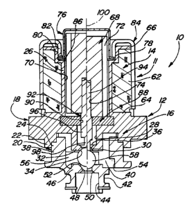
With particular reference to FIGS. 1 and 3, ON/OFF solenoid valve
assembly 10 is shown to include a set of universal components that can be
assembled into a base assembly 12 which is common to both normally-open
5 solenoid valve 11 and normally-closed solenoid valve 11'. In general, base
assembly 12 includes a solenoid 14 and a valve body 16. Valve body 16 is a two-
piece assembly comprised of a body member 18 and a nose member 20. Body
member 18 includes an annular stepped mounting flange 22 that is adapted to
receive a corresponding annular stepped mounting flange 24 on nose member 20.
10 Suitable means (i.e., welding, fasteners, etc.) are used for securing mounting
flanges 22 and 24 together to provide a fluid tight seal between body member 18
and nose member 20. Body member 18 also is formed to include an upstanding
tubular bobbin 26, a central control chamber 28, a flow passageway 30 formed
through an end segment 32 and which communicates with control chamber 28, and
15 first and second ball seats 34 and 36, respectively, which are defined by chamfered
edge surfaces formed on opposite ends of flow passageway 30.
Nose member 20 includes a first tubular portion 38 defining a fluid
chamber 40, a second tubular portion 42 defining an inlet port 44, and an
intermediate wall portion 46 interconnecting first tubular portion 38 to second tubular
20 portion 42 with a flow passageway 48 providing a fluid communication pathway
between inlet port 44 and fluid chamber 40. As will be appreciated, inlet port 44 is
adapted to be coupled to any suitable inlet or supply line of a fluid-controlled system.
- 21 99861
~ .
Attorney Docket: 1203-00086
Nose member 20 also includes first and second valve seats 50 and 52, respectively,
formed as chamfered edge surfaces along opposite ends of flow passageway 48,
and a pair of outlet ports 54 communicating with fluid chamber 40. Similarly, outlet
ports 54 are adapted to be coupled to any suitable outlet, discharge, or return line
of the fluid-controlled system. Furthermore, a pair of guide fingers 56 are provided
on opposite sides of fluid chamber 40 for the purpose of retaining a valve ball 58 of
normally-open solenoid valve 11 or an actuator plate 60 of normally-closed solenoid
valve 11' centrally within fluid chamber 40 for movement therein. As seen, each
guide finger 56 has an arcuate shape with its terminal end generally aligned with an
edge of one of outlet ports 54. Guide fingers 56 can be integral projections formed
to extend into fluid chamber 40 from the inner wall of first tubular portion 38 of nose
member 20 or, in the alternative, can be extensions of a separate bifurcated
component mounted therein.
As noted, base assembly 12 of ON/OFF solenoid valve 10 includes
solenoid 14 which is comprised of a coil winding 62 encircling bobbin 26 betweena radial surface 64 on body member 18 and a radial end flange 66 of bobbin 26.
The ends of coil winding 62 are conneded to blade-like terminals (not shown) which,
in turn, are connected to a remote electrical power source that is operable to supply
an electrical signal for selectively energizing coil windings 62. An armature 68 is
disposed within a long central aperture 70 of bobbin 26. Armature 68 has a plurality
of longitudinally-extending radial vanes 72 extending outwardly therefrom and a
central bore 74 formed in a first end thereof. A cap 76 is provided to enclose a
2 1 9 9 8 6 1
At~omey Docket: 1203 00086
seco"J end of armature 68. Cap 76 incl ~es a radial flange 78 that is received in an
outwardly stepped portion 80 of bobbin 26 and held in place by a bent-over flange
~,o, lion 82 of a cup-sl ,aped housing 84 the remainder of which e"closes coil winding
60. The Gl ~l ~ositl3 end of housing 84 is secured to body me" Iber 18. A washer 86 is
shown inter,.osed bet~een s~er.l ~ed ,~OI liol l 80 of bobbin 26 and radial flange 78 of
cap 76 for assistiny in preventing dirt infillr~tion. Finally a flux plate 88 is f~i~pose-
between body ",el,lLer 18 and armature 68 and inc~ldes a central opening 90.
EnerlJi~ ~lion of coil winding 62 causes an attractive ,nay, lelic force to be exel led on
armature 68 for urging it to move toward flux plate 88. This action occurs through a
",a~n~tic conduction or flux path in which magnetic fields are l,ansfe"ed from the
housing 66 across the radial working air gap to the armature 68 across the working
air gap to the flux plate 88. Thus the above-described components define base
assemLly 12 of ON/OFF solenoid valve 10 according to the ,uferer-ed embodiment of
the present invention. Base assemLly 12 of ON/OFF solenoid valve 10 is readily
ada~.i . e for use with a set of special compone,)t:j for assembly of either normally-
open solenoid valve 11 or a normally-closed solenoid valve 11 as will be described
herei.1atler with respect to FIGS. 1-2 and 3-4 respectively.
NORMALLY-OPEN SOLENOID VALVE
In normally-open solenoid valve 11 as shown in FIGS. 1 and 2 the
above-noted universal components of base assenlLly 12 are combined with a
21 9986 1
., .
Attorney Docket: 1203-00086
special component, namely a normally-open (N.O.) rod 92. N.O. rod 92 includes a
first end segment 94 which is fixedly mounted in central bore 74 of armature 68.N.O. rod 92 also includes a larger diameter intermediate segment 96 which is
slidingly received in central opening 90 of flux plate 88 and establishes a sealed fit
therewith. Finally, N.O. rod 92 includes a reduced diameter second end segment
98 which extends longitudinally from intermediate segment 96 and engages valve
ball 58 which, in turn, is disposed in fluid chamber 40 for movement between first
ball seat 34 of body member 18 and second valve seat 52 of nose member 20. As
noted, the curved terminal end portions of guide fingers 56 are oriented to guide
valve ball 58 for movement in fluid chamber 40 between positions of engagement
with one of first ball seat 34 and second valve seat 52.
A central axis of normally-open solenoid valve 11 is illustrated in FIG.
1 by reference numeral 100 with the movable components of solenoid valve 11
shown on the left side of axis 100 in their non-actuated "normally-open" state
positions and shown on the right side of axis 100 in their actuated "closed" state
positions. Specifically, in the left half portion of FIG. 1, the normally-open
configuration of ON/OFF solenoid valve 10 is shown with solenoid 14 in a de-
energized state wherein armature 68 and N.O. rod 92 are located in a valve "open"
position such that valve ball 58 is displaced from second valve seat 52 of nose
member 20, thus allowing fluid to flow through inlet port 44 into fluid chamber 40
and out of outlet ports 54. Due to the pressure of the fluid acting on valve ball 58
within flow passageway 48, valve ball 58 is forcibly pressed against first ball seat 34
2 1 ~6 1
Attorney Docket: 1203-00086
of body member 18 when solenoid 14 is in its de-energized state. As such, valve
ball 58 seals flow passageway 30 for preventing fluid from entering control chamber
28. However, when solenoid 14 is energized by supplying an electrical signal to coil
winding 62 of ON/OFF solenoid valve 10, the magnetic fields generated cause
5 armature 68 and N.O. rod 92 to move toward a valve "closed" position, as shown
in the right half portion of FIG.1. As N.O. rod 92 moves to its valve closed position,
its second end segment 98 forces valve ball 58 against second valve seat 52 of
nose member 20, thereby interrupting the flow of fluid from inlet port 44 into fluid
chamber 40.
10Assembly of normally-open solenoid valve 11 requires inserting valve
ball 58 in fluid chamber 40 between guiding fingers 56 of nose member 20 prior to
mating flange 24 of nose member 20 with flange 22 of body member 18. In
addition, first end segment 94 of N.O. rod 92 is inserted into central bore 74 of
armature 68. N.O. rod 92 and armature 68 are then inserted into tubular portion 70
15of bobbin 26 such that intermediate segment 96 of N.O. rod 92 is received in central
opening 90 of flux plate 88 and control chamber 28 of body member 18. Cap 76 is
then placed over the end of armature 68 so that radial flange 78 abuts against
stepped portion 80 of bobbin 26. Housing 84 is then inserted over coil winding 62
and fixed to body member 18. Alternatively, if housing 84 is previously mounted to
20 enclose coil winding 62, then its flange portion 82 can be subsequently staked to
entrap cap flange 78.
- 10-
21 99861
Attorney Docket: 1203-00086
NORMALLY-CLOSED SOLENOID VALVE
With reference to FIGS. 3 and 4, the special components used in
association with the above-described base assembly 12 for assembling normally-
closed solenoid valve 11 ' will be described. In FIG. 3, base assembly 12 of ON/OFF
5 solenoid valve 10 is shown combined with special components including a normally-
closed or N.C. rod 102, valve actuator 60, a second valve ball 58', and a retainer
ring 120. In comparing FIG. 3 to FIG. 1, N.C. rod 102 is generally similar to N.O.
rod 92 with the exception that second end segment 98 has been truncated
therefrom. As such, N.C. rod 102 includes a first end segment 104 fixedly received
in central bore 74 of armature 68 and a larger diameter second end segment 106
which is slidingly received in central opening 90 of flux plate 88. The terminal end
of N.C. rod 102 engages valve ball 58 which, in this arrangement, is disposed in
control chamber 28 of body member 18 for movement relative to second ball seat
36. Valve actuator 60 is disposed for sliding movement in fluid chamber 40 and is
held in place between opposing pairs of guide fingers 56. Valve actuator 60
includes a pair of longitudinally-extending support arms 110, formed at the opposite
ends of a crossrail 112, which are disposed adjacent to the outer wall of fluid
chamber 40. Valve actuator 60 also includes a first or upper projection 114 which
extends through flow passageway 30 and contacts valve ball 58 disposed in control
chamber 28 in body member 18. Valve actuator 60 also includes a second
projection 116 which extends through flow passageway 48 and contacts second
valve ball 58' disposed in inlet port 44. Second ball 58' is movable with respect to
- 11 -
2 1 9986 1
.. .
Attorney Docket: 1203-00086
first valve seat 50 of nose member 20. Retainer plate 120 is a ring-like member
provided for retaining second valve ball 58' within inlet port 44.
A central axis 100' is provided such that the left half portion of FIG. 3
illustrates the de-energized state of solenoid 14 in normally-closed solenoid valve
11'. In the de-energized state, armature 68 and N.C. rod 102 are located in a valve
"closed" position with armature 68 displaced from flux plate 88. With armature 68
and N.C. rod 102 in the valve closed position, the fluid pressure within inlet port 40
acts on second valve ball 58' which, in turn, causes projection 114 on actuator 60
to hold valve ball 58 in a position away from second ball seat 36 of base member18, thus locating valve actuator 60 in its corresponding normally closed position.
When valve actuator 60 is in its normally closed position, second valve ball 58' is
seated against first valve seat 50 of nose member 20, thus closing inlet port 44 from
communication with fluid chamber 40.
As shown in the right half portion of FIG. 3, solenoid 14 of ON/OFF
solenoid valve assembly 10 is shown in an energized state wherein armature 68 and
N.C. rod 102 are caused to move toward flux plate 84 to a valve "open" position.As N.C. rod 102 moves to its valve open position, it forces valve ball 58 against
second ball seat 36 of body member 18, thereby closing flow passageway 30. As
valve ball 58 is forced against second ball seat 36 of body member 18, valve
actuator 60 is forced to slide downwardly to its valve open position, thereby forcing
second valve ball 58' away from first valve seat 50 and thus allowing fluid to flow
through inlet port 44 into fluid chamber 40 and out through outlet passages 54.
- 12-
2 1 998~ 1
Attorney Docket: 1203-00086
Assembly of normally-closed solenoid valve 11' requires inserting valve
ball 58 in control chamber 28 of body member 18 prior to inserting flux plate 88therein. First end segment 104 of N.C. rod 102 is then inserted into central bore 74
of armature 68. N.C. rod 102 and armature 68 are then inserted into bobbin 26
such that second end segment 106 of N.C. rod 102 is received in central opening
90 of flux plate 88. Cap 76 is then placed over the end of armature 68 so that the
radial flange 78 abuts against stepped portion 80 of bobbin 26. Housing 84 is then
inserted over stationary coil 62. Prior to mating nose member 20 with base member
18, valve actuator 60 is inserted in fluid chamber 40 between guide fingers 56.
Nose member 20 is then mated with body member 18 and second valve ball 58' is
placed in inlet port 44 of nose member 20 and retainer plate 120 is installed. Means
can optionally be provided for securing second ball 58' in cylindrical inlet port 44.
For example, the outer edge of cylindrical inlet port 44 can be swaged in order to
provide a diameter small than that of second valve ball 58'.
As can be understood from the above description, ON/OFF solenoid
valve assembly 10 is provided with a base assembly 12 comprised of common or
"universal" elements which can be used for assembly either of normally-open
solenoid valve 11 or normally-closed solenoid valve 11'. Furthermore, ON/OFF
solenoid valve assembly 10 requires the interchange of a minimal number of special
parts in order to achieve a normally-closed or a normally-open arrangement. The
common usage of the universal components of ON/OFF solenoid valve assembly
10 will allow a manufacturer to reduce the overall machinery and manpower required
2 1 9986 ~
Attorney Docket: 1203-00086
for manufacturing both normally-open and normally-closed solenoid valves. In
addition, the storage space required for maintaining a ready stock of valve assembly
components is greatly reduced since a manufacturer no longer is required to store
solenoid valve components for separately designed normally-open and normally-
5 closed solenoid valves. In addition, because valve balls 58 and 58' are preferablyof the same diameter, only one stock of such valve balls is required.
The assembly of either of normally-open solenoid valve 11 or normally-
closed solenoid valve 11' is very simple according to the present invention.
Although the order in which parts are assembled varies, no special machinery is
10 required for fastening the components together. The invention being thus described,
it will be obvious that the same may be varied in many ways. Such variations are
not to be regarded as a departure from the spirit and scope of the invention, and all
such modifications as would be obvious to one skilled in the art are intended to be
equivalent within the scope of the following claims.
- 14-