Note: Descriptions are shown in the official language in which they were submitted.
CA 02200024 1999-03-15
BACKGROUND OF THE INVENTION
Field of the Invention
This invention relates to an apparatus for applying a flexible adhesive
strip around the perimeter edge of a rigid substrate. More particularly, the
present
invention relates to an improved apparatus for applying an insulating edge
strip
onto glass sheets as part of the manufacturing process of insulating glass
units.
Description of the Prior Art
To simplify the production of insulating glass units, various adhesive
strip products have been developed. One such product is described in US Patent
l0 4,831,799. The product is manufactured from flexible thermoset rubber foam
that
incorporates desiccant fill material and features a vapor barrier backing film
and
acrylic side adhesive. The side adhesive is protected by a flexible release
liner
that allows the material to be packaged on reels. This adhesive strip product
has
been commercialized by Edgetech I.G. Inc. and is marketed under the Trademark
of SuperSpacer~.
For the production of insulating glass units, the adhesive strip
product is applied around the perimeter edge of a glass substrate. To provide
continuity of the vapor barrier at the corners, a notch is made at the corners
and
this creates a flex point that allows for easy corner formation.
2 o Various application tools have been developed for forming these
notched corners and one way of forming these corner notches is through the use
of a slidable circular punch. When activated, the hollow punch removes a half
circular portion or slug of strip material. Because of the acrylic side
adhesive,
these slugs adhere together and as a result, the slug material can be easily
ejected from the tool. The advantage is that the tool can remain in continuous
72112-42
CA 02200024 1999-03-15
contact with the glass and the productivity of strip application is improved.
At the final corner, there are further productivity advantages if the
tool can also incorporate a blade for cutting through the adhesive strip. As
described in U.S. Patent 5,472,558 Lafond, one approach is add a separate
blade
that operates in combination with the punch to both notch and cut through the
adhesive strip at the final corner. Although productivity is improved,
experience
has shown that this simultaneous operation of the punch and cutting blade
requires a complicated punch design that is expensive to manufacture and is
prone to wear and damage.
1 o The tool of U.S. 5,472,558 Lafond is also limited to producing a
notched corner. An alternative corner application detail is to partially cut
through
the back face of the adhesive strip and create an open-ended corner. Although
in
this arrangement the barrier film is not continuous, the open-ended corner
allows
for additional sealant material to be applied at the corners and this ensures
that
the edge-seal integrity of the insulating glass unit is not downgraded.
SUMMARY OF THE INVENTION
The invention provides a tool for applying strip material to a substrate
having an edge and a major face, said strip material having a flexible body
and an
exterior face, comprising: a tool body having a lower surface and a channel
2 o extending therethrough for receiving strip material therein; a substrate
positioning
member adjacent said channel on said lower surface of said tool body for
guiding
said tool along the edge of said substrate, said lower surface of said tool
body
being elevated from said major face when said strip material is fed through
said
channel; and cutting means for cutting into an exterior surface of said
flexible body
of strip material to permit said flexible body to be bent about a corner.
- 2 -
72112-42
CA 02200024 2000-O1-27
72112-42(s)
The invention also provides a hand tool for applying
strip material to a substrate having an edge and a major face
comprising: a tool body having a lower surface and a channel
extending therethrough for receiving strip material therein; a
substrate positioning member adjacent said channel on said
lower surface of said tool body for guiding said tool along the
edge of said substrate, said substrate positioning member
comprising longitudinally oriented guide members, a front
portion of said lower surface of said tool body being elevated
from said major face when said strip material is fed through
said channel; cutting means on said tool body for selectively
slit-cutting a desired depth of said strip material; and
actuation means on said tool body for actuation of said cutting
means.
The invention further provides a method of placing a
strip of material proximate an edge of a substrate having a
major face comprising the steps of: providing a length of
sealant strip having a non-metallic body from a supply thereof;
providing a tool having a lower surface and strip feeding
channel extending therethrough and further provided with
cutting means adapted to cut into said strip; feeding a length
of said strip into said channel such that said lower surface is
elevated from said major face; effecting securement of said
strip to said edge of said substrate; and cutting said strip
part-way into the body thereof on an exterior surface thereof
with said tool at a corner of said substrate to permit bending
of said strip around a corner edge of said substrate.
The present invention additionally provides a hand
tool for applying adhesive strip material to a substrate having
an edge and a major face, comprising: a body having a lower
surface and a channel extending therethrough for receiving
strip material therein; a positioning member adjacent to said
channel on said lower surface of said body for guiding said
- 3 -
CA 02200024 2000-O1-27
72112-42(s)
tool along said edge of said substrate, said lower surface of
said body being elevated from said major face when said strip
material is fed through said channel; a pressure wheel that can
be adjusted in position for applying pressure on said strip
material, said pressure wheel being mounted in said body; a
punch means mounted in said body and selectively operable for
removing a portion of said strip material; and a mechanism for
shifting alignment of said strip material in said channel so
that said punch can selectively cut through said strip
to material.
The body and handle of the tool are preferably
ergonomically shaped for comfort in use and to allow engagement
of the tool by multiple and changing hand positions. The punch
is preferably selectively operated by the fingers or thumb of
the hand in which the tool is held, suitable actuators
requiring pushing action from a finger or thumb onto a lever or
button.
The components of the hand tool are detachable, and
the tool has a body to which the components can be attached for
20 use in right handed or left handed mode. The tool includes a
removable front face plate which at its lower
end incorporates a slot at the top of which is a roller for
guiding the strip into the tool channel, the face plate also
including a large opening through which slugs cut from the
strip by the punch are ejected.
The lower face of the tool is preferably provided as
a removable wear plate, and the positioning member as a
reversible pad that is releasably attached to the lower surface
of the body, these parts being of plastic material which will
30 minimize damage to the substrate.
The pressure wheel is height adjustable preferably by
means of a finger-actuated rotatable nut wheel engaging a
threaded stem on which the pressure wheel is carried.
- 4 -
CA 02200024 1999-03-15
The invention will further be described, by way of example only, with
reference to the embodiments illustrated in the accompanying drawings.
BRIEF DESCRIPTION OF DRAWINGS
Figure 1 is a top perspective view of a hand tool for adhesive strip
application on a horizontal work surface and incorporating a punch for corner
notching and strip cut-off.
Figure 2 is a front cross section through the hand tool for horizontal
strip application taken on the line II-II in Figure 3.
Figure 3 is a side cross section through the hand tool for horizontal
to strip application taken on the line III-III in Figure 2.
Figure 4 is a top perspective detail of the adjustable wheel.
Figure 5 is a sectional plan view of the push-over block taken on the
line V-V in Figure 3 with the punch positioned for the removal of a portion of
the
adhesive strip.
Figure 6 is a view similar to Figure 5 of the push-over block with
punch positioned to cut through the adhesive strip material.
Figure 7 is a bottom perspective view of a corner locator and the
lower surface of the hand tool.
Figure 8 is a top perspective view of the adhesive strip application
2 o with an open-sided corner detail.
Figure 9 is a top perspective cross section view of the push-over
block with chisel blade positioned for the partial cut-through of the adhesive
strip.
Figure 10 is a view similar to Figure 9 showing the chisel blade
positioned for complete cut-through of the adhesive strip material.
DETAILED DESCRIPTION OF THE DRAWINGS
- 5 -
72112-42
CA 02200024 1999-03-15
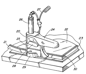
Referring to the drawings, Figure 1 shows a top perspective view of a
hand tool generally represented by numeral 20, that is used to apply a
flexible
adhesive strip 21, around the perimeter edge of a rigid, horizontally-
positioned,
glass sheet 22. The adhesive strip 21 is backed by a vapor barrier film 23.
The hand tool 20 consists of a removable handle 24, a central body
portion 25 and a pneumatic cylinder 26. An airline 27 supplies pressurized air
to
the cylinder 26. As discussed in detail later, the pneumatic cylinder
activates a
hollow circular punch that removes a semi-circular piece of material known as
a
slug from the adhesive strip 21. This feature allows the strip 21 to be bent
or
to flexed about a corner 30 and also ensures that the vapor barrier backing 23
of the
strip is continuous. The push-over block can shift alignment of the strip 21
so that
at the final corner, the punch can completely cut through the strip 21. The
push
bar 29 is operated through a thumb or finger pushing action.
Figure 2 shows a front cross section through the hand tool 20 for
horizontal strip application. The body 25 is manufactured in part from a U-
shaped
metal channel 40 and has a lower surface 41. A removable base plate 42 is
attached to the U-shaped metal channel 40. To prevent scratching or accidental
chipping of the glass sheet 22, the base plate 42 extends over the entire
lower
surface 41 and the base plate is also manufactured from a smooth plastic
material
2 o such as Teflon or polyacetal plastic.
An alignment bar 43 is attached to the base plate 42 and extends the
length of the lower surface 41. The alignment bar 43 is also manufactured from
a
smooth, durable plastic that provides for sliding guided contact on the
perimeter
edge 44 of the glass sheet 22. Because the plastic alignment bar 43 is subject
to
extensive wear, the strip is reversible and is also made from a durable
plastic
- 6 -
72112-42
CA 02200024 1999-03-15
material such as polyacetal. A U-shaped cradle or push-over block 45 is
positioned between the two side walls 46 of the U-shaped metal channel 40. The
push-over block 45 is operated by means of a push-bar 29 to which it is
connected by tubular supports 65 guided in bores in the right hand side wall
as
seen in Figure 2.
The removable handle 24 is held in place by the pneumatic cylinder
26 that is screwed into and supported by the U-shaped metal channel 40. The
cylinder 26 is centrally located on the U-shaped channel 40 and this ensures
that
the tool weight is balanced so that the tool can be comfortably held in the
hand.
to To provide for multi-positional handling of the tool, tubing connections
are kept to
a minimum and this is achieved by using a spring-return type pneumatic
cylinder
26. The air supply line 27 is connected to a ball valve 47 that is located
between
the two side walls 46 of the U-shaped metal channel 40. A lever bar 28 is
connected to a ball valve 47. A second air line 48 connects the ball valve 47
to
the pneumatic air cylinder 26. Mounted within the cylinder 26 is a piston that
moves back and forth when activated.
When the tool is in operational use, the adhesive strip is guided to
pass through the U-shaped push-over block 45. Attached to the piston shaft 51
is
a two-piece punch assembly 52 that consists of a punch block 53 and a punch
2 o knife 54. When activated, the punch assembly 52 moves vertically downwards
to
a punch pad 49 at the bottom of the push-over block 45. To prevent the
adhesive
strip from adhering to the punch pad 49, the pad is manufactured from low-
friction
material such as Teflon.
Figure 3 shows a side cross section through the hand tool for
horizontal strip application. Attached to U-shaped metal channel 40 is a
_ 7 _
72112-42
CA 02200024 1999-03-15
removable front face plate 56. During the corner-notching operation, the punch
blade 54 when depressed removes a part-circular slug of material from the
adhesive strip. Because of the side adhesive on the strip, the part circular
slugs
successively removed adhere together and form a half cylindrical tube that is
ejected through a slot 55 in the front face plate 56. Both sides of the front
face
plate 56 slot are smoothly contoured and direct the part-circular tube of slug
material away from the glass substrate 21. The front face plate 56 also
incorporates a roller 58 between the sides of a slot in the front face that
helps to
direct and hold down the adhesive strip at the entry point 59. To prevent the
roller
l0 58 from sticking to the adhesive strip, the roller 58 is manufactured from
Teflon
plastic.
When the tool is in operational use, the adhesive strip passes
beneath the roller 58 and through the U-shaped push-over block 45. The strip
is
then channelled between laterally spaced plastic spacer pieces 70 and 71
(Figure
5) and beneath an adjustable pressure wheel 60. The pressure wheel 60 rides on
the adhesive strip and ensures that the base plate 42 is not in direct contact
with
the glass sheet 22.
Figure 4 shows a top perspective detail of the adjustable wheel 60.
Because of varying heights of adhesive strip, it is important that the spacing
2 o between the pressure wheel 60 and the glass sheet 22 can easily be
adjusted and
this is achieved through means of a nut in the form of a finger knob 61 that
can be
rotated through finger action to raise or lower the pressure-wheel threaded
shaft
62. To prevent the free rolling pressure wheel 60 from sticking to the
adhesive
strip 21, the wheel is made from Teflon plastic.
Figure 5 shows the push-over block 45 as set up in its rest position
72112-42
CA 02200024 2000-O1-27
72112-42(s)
for the corner notching operation. The adhesive strip 21
passes through the U-channel push-over block 45. The push-
over block 45 is located between the two side walls 46 of the
metal U-shaped channel 40. To cradle the adhesive strip
during the corner notching and cut-off operations, the push-
over block 45 incorporates two part cylindrical cut-outs 63
and 64. One side of the push-over block is connected by the
two tubular metal supports 65 that pass through a side wall 46
of the metal U-channel 40 and are connected to the push bar
29. The other side 67 of the push-over block 45 is pressed
against by a spring 69 that is anchored to the adjacent side
wall 46 of the metal U-channel.
When the tool is in operational use, the adhesive
strip 21 passes through an entry point 59 in the front face
plate 56 and then passes through the U-shaped push-over block
45. When activated, the punch knife 54 removes a half
circular material slug 68 from the front face of the adhesive
strip 21. The plastic infill panels 70 and 71 guide the
adhesive strip 21 through the open channel. The adhesive
strip 21 is then directed downwards through a slot 98
(Figure 7) in the base plate and is then adhered to the glass
substrate by means of the adjustable pressure wheel 60.
Figure 6 shows the push-over block 45 as set up for
the final cut-off operation. By applying finger or thumb
pressure to the push bar 29, the spring 69 is compressed and
the push-over block 45 is moved over. As a result, the
adhesive strip 21 is shifted out of alignment and the punch
blade 54 is centrally located above the adhesive strip 21.
When activated, the punch blade 54 cuts through and severs the
strip 21.
To facilitate this lateral displacement of the
adhesive strip 21, the plastic infill panel 71 features a
- 9 -
CA 02200024 2000-O1-27
72112-42(s)
chamfered corner edge 71a. Another key feature is that
because following the cut-off operation, the adhesive strip
material can be held within the tool by maintaining the block
45 displaced as shown in Figure 6 where it presses the strip
against the edge of the entry point 59 and so there is no need
to rethread the adhesive strip through the open channel within
the tool to start a subsequent operation.
For different strip widths there is a requirement
for different punch sizes. For a 1/4" width spacer strip, a
3/8" diameter punch is typically used while for a 3/16" width
spacer strip, a 5/16" diameter punch is typically used.
Side holes (not shown) in the strip 21 are used for
gas filling the final assembled insulating glass unit and this
process involves inserting special probes and lances through
the side holes. Although the side holes can be made after the
adhesive strip 21 is applied to the glass units, there are
productivity advantages if the holes are fabricated during
strip application. For this purpose an auxiliary gas fill
punch (not shown) is attached to the side of the hand tool 20
and supported by the side walls 46 of the U-shaped metal
channel.
Figure 7 illustrates another optional feature of the
hand tool which is a corner locator pin. Typically for corner
location, the operator uses an alignment line 99 engraved on
the side wall surface of the tool. An alternative approach is
to use a corner locator pin 85 which is incorporated within
the alignment bar 43. The locator pin 85 which is spring-
activated helps the operator to locate the corner 30 of the
glass sheet 22 (i.e. is spring biased to an outwardly
projecting position from an inwardly compressed position).
When the tool 20 is in operational use, the spring-
- 10 -
CA 02200024 2000-O1-27
72112-42(s)
activated locator pin 85, pops out after the front end of the
alignment bar 43 has passed the corner 30 of the glass sheet
22. The operator can then backtrack the tool a slight
- 10a -
CA 02200024 1999-03-15
distance and hold the corner locator pin 85 firmly against the glass edge 44.
Figure 8 shows an alternative corner detail for adhesive strip
application. Generally, to ensure that the vapor barrier 23 is continuous at
the
back face 87, the preferred application detail is to corner notch the adhesive
strip
21. When the adhesive strip 21 product is backed by a low permeable outer
sealant, an alternative corner application detail is to partially cut through
the back
face 87 of the adhesive strip as shown in Figure 8. Although the barrier film
23 is
not continuous, the open-ended corner 88 allows for additional sealant
material to
be applied at the corner and thus ensures that the edge-seal integrity of the
to insulating-glass unit is not downgraded.
Figure 9 is a top perspective cross-section view of an alternative
push-over block 89 which cooperates with a chisel blade 90 (instead of the
punch
blade) to produce the corner 88 of Figure 8. The chisel blade 90 is attached
to a
blade block 91 which in turn is attached to the piston shaft 51. When
activated,
the chisel blade 90 partially cuts through the back face of the adhesive strip
21.
Figure 10 is also a top perspective cross-section of the push-over
block 89 with a chisel blade 90. Through thumb or finger pressure on the push
bar 29, the push-over block 89 is moved over and when activated, the chisel
blade
90 fully cuts through the adhesive strip 21.
2 o Although Figures 2 to 10 show cross sections, plans, and perspective
details of the hand tool for horizontal strip application by a right handed
person, it
can be appreciated by those skilled in the art that the tool is modular in
design
and can be easily modified for other operations. The main structural support
for
the tool is the U-shaped metal channel 40. By adding on different components
such as handles, front face plates, back support plates and punch pieces, the
tool
- 11 -
72112-42
CA 02200024 1999-03-15
operation can be modified from horizontal to vertical application, from right
to left-
handed use and from punch blade to chisel blade function.
In Figures 1 to 10 when describing the product inventions, specific
reference is made to the adhesive strip product, SuperSpacer (Trademark),
manufactured by Edgetech I.G. Inc. Although the equipment has been
specifically
developed for this product, it should be apparent to those skilled in the art
that the
inventions described have wide application and are not limited to this
particular
adhesive strip product.
- 12 -
72112-42