Language selection

Search

Patent 2200035 Summary

Third-party information liability

Some of the information on this Web page has been provided by external sources. The Government of Canada is not responsible for the accuracy, reliability or currency of the information supplied by external sources. Users wishing to rely upon this information should consult directly with the source of the information. Content provided by external sources is not subject to official languages, privacy and accessibility requirements.

Claims and Abstract availability

Any discrepancies in the text and image of the Claims and Abstract are due to differing posting times. Text of the Claims and Abstract are posted:

  • At the time the application is open to public inspection;
  • At the time of issue of the patent (grant).
(12) Patent: (11) CA 2200035
(54) English Title: ELECTRIC HEAT PEN FOR GOLD-BLOCKING AND HEAT SEALING PURPOSES
(54) French Title: CRAYON CHAUFFANT POUR ESTAMPAGE A L'OR ET SOUDAGE THERMIQUE
Status: Expired and beyond the Period of Reversal
Bibliographic Data
(51) International Patent Classification (IPC):
  • B29C 65/30 (2006.01)
  • B29C 65/18 (2006.01)
  • B44B 05/02 (2006.01)
  • B44B 11/04 (2006.01)
  • B44C 01/24 (2006.01)
  • H05B 03/00 (2006.01)
(72) Inventors :
  • CHOU, AMMY (Taiwan, Province of China)
(73) Owners :
  • AMMY CHOU
(71) Applicants :
  • AMMY CHOU (Taiwan, Province of China)
(74) Agent: SMART & BIGGAR LP
(74) Associate agent:
(45) Issued: 2000-05-30
(22) Filed Date: 1997-03-14
(41) Open to Public Inspection: 1998-09-14
Examination requested: 1997-03-14
Availability of licence: N/A
Dedicated to the Public: N/A
(25) Language of filing: English

Patent Cooperation Treaty (PCT): No

(30) Application Priority Data: None

Abstracts

English Abstract


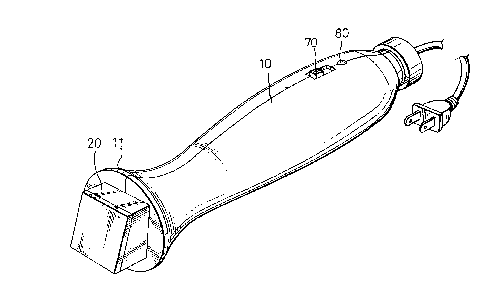
An electric heat pen including a pen base adapted for
the holding of the hand, a pen head fixedly mounted on one
end of the pen base and holding a hot plate on the outside,
two plate conductors and an electric heating element between
the plate conductors on the inside, and a switch controlled
to connect electric power supply to the electric heating
element through the plate conductors, causing the electric
heating element to produce heat for heating said hot plate
for golf-blocking or heat sealing.


French Abstract

Crayon chauffant électrique comprenant une base pour le crayon adaptée à la prise de la main, une tête fixée à une extrémité de la base et retenant une plaque chauffante à l'extérieur, deux conducteurs de plaque et un élément chauffant électrique situé entre les conducteurs de plaque à l'intérieur et un commutateur contrôlé pour raccorder l'alimentation d'énergie électrique à l'élément chauffant électrique par les conducteurs de plaque, permettant à l'élément chauffant électrique de produire de la chaleur pour chauffer la plaque chauffante pour un estampage à l'or ou un soudage thermique.

Claims

Note: Claims are shown in the official language in which they were submitted.


What the invention claimed is:
1. An electric heat pen comprising:
a pen base adapted for the holding of the hand;
a pen head fastened to one end of said pen base and
defining a receiving chamber;
an electric heating element mounted inside the
receiving chamber of said pen head and electrically connected
to produce heat;
an upper conductor and a lower conductor respectively
disposed in contact with said electric heating element, said
electric heating element being actuated to produce heat when
said upper conductor and said lower conductor are
respectively connected to two opposite terminals of power
supply; and
a hot plate covered on said receiving chamber of said
pen head and adapted to receive heat from said electric heating
element.
2. The electric heat pen of claim 1 wherein said upper
conductor and said lower conductor are respectively made from
heat conductive aluminum plate, and said electric heating
element is a positive temperature coefficient plate resistor
retained between said upper conductor and said lower
conductor.
3. The electric heat pen of claim 1 wherein said hot
plate is a heat conductive aluminum plate, and an electrically
insulative heat resisting film is sandwiched in between said
hot plate and lower conductor.
4. The electric heat pen of claim 1 wherein said
receiving chamber of said pen head is covered with a top cover,
and a spring plate is mounted inside said receiving chamber,
and attached to said top cover to impart a downward pressure
to said upper conductor against said electric heating element
and said lower conductor.
5. The electric heat pen of claim 4 wherein a steel
plate is sandwiched in between said spring plate and said upper
conductor, and an electrically insulative heat resisting film
is sandwiched in between said upper conductor and said steel

plate.
6. The electric heat pen of claim 1 wherein said pen
base is mounted with a switch adapted for controlling the
connection of external power supply to said upper and lower
conductors, and an indicator light controlled by said switch.
7. The electric heat pen of claim 1 wherein said pen
base has a stop flange raised around the periphery at one end
adjacent to said pen head.
8. The electric heat pen of claim 1 wherein said pen
base and said pen head are respectively made from heat
resisting plastic.

Description

Note: Descriptions are shown in the official language in which they were submitted.


CA 02200035 2000-02-22
76302-10
~A~'KGROLTN9 OF ~.uF INVENTION
$ The present invention relates to electric heat seal
apparatus, and more specifically to an electric heat pen which
can be used as a handy 'heat sealing device as well as a handy
gold-blocking press.
A varieity of heat sealing apparatus have been disclosed,
and have appeared on the market . Exemplars of these apparatus
are seen in U. S . Pat . No . 1, 650 , 690 entitled "HEAT PENCIL" ;
U. S . Pat . No . 2, 598, 900 entitled "HEAT SEALING DEVICE" ; U. S .
Pat . No . 4, 469 , 549 entitled "HEAT SEAL APPARATUS" ; U. S . Pat .
No. 5,374,806 entitled " PEN BASE ELECTRIC HEAT SEALER " .
1~ These apparatus are functional, .however they are specifically
designed for heat sealing purpose only. It is practical to
utilize the heat of a heat sealing apparatus for other
purposes.
~.tJNIMARY OF THE INVENTION
It is one obj ect of the present invention to provide
an electric heat pen.which can be used as a heat sealer as
well as a handy gold-blocking press. It is another object
of the present. invention to provide an electric heat pen which
?~ is save and convenient in use . A dual-purpose electric heat
pen according to the present invention is comprised of a pen
base, a pen read, an electric heating element, a first
conductor, a second conductor, and a hot plate . The pen base
is adapted for the holding of the hand. The pen head is fixedly
fastened to one end of the pen base. The electric heating
element is mounted in a receiving chamber def fined within the
pen head. The first conductor and the second conductor are
respectively disposed in close contact with the electric
heating element. The hot plate is fastened to the receiving
chamber of the pen head on the outside to receive heat from
the electric :heating element when the first conductor and the
second conducaor are respectively conr_ected to power supply .
i

22~003~
The pen base and the pen head can have any of a variety of
shapes. They are made from electrically insulative heat
resisting material for example electrically insulative heat
resisting plastic. A thermochromic plastic device may be
installed in the pen base at a suitable location to indicate ,
the change of temperature of the pen base . A switch and an
indicator light are respectively mounted on the pen base for
power control . The indicator light can be a bulb or LED . When
the switch is switched on, the electric heating element is
turned on to produce heat, and the indicator light is also
turned on to give an indication. Further, the pen base has
a stop flange raised around the periphery at one end adjacent
to the pen head. The stop flange prohibits the user' s fingers
from touching the hot pen head, and suspends the pen head from
the table top when the electric heat pen is lying on the table
top horizontally. The electric heating element can be a
positive temperature coefficient resistor element which can
be conveniently obtained from the market. The heating
temperature of the electric heating element can be set within
150°C to 250°C, or preferably within 200°C to
230°C.
BRIEF DESCRIPTION OF THE DRAWINGS
Fig. 1 is an elevational view of an electric heat pen
according to the present invention;
Fig. 2 is an exploded view of the pen base of the
electric heat pen shown in Figure 1;
Fig. 3 is an exploded view of the pen head of the
electric heat pen shown in Figure 1; and
Fig. 4 is a sectional view of a part of the present
invention, showing the internal arrangement of the pen head.
DETAILED DESCRIPTION OF THE PREFERRED EMBODIMENT
Referring to Figure 1, an electric heat pen in
accordance with the present invention is generally comprised
of a pen base 10, and a pen head 20. The pen base 10 is a
hollow bar mounted with an ON/OFF switch 70 and an indicator
light 80, having a stop flange 11 at one end. The pen head
2

2200035
20 is fastened to the casing 10 below the stop flange 11.
Referring to Figures 2 and 3, the pen head 20 comprises
a receiving chamber 21, a top cover wall 22 covered on the
receiving chamber at the top side, a hot plate (heat conductive
aluminum plate) 60 covered on the receiving chamber 21 at the
bottom side . There are provided a spring plate 90 , a steel
plate 100, a first plate conductor (first electrically
conductive aluminum plate) 40, a heating element 30 and a
second plate conductor (second electrically conductive
aluminum plate) 50 respectively mounted in the receiving
chamber 21 in proper order.
Referring to Figure 4, a first electrically insulative,
heat resisting film 120 is adhered to one side of the second
plate conductor 50 and closely attached to the hot plate 60;
a second electrically insulative, heat resisting film 110 is
adhered to one side of the first plate conductor 40 and closely
attached to the steel plate 100.
Referring to Figures 2 and 3 again, the first plate
conductor 40 and the second plate conductor 50 have a
respective extension strip 41151 respectively inserted
through a respective hole in the top cover wall 22 of the pen
head 20 and connected to the ON/OFF switch 70 by electric wires
130;140. The ON/OFF switch 70 is connected to an electric
plug 160 outside the pen base 10 by a cable 150. Through the
electric plug 160, AC power supply is transmitted to the
electric heat pen.
Referring to Figure 4 again, the spring force of the
spring plate 90 forces the steel plate 100 downwards toward
the hot plate 60, therefore the heating element 30 is firmly
retained in close contact between the first plate conductor
and the second plate conductor 50, and heat can be
efficiently transmitted from the heating element 30 to the
hot plate 60 through the second plate conductor 50 . The steel
plate 100 is sandwiched in between the spring plate 90 and
35 the first plate conductor 40, to evenly distribute the spring
force of the spring plate 90 to the first plate conductor 40.
Referring to Figure 4 again, the heating element 30
3

2200035
is a PTC (positive temperature coefficient) resistor element
that produces a temperature within about 200°C to 230°C upon
the passing of electric current . The hot plate 60 is a square
aluminum plate which receives heat from the heating element
30, and used for gold-blocking as well as heat sealing.
Referring to Figure 1 again, the stop flange 11 of the
pen base 10 facilitates the application of force to the pen
base 10 by the user, and prohibits the user's fingers from
touching the hot pen head 20 . Further, when the electric heat
pen is lying on the table top, the stop flange 11 suspends
the pen head 20 from the table top, and therefore the pen head
is prohibited from touching the table top.
While only one embodiment of the present invention has
been shown and described, it will be understood that various
15 modifications and changes could be made thereunto without
departing from the spirit and scope of the invention
disclosed.
4

Representative Drawing
A single figure which represents the drawing illustrating the invention.
Administrative Status

2024-08-01:As part of the Next Generation Patents (NGP) transition, the Canadian Patents Database (CPD) now contains a more detailed Event History, which replicates the Event Log of our new back-office solution.

Please note that "Inactive:" events refers to events no longer in use in our new back-office solution.

For a clearer understanding of the status of the application/patent presented on this page, the site Disclaimer , as well as the definitions for Patent , Event History , Maintenance Fee  and Payment History  should be consulted.

Event History

Description Date
Inactive: IPC from MCD 2006-03-12
Time Limit for Reversal Expired 2002-03-14
Letter Sent 2001-03-14
Grant by Issuance 2000-05-30
Inactive: Cover page published 2000-05-29
Pre-grant 2000-03-07
Inactive: Final fee received 2000-03-07
Inactive: Received pages at allowance 2000-02-22
Letter Sent 2000-01-26
Notice of Allowance is Issued 2000-01-26
Inactive: Approved for allowance (AFA) 2000-01-11
Application Published (Open to Public Inspection) 1998-09-14
Inactive: First IPC assigned 1997-07-21
Inactive: IPC assigned 1997-07-21
Request for Examination Requirements Determined Compliant 1997-03-14
All Requirements for Examination Determined Compliant 1997-03-14

Abandonment History

There is no abandonment history.

Maintenance Fee

The last payment was received on 2000-02-15

Note : If the full payment has not been received on or before the date indicated, a further fee may be required which may be one of the following

  • the reinstatement fee;
  • the late payment fee; or
  • additional fee to reverse deemed expiry.

Patent fees are adjusted on the 1st of January every year. The amounts above are the current amounts if received by December 31 of the current year.
Please refer to the CIPO Patent Fees web page to see all current fee amounts.

Fee History

Fee Type Anniversary Year Due Date Paid Date
Request for examination - small 1997-03-14
Application fee - small 1997-03-14
MF (application, 2nd anniv.) - small 02 1999-03-15 1998-11-27
MF (application, 3rd anniv.) - small 03 2000-03-14 2000-02-15
Final fee - small 2000-03-07
Owners on Record

Note: Records showing the ownership history in alphabetical order.

Current Owners on Record
AMMY CHOU
Past Owners on Record
None
Past Owners that do not appear in the "Owners on Record" listing will appear in other documentation within the application.
Documents

To view selected files, please enter reCAPTCHA code :


To view images, click a link in the Document Description column (Temporarily unavailable). To download the documents, select one or more checkboxes in the first column and then click the "Download Selected in PDF format (Zip Archive)" or the "Download Selected as Single PDF" button.

List of published and non-published patent-specific documents on the CPD .

If you have any difficulty accessing content, you can call the Client Service Centre at 1-866-997-1936 or send them an e-mail at CIPO Client Service Centre.

({010=All Documents, 020=As Filed, 030=As Open to Public Inspection, 040=At Issuance, 050=Examination, 060=Incoming Correspondence, 070=Miscellaneous, 080=Outgoing Correspondence, 090=Payment})


Document
Description 
Date
(yyyy-mm-dd) 
Number of pages   Size of Image (KB) 
Description 2000-02-21 4 184
Abstract 1997-03-13 1 17
Description 1997-03-13 4 179
Claims 1997-03-13 2 64
Drawings 1997-03-13 4 75
Representative drawing 1998-09-14 1 9
Representative drawing 2000-05-01 1 11
Reminder of maintenance fee due 1998-11-16 1 110
Commissioner's Notice - Application Found Allowable 2000-01-25 1 166
Maintenance Fee Notice 2001-04-10 1 178
Correspondence 2000-02-21 2 82
Correspondence 2000-02-14 1 24
Correspondence 2000-03-06 2 61