Sélection de la langue

Search

Sommaire du brevet 2200035 

Énoncé de désistement de responsabilité concernant l'information provenant de tiers

Une partie des informations de ce site Web a été fournie par des sources externes. Le gouvernement du Canada n'assume aucune responsabilité concernant la précision, l'actualité ou la fiabilité des informations fournies par les sources externes. Les utilisateurs qui désirent employer cette information devraient consulter directement la source des informations. Le contenu fourni par les sources externes n'est pas assujetti aux exigences sur les langues officielles, la protection des renseignements personnels et l'accessibilité.

Disponibilité de l'Abrégé et des Revendications

L'apparition de différences dans le texte et l'image des Revendications et de l'Abrégé dépend du moment auquel le document est publié. Les textes des Revendications et de l'Abrégé sont affichés :

  • lorsque la demande peut être examinée par le public;
  • lorsque le brevet est émis (délivrance).
(12) Brevet: (11) CA 2200035
(54) Titre français: CRAYON CHAUFFANT POUR ESTAMPAGE A L'OR ET SOUDAGE THERMIQUE
(54) Titre anglais: ELECTRIC HEAT PEN FOR GOLD-BLOCKING AND HEAT SEALING PURPOSES
Statut: Périmé et au-delà du délai pour l’annulation
Données bibliographiques
(51) Classification internationale des brevets (CIB):
  • B29C 65/30 (2006.01)
  • B29C 65/18 (2006.01)
  • B44B 05/02 (2006.01)
  • B44B 11/04 (2006.01)
  • B44C 01/24 (2006.01)
  • H05B 03/00 (2006.01)
(72) Inventeurs :
  • CHOU, AMMY (Taïwan, Province de Chine)
(73) Titulaires :
  • AMMY CHOU
(71) Demandeurs :
  • AMMY CHOU (Taïwan, Province de Chine)
(74) Agent: SMART & BIGGAR LP
(74) Co-agent:
(45) Délivré: 2000-05-30
(22) Date de dépôt: 1997-03-14
(41) Mise à la disponibilité du public: 1998-09-14
Requête d'examen: 1997-03-14
Licence disponible: S.O.
Cédé au domaine public: S.O.
(25) Langue des documents déposés: Anglais

Traité de coopération en matière de brevets (PCT): Non

(30) Données de priorité de la demande: S.O.

Abrégés

Abrégé français

Crayon chauffant électrique comprenant une base pour le crayon adaptée à la prise de la main, une tête fixée à une extrémité de la base et retenant une plaque chauffante à l'extérieur, deux conducteurs de plaque et un élément chauffant électrique situé entre les conducteurs de plaque à l'intérieur et un commutateur contrôlé pour raccorder l'alimentation d'énergie électrique à l'élément chauffant électrique par les conducteurs de plaque, permettant à l'élément chauffant électrique de produire de la chaleur pour chauffer la plaque chauffante pour un estampage à l'or ou un soudage thermique.


Abrégé anglais


An electric heat pen including a pen base adapted for
the holding of the hand, a pen head fixedly mounted on one
end of the pen base and holding a hot plate on the outside,
two plate conductors and an electric heating element between
the plate conductors on the inside, and a switch controlled
to connect electric power supply to the electric heating
element through the plate conductors, causing the electric
heating element to produce heat for heating said hot plate
for golf-blocking or heat sealing.

Revendications

Note : Les revendications sont présentées dans la langue officielle dans laquelle elles ont été soumises.


What the invention claimed is:
1. An electric heat pen comprising:
a pen base adapted for the holding of the hand;
a pen head fastened to one end of said pen base and
defining a receiving chamber;
an electric heating element mounted inside the
receiving chamber of said pen head and electrically connected
to produce heat;
an upper conductor and a lower conductor respectively
disposed in contact with said electric heating element, said
electric heating element being actuated to produce heat when
said upper conductor and said lower conductor are
respectively connected to two opposite terminals of power
supply; and
a hot plate covered on said receiving chamber of said
pen head and adapted to receive heat from said electric heating
element.
2. The electric heat pen of claim 1 wherein said upper
conductor and said lower conductor are respectively made from
heat conductive aluminum plate, and said electric heating
element is a positive temperature coefficient plate resistor
retained between said upper conductor and said lower
conductor.
3. The electric heat pen of claim 1 wherein said hot
plate is a heat conductive aluminum plate, and an electrically
insulative heat resisting film is sandwiched in between said
hot plate and lower conductor.
4. The electric heat pen of claim 1 wherein said
receiving chamber of said pen head is covered with a top cover,
and a spring plate is mounted inside said receiving chamber,
and attached to said top cover to impart a downward pressure
to said upper conductor against said electric heating element
and said lower conductor.
5. The electric heat pen of claim 4 wherein a steel
plate is sandwiched in between said spring plate and said upper
conductor, and an electrically insulative heat resisting film
is sandwiched in between said upper conductor and said steel

plate.
6. The electric heat pen of claim 1 wherein said pen
base is mounted with a switch adapted for controlling the
connection of external power supply to said upper and lower
conductors, and an indicator light controlled by said switch.
7. The electric heat pen of claim 1 wherein said pen
base has a stop flange raised around the periphery at one end
adjacent to said pen head.
8. The electric heat pen of claim 1 wherein said pen
base and said pen head are respectively made from heat
resisting plastic.

Description

Note : Les descriptions sont présentées dans la langue officielle dans laquelle elles ont été soumises.

CA 02200035 2000-02-22
76302-10
~A~'KGROLTN9 OF ~.uF INVENTION
$ The present invention relates to electric heat seal
apparatus, and more specifically to an electric heat pen which
can be used as a handy 'heat sealing device as well as a handy
gold-blocking press.
A varieity of heat sealing apparatus have been disclosed,
and have appeared on the market . Exemplars of these apparatus
are seen in U. S . Pat . No . 1, 650 , 690 entitled "HEAT PENCIL" ;
U. S . Pat . No . 2, 598, 900 entitled "HEAT SEALING DEVICE" ; U. S .
Pat . No . 4, 469 , 549 entitled "HEAT SEAL APPARATUS" ; U. S . Pat .
No. 5,374,806 entitled " PEN BASE ELECTRIC HEAT SEALER " .
1~ These apparatus are functional, .however they are specifically
designed for heat sealing purpose only. It is practical to
utilize the heat of a heat sealing apparatus for other
purposes.
~.tJNIMARY OF THE INVENTION
It is one obj ect of the present invention to provide
an electric heat pen.which can be used as a heat sealer as
well as a handy gold-blocking press. It is another object
of the present. invention to provide an electric heat pen which
?~ is save and convenient in use . A dual-purpose electric heat
pen according to the present invention is comprised of a pen
base, a pen read, an electric heating element, a first
conductor, a second conductor, and a hot plate . The pen base
is adapted for the holding of the hand. The pen head is fixedly
fastened to one end of the pen base. The electric heating
element is mounted in a receiving chamber def fined within the
pen head. The first conductor and the second conductor are
respectively disposed in close contact with the electric
heating element. The hot plate is fastened to the receiving
chamber of the pen head on the outside to receive heat from
the electric :heating element when the first conductor and the
second conducaor are respectively conr_ected to power supply .
i

22~003~
The pen base and the pen head can have any of a variety of
shapes. They are made from electrically insulative heat
resisting material for example electrically insulative heat
resisting plastic. A thermochromic plastic device may be
installed in the pen base at a suitable location to indicate ,
the change of temperature of the pen base . A switch and an
indicator light are respectively mounted on the pen base for
power control . The indicator light can be a bulb or LED . When
the switch is switched on, the electric heating element is
turned on to produce heat, and the indicator light is also
turned on to give an indication. Further, the pen base has
a stop flange raised around the periphery at one end adjacent
to the pen head. The stop flange prohibits the user' s fingers
from touching the hot pen head, and suspends the pen head from
the table top when the electric heat pen is lying on the table
top horizontally. The electric heating element can be a
positive temperature coefficient resistor element which can
be conveniently obtained from the market. The heating
temperature of the electric heating element can be set within
150°C to 250°C, or preferably within 200°C to
230°C.
BRIEF DESCRIPTION OF THE DRAWINGS
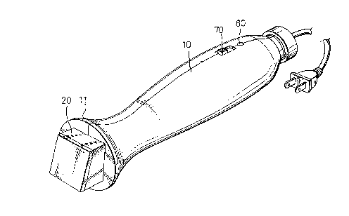
Fig. 1 is an elevational view of an electric heat pen
according to the present invention;
Fig. 2 is an exploded view of the pen base of the
electric heat pen shown in Figure 1;
Fig. 3 is an exploded view of the pen head of the
electric heat pen shown in Figure 1; and
Fig. 4 is a sectional view of a part of the present
invention, showing the internal arrangement of the pen head.
DETAILED DESCRIPTION OF THE PREFERRED EMBODIMENT
Referring to Figure 1, an electric heat pen in
accordance with the present invention is generally comprised
of a pen base 10, and a pen head 20. The pen base 10 is a
hollow bar mounted with an ON/OFF switch 70 and an indicator
light 80, having a stop flange 11 at one end. The pen head
2

2200035
20 is fastened to the casing 10 below the stop flange 11.
Referring to Figures 2 and 3, the pen head 20 comprises
a receiving chamber 21, a top cover wall 22 covered on the
receiving chamber at the top side, a hot plate (heat conductive
aluminum plate) 60 covered on the receiving chamber 21 at the
bottom side . There are provided a spring plate 90 , a steel
plate 100, a first plate conductor (first electrically
conductive aluminum plate) 40, a heating element 30 and a
second plate conductor (second electrically conductive
aluminum plate) 50 respectively mounted in the receiving
chamber 21 in proper order.
Referring to Figure 4, a first electrically insulative,
heat resisting film 120 is adhered to one side of the second
plate conductor 50 and closely attached to the hot plate 60;
a second electrically insulative, heat resisting film 110 is
adhered to one side of the first plate conductor 40 and closely
attached to the steel plate 100.
Referring to Figures 2 and 3 again, the first plate
conductor 40 and the second plate conductor 50 have a
respective extension strip 41151 respectively inserted
through a respective hole in the top cover wall 22 of the pen
head 20 and connected to the ON/OFF switch 70 by electric wires
130;140. The ON/OFF switch 70 is connected to an electric
plug 160 outside the pen base 10 by a cable 150. Through the
electric plug 160, AC power supply is transmitted to the
electric heat pen.
Referring to Figure 4 again, the spring force of the
spring plate 90 forces the steel plate 100 downwards toward
the hot plate 60, therefore the heating element 30 is firmly
retained in close contact between the first plate conductor
and the second plate conductor 50, and heat can be
efficiently transmitted from the heating element 30 to the
hot plate 60 through the second plate conductor 50 . The steel
plate 100 is sandwiched in between the spring plate 90 and
35 the first plate conductor 40, to evenly distribute the spring
force of the spring plate 90 to the first plate conductor 40.
Referring to Figure 4 again, the heating element 30
3

2200035
is a PTC (positive temperature coefficient) resistor element
that produces a temperature within about 200°C to 230°C upon
the passing of electric current . The hot plate 60 is a square
aluminum plate which receives heat from the heating element
30, and used for gold-blocking as well as heat sealing.
Referring to Figure 1 again, the stop flange 11 of the
pen base 10 facilitates the application of force to the pen
base 10 by the user, and prohibits the user's fingers from
touching the hot pen head 20 . Further, when the electric heat
pen is lying on the table top, the stop flange 11 suspends
the pen head 20 from the table top, and therefore the pen head
is prohibited from touching the table top.
While only one embodiment of the present invention has
been shown and described, it will be understood that various
15 modifications and changes could be made thereunto without
departing from the spirit and scope of the invention
disclosed.
4

Dessin représentatif
Une figure unique qui représente un dessin illustrant l'invention.
États administratifs

2024-08-01 : Dans le cadre de la transition vers les Brevets de nouvelle génération (BNG), la base de données sur les brevets canadiens (BDBC) contient désormais un Historique d'événement plus détaillé, qui reproduit le Journal des événements de notre nouvelle solution interne.

Veuillez noter que les événements débutant par « Inactive : » se réfèrent à des événements qui ne sont plus utilisés dans notre nouvelle solution interne.

Pour une meilleure compréhension de l'état de la demande ou brevet qui figure sur cette page, la rubrique Mise en garde , et les descriptions de Brevet , Historique d'événement , Taxes périodiques et Historique des paiements devraient être consultées.

Historique d'événement

Description Date
Inactive : CIB de MCD 2006-03-12
Le délai pour l'annulation est expiré 2002-03-14
Lettre envoyée 2001-03-14
Accordé par délivrance 2000-05-30
Inactive : Page couverture publiée 2000-05-29
Préoctroi 2000-03-07
Inactive : Taxe finale reçue 2000-03-07
Inactive : Pages reçues à l'acceptation 2000-02-22
Lettre envoyée 2000-01-26
Un avis d'acceptation est envoyé 2000-01-26
Inactive : Approuvée aux fins d'acceptation (AFA) 2000-01-11
Demande publiée (accessible au public) 1998-09-14
Inactive : CIB en 1re position 1997-07-21
Inactive : CIB attribuée 1997-07-21
Exigences pour une requête d'examen - jugée conforme 1997-03-14
Toutes les exigences pour l'examen - jugée conforme 1997-03-14

Historique d'abandonnement

Il n'y a pas d'historique d'abandonnement

Taxes périodiques

Le dernier paiement a été reçu le 2000-02-15

Avis : Si le paiement en totalité n'a pas été reçu au plus tard à la date indiquée, une taxe supplémentaire peut être imposée, soit une des taxes suivantes :

  • taxe de rétablissement ;
  • taxe pour paiement en souffrance ; ou
  • taxe additionnelle pour le renversement d'une péremption réputée.

Les taxes sur les brevets sont ajustées au 1er janvier de chaque année. Les montants ci-dessus sont les montants actuels s'ils sont reçus au plus tard le 31 décembre de l'année en cours.
Veuillez vous référer à la page web des taxes sur les brevets de l'OPIC pour voir tous les montants actuels des taxes.

Historique des taxes

Type de taxes Anniversaire Échéance Date payée
Requête d'examen - petite 1997-03-14
Taxe pour le dépôt - petite 1997-03-14
TM (demande, 2e anniv.) - petite 02 1999-03-15 1998-11-27
TM (demande, 3e anniv.) - petite 03 2000-03-14 2000-02-15
Taxe finale - petite 2000-03-07
Titulaires au dossier

Les titulaires actuels et antérieures au dossier sont affichés en ordre alphabétique.

Titulaires actuels au dossier
AMMY CHOU
Titulaires antérieures au dossier
S.O.
Les propriétaires antérieurs qui ne figurent pas dans la liste des « Propriétaires au dossier » apparaîtront dans d'autres documents au dossier.
Documents

Pour visionner les fichiers sélectionnés, entrer le code reCAPTCHA :


Pour visualiser une image, cliquer sur un lien dans la colonne description du document (Temporairement non-disponible). Pour télécharger l'image (les images), cliquer l'une ou plusieurs cases à cocher dans la première colonne et ensuite cliquer sur le bouton "Télécharger sélection en format PDF (archive Zip)" ou le bouton "Télécharger sélection (en un fichier PDF fusionné)".

Liste des documents de brevet publiés et non publiés sur la BDBC .

Si vous avez des difficultés à accéder au contenu, veuillez communiquer avec le Centre de services à la clientèle au 1-866-997-1936, ou envoyer un courriel au Centre de service à la clientèle de l'OPIC.

({010=Tous les documents, 020=Au moment du dépôt, 030=Au moment de la mise à la disponibilité du public, 040=À la délivrance, 050=Examen, 060=Correspondance reçue, 070=Divers, 080=Correspondance envoyée, 090=Paiement})


Description du
Document 
Date
(aaaa-mm-jj) 
Nombre de pages   Taille de l'image (Ko) 
Description 2000-02-21 4 184
Abrégé 1997-03-13 1 17
Description 1997-03-13 4 179
Revendications 1997-03-13 2 64
Dessins 1997-03-13 4 75
Dessin représentatif 1998-09-14 1 9
Dessin représentatif 2000-05-01 1 11
Rappel de taxe de maintien due 1998-11-16 1 110
Avis du commissaire - Demande jugée acceptable 2000-01-25 1 166
Avis concernant la taxe de maintien 2001-04-10 1 178
Correspondance 2000-02-21 2 82
Correspondance 2000-02-14 1 24
Correspondance 2000-03-06 2 61