Note: Descriptions are shown in the official language in which they were submitted.
2200096
APPARATUS FOR REDUCING TRANSMISSION CAPACITY
BACKGROUND OF THE lNV~NllON
1. Technical Field
The invention concerns an apparatus for reducing
the transmission capacity required to transmit signals in
bearer channels and in signalling channels of an
integrated services digital network.
2. Description of the Related Art
When signals are transmitted via an integrated
services digital network, a so-called ISDN, the
transmission capacities of the individual channels are
predetermined and cannot be changed. A bearer channel
for transmitting voice and data signals, the so-called B-
channel has a transmission capacity of 64 kbit/s. A
channel for transmitting signalling signals, the BO-
called D-channel has a transmission capacity of 16
kbit/s. Standardized transmission in the basic access
configuration provides for two B-channels and one D-
channel. Two independent integrated services digital
networks can be interconnected via a radio link for
example. Only a limited number of channels are available
in the radio link. The transmission capacity of the
individual channels is not predetermined.
Alcatel's 1994 product brochure "Alcatel 9800"
describes a subscriber access system whereby a digital
telephone network can be connected to another digital
telephone network and/or to a radio network. 1024
terminal stations for example can be connected to the
digital telephone network via 30 transmission channels of
64 kbit/s each, or via 60 transmission channels of 32
kbit/s each. The distribution into 30 or 60 transmission
channels is predetermined. The system which contains 60
transmission channels operates in accordance with the
2200096
method of adaptive differential pulse code modulation,
which can be found for example in the ITU-T
recommendation G. 726, and only supports voice services.
An ISDN link for a basic access configuration requires
two 64 kbit/s channels and one 16 kbit/s channel to
support all ISDN service features. These channels must
be provided via radio.
SUMMARY OF THE Ihv~NllON
It is therefore the task of the invention to
transmit signals via an integrated services digital
network in a more flexible manner.
According to the present invention, an apparatus
for reducing the transmission capacity required to
transmit signals in bearer channels and signaling
channels of an integrated services digital network
comprises a demultiplexer for demultiplexing the signals,
a control unit for routing the signals in the signaling
channels onward separately in transmission channels with
different transmission capacities, and a multiplexer for
multiplexing the bearer channels and the occupied
transmission channels.
In further accord with the invention, the apparatus
is characterized in that it further comprises a
simulation unit for simulating a number of terminal
stations or an exchange, and that by means of the
simulation unit, supervisory signals are transmitted in
the signaling channels.
In still further accord with the invention, the
apparatus is characterized in that it comprises an
encoding unit for encoding signals to be compressed in
the bearer channels and a switching unit whereby the
signals to be compressed or the encoded signals and the
signals not to be compressed are routed onward
separately, and that the switching unit i8 controllable
2200096
by the control unit in accordance with the contents of
the signals in the signaling channels.
Further still in accord with the invention, the
apparatus is characterized in that the encoding unit
comprises a number of voice encoders, and that voice
signals are routed via the switching unit to the encoding
unit and data signals are routed via the switching unit
to the multiplexer.
In still further in accord with the present
invention, the apparatus is characterized in that
information on current occupancy of the transmission
channels is transmitted over an additional channel
generated in the control unit.
Further in accord with the invention, the apparatus
is characterized in that it further comprises a decoding
unit for decoA~ng compressed signals and a switching unit
whereby decoded signals or signals to be decompressed,
and signals not to be decompressed are routed onward
separately, and that the switching unit is controllable
by the control unit.
According still further to the present invention,
an apparatus is characterized by being used in a radio
station.
A particular advantage of the invention is that
with a predetermined number of transmission channels,
more terminal stations able to utilize ISDN service
features can be connected to an integrated services
digital network.
Another advantage of the invention is its
compatibility with standardized modulating schemes, such
as the adaptive differential pulse code modulation.
These and other objects, features and advantages of
the present invention will become more apparent in light
of the detailed description of a best mode embodiment
thereof, as illustrated in the accompanying drawing.
2200096
BRIEF DESCRIPTION OF THE DRAWING
The invention is explained in the following by
means of a configuration example with the help of figures
1 to 3, where:
Figure 1 is a schematic illustration of a transmission
system according to the invention,
Figure 2 is a schematic illustration of an apparatus
according to the invention for reducing
transmission capacity and for compressing
signals,
Figure 3 is a schematically illustrated construction of
an apparatus according to the invention for
reducing transmission capacity and for
compressing and decompressing signals.
DESCRIPTION OF THE PREFERRED EMBODIMENTS
The configuration example is first explained by
means of figure 1 which illustrates a transmission system
SYS according to the invention. The transmission system
SYS comprises an integrated services digital network
NETl, the so-called ISDN, which i8 connected via a point-
to-multipoint connection to another network NET2, and to
four terminal stations ENDl to END4 for example.
In the integrated services digital network NETl,
signals are transmitted via bearer channels, the so-
called B-channels, and via signalling channels, the so-
called D-channels. The signals are voice, data,
signalling and packet-switched data signals. The voice
and data signals are transmitted in the bearer channels,
the signalling and the packet-switched data signals are
transmitted in the signalling channels. In a basic
access configuration a terminal station has available two
B-channels with 64 kbit/s transmission capacity each, and
one D-channel with 16 kbit/s transmission capacity. The
channel transmission capacity is predetermined.
220~oq6
The point-to-multipoint connection is preferably a
radio connection but can also be a glass, i.e., optical
fiber or a coaxial cable connection. The integrated
services digital network NETl is connected to a radio
station FSl. In the radio station the signals that are
transmitted via the integrated services digital network
NET1 are converted into radio signals. The radio signals
are transmitted via channels with variable transmission
capacity. The radio signals are simultaneously
transmitted to two further radio stations FS2 and FS3,
which determine the signals intended for them from the
transmitted radio signals by means of the time-division
multiplex method. The transmission via radio signals is
an advantage in rugged terrains, e.g. in mountains, or
with international linkups. The radio signal are
transmitted for example via radio relay links.
Voice signals which are transmitted via the
integrated services digital network NETl are compressed
in the radio station FSl before being converted into
radio signals. The signalling channels are distributed
to transmission channels with different transmission
capacities. This takes place in a unit for reducing the
transmission capacity and for compressing signals, which
is described in more detail in the text relating to
figure 2. The reduction of the transmission capacity and
the compression of the signals are used to increase the
number of channels in the radio transmission path while
maintaining the availability of all ISDN service
features.
The radio station FS2 is used to convert the
received radio signals, decompress them, adapt them to
the predetermined transmission capacity and then route
them to the network NET2. The adaptation takes place
inversely to the reduction. The network NET2 is a
3s further integrated ~ervices digital network for example.
22000~6
The radio station FS3 is used to convert the
received radio signals, decompress them, adapt them to
the predetermined transmission capacity and then route
them to the four terminal stations ENDl to END4. The
adaptation takes place inversely to the reduction. The
four terminal stations END1 to END4 are ISDN-capable
terminal stations for example.
The signals transmitted via the network NET2 are
compressed in the radio station FS2, they are divided and
converted into radio signals and are then transmitted
with the radio signals of radio station FS3 to radio
station FSl by means of the time-division multiplex
method. The radio signals of radio station FS3 originate
from the signals emitted by the terminal stations ENDl to
END4, which were previously compressed and divided. In
this way every terminal station of a network is able to
communicate with every other terminal station of another
network.
Compression of the signals takes place according to
the method of adaptive differential pulse code modulation
described in the ITU-T recommendation G. 726 for example,
or according to any other compression method.
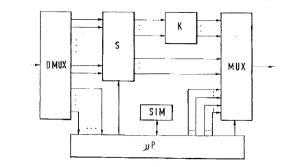
The configuration example is now explained further
by means of figure 2, which illustrates an apparatus EIN
of the invention for reducing the transmission capacity
required to transmit signals in bearer channels and in
signalling channels of an integrated services digital
network, and for compressing the signals containing
voice, data and signalling signals. The apparatus EIN
comprises a demultiplexer DMUX, a simulation unit SIM, a
switching unit S, an encoding unit K, a multiplexer MUX
and a control unit ~P.
The apparatus EIN can be used in every one of the
radio stations in figure 1. To simplify the illustration
of the invention the apparatus is used only for
220009~
compressing and not for decompressing. For this reason
the apparatus EIN can only be used for unidirectional
operation.
The demultiplexer DMUX is used to demultiplex the
signals that are transmitted via the integrated services
digital network. The signals are divided into the
individual bearer channels with 64 kbit/s each and into
the individual signalling channels with 16 kbit/s each.
The voice and data signals in the bearer channels are
routed to the switching unit S. The signalling and the
packet-switched data signals in the signalling channels
are routed to the control unit ~P.
The control unit ~P includes several switching
elements that are controlled by the control unit ~P,
whereby the signals to be compressed and the signals not
to be compressed can be routed onward. The signals to be
compressed are routed to the encoding unit K. The not to
be compressed signals are routed to the multiplexer MUX.
The encoding unit K is used to encode the signals
to be compressed. It contains an encoder for each bearer
channel whereby signals are encoded according to the
method of adaptive differential pulse code modulation and
can be compressed in this way. The signals to be
compressed are voice signals for example in which no
significant voice quality deterioration takes place when
they are compressed from 64 kbit/s to 32 kbit/s. The
encoded signals are routed to the multiplexer MUX.
The multiplexer MUX is used to multiplex the
encoded and not to be compressed signals, as well as the
signalling and the packet-switched signals. The encoded
signals are voice signals for example, the not to be
compressed signals are data signals for example.
The control unit ~P is a microprocessor or a
digital signal processor for example. It is used to
control the switching unit S of the multiplexer MUX, as
2200096
well as to separately route onward the signalling and
packet-switched signals to the multiplexer MUX via
transmission channels with different transmission
capacities.
From the contents of the signals in the signalling
channels, the control unit ~P determines the required
transmission capacities for these signals and derives the
suitable transmission channels from them. If a terminal
station for example requests a voice link to be
established, this is recognized by the control unit ~P
and a transmission channel with a transmission capacity
of 2 kbit/s for example is occupied for the
establishment, maintenance and clearance of the
connection. If a terminal 6tation requests the
establishment of a data connection in a bearer channel
for example, a transmission channel with a transmission
capacity of 2 kbit/s is also occupied for the signalling
signals for example. However if the transmission of
packet-switched data signals in a signalling channel i8
requested, depending on the data traffic the packet-
switched data signals are routed to a transmission
channel with a transmission capacity of 16 kbit/s for
example. The occupied bearer channels and the occupied
transmission channels are then multiplexed by the control
unit ~P in the multiplexer MUX.
Information is also exchanged between terminal
stations and the pertinent exchange without signalling
and packet-switched data signals. This information is
transmitted in the form of supervisory signals. The
supervisory signals for example contain the current clock
time, the current date and the information whether or not
terminals are connected to the respective terminal
station. To prevent having to transmit the transmission
signals before the terminal stations via the radio link
to the next exchange and vice versa, thereby needlessly
2200096
occupying the transmission capacity, the corresponding
supervisory signals of the exchange or the terminal
stations are simulated in the simulation unit SIM. The
particular simulation unit SIM which i8 connected to an
exchange via an integrated services digital network
simulates the supervisory signals of the terminal
stations, for example the information whether any
terminals are connected thereto. This can be programmed
with software from the control unit ~P, or it can be done
with an actual terminal that is connected to the control
unit ~P. The particular simulation unit SIM connected to
the terminal stations via an integrated services digital
network simulates the supervisory signals of the
exchange, for example the transmission of the current
clock time and the current date. This can be
accomplished with an oscillator and a counter for
example. Only in case of an error is a connection
established to the real exchange and the faulty
supervisory signals are transmitted. The clock time can
also be centrally transmitted in an additional channel
with a low transmission capacity.
The control signals for the switching elements (see
Fig. 3 for an example) of switching unit S are derived by
the control unit ~P from the contents of the signalling
signals. If a terminal station requests the
establishment of a voice link for example, this is
recognized by the control unit ~P and the switching
element for the pertinent bearer channel is switched in
such a way that the signals in the bearer channel are
routed to the encoding unit K. By contrast, if a
terminal station requests the establishment of a data
link, the switching element for the pertinent bearer
channel is switched in such a way that the signals in the
bearer channel go directly to the multiplexer MUX without
any further processing. When the encoded voice signals
2200096
are decompressed at the receiving end, the information
about how the respective switching elements are currently
controlled must be known. This information is also
derived at the receiving end for example from the
contents of the signalling signal~. As an alternative,
the information can be added with the current control
information from the control unit ~P to the signalling
signals, and transmitted with them. Another alternative
is to generate an additional channel in the control unit
~P. The current control information is then transmitted
in this additional channel. The additional channel is
multiplexed together with the other channels in
multiplexer MUX. The information about the current
occupation of the transmission channels can also be
transmitted via the additional channel.
The compression of the signals therefore includes a
flexible on-demand division and compression which
supports all ISDN service features. ISDN bearer channels
are only made available as necessary in order to minimize
the transmission capacity of the radio link.
To finalize the description, the configuration
example will now be explained by means of figure 3, which
illustrates an apparatus EIN according to the invention
for reducing transmission capacity and for compressing
and decompressing signals. The apparatus EIN is used to
compress and divide signals which were transmitted via an
integrated services digital network and contain voice,
data and signalling signals, and to decompress and adapt
signals which were transmitted as radio signals for
example and can therefore be used for the bidirectional
operation of every radio station in figure 1.
The apparatus EIN comprises two conversion units
UMl, UM2, a switching unit S, an encoding-decoding unit
KD, a control unit ~P and a simulation unit SIM.
2200096
The conversion unit UM1 comprises a demultiplexer
for demultiplexing the signals which were transmitted via
the integrated services digital network, and a
multiplexer for multiplexing the signals which were
transmitted as radio signals. The function and manner of
operation of the demultiplexer corresponds to the
demultiplexer in figure 2. During the decompression and
adaptation, the multiplexer joins the bearer and
signalling channels that were divided by the
lo demultiplexer.
The switching unit S comprises several switching
elements SC1 to SCN, one switching element SC for each
bearer channel. The function and manner of operation of
the switching unit S corresponds to the switching unit in
figure 2. The signals that will not be compressed are
routed to the conversion unit UM2, the signals that will
be compressed are routed to the encoding-decoding unit
KD.
The encoding-decoding unit KD comprises several
voice encoders-decoders CODEC1 to CODECN, one voice
encoder- decoder CODEC for each bearer channel. The
encoding- decoding unit KD is used to compress and
decompress voice signals. The encoded and compressed
voice signals are routed to the conversion unit UM2. The
voice encoders-decoders CODECl to CODECN operate in
accordance with the method of adaptive differential pulse
code modulation for example.
The conversion unit UM2 comprises a multiplexer for
multiplexing the encoded and not to be compressed signals
as well as the signalling and the packet-switched data
signals, which were all transmitted via the integrated
services digital network. The function and manner of
operation of the multiplexer corresponds to the
multiplexer in figure 2. The conversion unit UM2
furthermore includes a demultiplexer for demultiplexing
11
2200096
the signals which were transmitted as radio signals. The
apparatus EIN works in full duplex mode so that the
channels at the multiplexer input are equal to the
channels at the demultiplexer output.
The control unit ~P is a microprocessor or a
digital signal processor for example. It is used to
control the switching unit S, the conversion unit UM1 and
the conversion unit UM2, as well as to separately route
the signalling and packet-switched signals prior to their
conversion into radio signals, and to adapt the
transmission channels with the different transmission
capacities to the signalling channels with the
predetermined 16 kbit/s transmission capacity for each
signalling channel. The control of the switching
elements SC1 to SCN and the transmission of the
information via their current control takes place as
described for figure 2.
The method of compressing and dividing signals
corresponds to the one described for figure 2. For that
reason they will not be described further.
The method of adapting signals is described in the
following. The received radio signals are converted and
routed to the demultiplexer in conversion unit UM2, where
they are divided into the respective bearer and
supervisory channels. The control unit ~P determines the
current occupation of the transmission channels, for
example from the signals in the additional channel. The
signals in the transmission channels with 2 kbit/s and 16
kbit/s are transmitted to the pertinent signalling
channels with 16 kbit/s each under the control of control
unit ~P.
The signal decompression method is described in the
following. The received radio signals are converted into
electrical signals and routed to the demultiplexer in
conversion unit UM2. In the demultiplexer they are
12
2200096
divided into the respective bearer and transmission
channels. The signals in the first bearer channel travel
for example via the encoder-decoder CODECl and in
parallel via a connecting line to the switching element
SCl, which is controlled so that either the signals
decoded and decompressed in the encoder-decoder CODECl,
or the not decoded signals of the connecting line are
routed onward. The control of the switching element SCl
takes place via the control unit ~P in which the
information for the current control is obtained from the
pertinent signalling signals, the additional signals or
from the signals in the additional channel.
The configuration example in figure 2 illustrates
an apparatus for compressing signals. The switching unit
is arranged before the encoding unit. The switching unit
can also be arranged behind the encoding unit instead of
before. To that end each bearer channel in the
demultiplexer must be divided into two separate
connecting lines. This saves wiring effort, among other
things. An apparatus for decompressing signals can be
derived from the apparatus for compressing signals if the
encoding unit is replaced with a decoding unit. Both
variations of arranging the apparatus for decompressing
signals are possible, with the switching unit before and
behind the deco~ng unit.
The configuration example in figure 3 illustrates
an apparatus for compressing and decompressing signals in
a duplex operation. Instead of one apparatus, two can be
used as described above, one for compressing and one for
decompressing. All the devices may require delay
elements for reasons of synchronization or running time
differences, which are not described further.
Although the invention has been shown and described
with respect to a best mode embodiment thereof, it should
be understood by those skilled in the art that the
13
2200096
foregoing and various other changes, omission~ and
additions in the form and detail thereof may be made
therein without departing from the spirit and scope of
the invention.