Note: Descriptions are shown in the official language in which they were submitted.
3 6 ~
P -MAG- 4 2
MTYRU ROTOR
The present invention relates to a mixer rotor
comprising a certain number of blades extending in a
spiral from a central hub which is supported in such a
way that it can rotate in the direction in which the
blades are wound, each blade having, viewed in the
direction of rotation, a leading edge substantially
perpendicular to the direction of rotation.
The invention relates more particularly to mixers
used in the paper industry, especially for preparing
paper pulp from virgin fibres or for treating fibres
recycled from paper or board waste.
These rotors rotate past a perforated plate
through which the pulp is forced. This pulp contains in
particular, in the case of recovered cellulose, a large
amount of waste which has to be separated from the fibre
by means of the rotor of the mixer scraping against the
perforated plate. Depending on the nature of this waste,
which may be metal, plastic, glass, stone, etc., the
mixer blades, especially their leading edge, may be
subjected to intense wear by abrasion.
These mixers are generally cast components made
of austenitic stainless steel of type 316 or 304. For
low-wear applications, a hardness of 100 to 300 HB may
suffice, which means that these mixers can be used as
they are. By contrast, in the event of heavier duty,
especially in the treatment of recycled fibres, it is
necessary to take precautions to reduce the wear on the
leading edge of the blades. A solution co~o~ly employed
consists in protecting the leading edge of the blades by
hard facing with weld material. The filler metal is often
an alloy based on cobalt or on tungsten carbide. This
method of protecting the blades is, however, very
expensive owing to the nature of the filler metal.
Although increasing the hardness of the entire
rotor of the mixer would indeed increase the abrasion-
- resistance of the le~;ng edge it would, on the other
hand, make the rotor more brittle and therefore less able
3 6 ~
- 2 -
to withstand mechanical stresses and impacts and would
make its hub more complicated to machine.
The object of the present invention is to provide
a novel mixer rotor which has both good resistance to
wear and good ability to withstand mechanical stresses.
In order to achieve this objective, the present
invention proposes a mixer rotor of the sort described in
the preamble, which is characterized in that each blade
is a bimetallic cast element most of the leading edge of
which consists of an insert made of a material having
good resistance to wear and which is supported by a more
ductile base alloy, the connection between the insert and
the alloy being a mechanical connection achieved by
clinching the insert into the base metal.
Each insert preferably includes a curved elongate
body the concave side of which is extended along its
entire length by a narrower rib penetrating the base
alloy, the said rib along its entire length having a
series of perforations through which the said second
alloy extends.
The insert may be made of martensitic steel with
a hardness of between 50 and 55 Rc, while the base alloy
may be a stainless steel with a hardness of between 25
and 30 Rc.
Other specific features and advantages of the
invention will emerge from the detailed description of
one preferred embodiment which is given hereinbelow by
way of illustration with reference to the attached
figures in which:
- Figure 1 represents an overall view of a mixer
rotor according to the present invention;
- Figure 2 represents a lateral view of a mixer
blade insert, Figures 2a, 2b and 2c being cross-sections
at various points of Figure 2;
- Figure 3 represents a longit-l~;nAl section
through a blade, and
- Figure 4 represents an enlarged section through
a blade on the sectioning plane IV-IV of Figure 3.
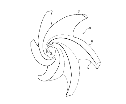
The mixer rotor 10 represented in Figure
~n3~
- 3 -
consists of a series of blades 12 which are wound in a
spiral around a hub 14 which i8 carried by a rotation
spindle, not shown, to rotate in the direction
represented by the arrow in Figure 1. Each blade 12
includes a leading edge 16 which scrapes against a
perforated plate through which the paper pulp is forced.
It is therefore this leading edge 16 which i8 subjected
to the most amount of wear by abrasion in contact with
the solid waste and contamination to be found in the
1 0 pulp .
In order to improve resistance to wear while
maintaining enough ductility to guarantee good ability to
withstand mechanical stresses, the invention proposes
bimetallic or composite blades, the leading edge 16 of
which is formed by an insert with high hardness and good
resistance to wear. Such an insert is represented as 18
in Figure 2. This insert includes a curved elongate body
20, the convex dorsal fac-e 26 of which is intended to
form the leading edge 16 of the blade 12. There is a
thinner rib 22 on the concave ventral face of the body
20, and this extends in the middle region of the body 20.
This rib 22 along its entire length has perforations 24
which pass right through the thickness of the rib 22.
The insert 18 is cast in an appropriate mould. It
is made of martensitic steel and its hardness after
quench and temper is of the order of 50 to 55 Rc. Its
high chromium content gives it good resistance to
corrosion and abrasion.
The inserts 18 intended for the various blades 12
of the rotor are arranged in a mould with shapes which
complement those of the rotor 12 and are fixed
temporarily therein, for example by bonding. The ba~e
alloy 28 i~ then cast to form the rotor 12. This alloy
may be made of stainless steel, for example of the type
UNSJ 91540, for which the hardness after guench and
temper is relatively low, of the order of 25 to 30 Rc.
As this base alloy 28 is poured, it partially
coats the inserts 18, the body 22 of which will form a
large part of the leading edge 16 of each blade, as
~nn3~
_ - 4 -
represented in Figure 3. As this base alloy 28 is being
poured, it more particularly coats the entire rib 22 of
each insert and forms bridges through the ~arious
perforations 24 as represented in Figure 4 in order to
establish a rigid mechanical connection with each insert.
This connection is further strengthened, as the base
alloy cools and shrinks and thus forms a good clinched
connection between the insert and the rest of the blade.
Instead of casting the entire rotor, it is also
possible to cast the various blades 12 separately and
then attach them to the central hub 14 by welding. This
has the advantage, should the blades wear, that the hub,
which is relatively expensive to manufacture owing to the
mach; n~ ng required to be able to mount it on a drive
shaft can then be recovered.