Note: Descriptions are shown in the official language in which they were submitted.
WO 96/09564 PCT/US95/10430
'~~~1~ 4~
~ CYTOLOGICAL SYSTEM AUTOFOCUS INTEGRITY
CHECKING APPARATUS
The present invention relates to a method for
evaluation of autofocus integrity in automated machine
vision instruments. More specifically, in one
embodiment of the invention, the evaluation may be
conducted for an autofocus system to determine
illumination quality, noise floor level, focus filter
frequency response, focus camera modulation transfer
function (MTF), focus camera longitudinal separation,
focus camera lateral and angular alignment, and closed
loop accuracy in an instrument performing automated
cytological analysis.
BACKGROUND OF THE INVENTION
Automated analysis of biological specimens is
typically carried out by a computer controlled system
having an automated microscope with an autofocus
system. Such automated systems require a high degree
of performance and consistency from the autofocus
system. Image processing analyses of biological
specimens use various segmentation algorithms and
morphological operations that depend on consistent
imagery for accurate and repeatable results. The
autofocus system must provide consistent imagery by
providing a suitably high quality focus to yield
images of clinical value. Accordingly, the focus
system must be checked frequently during operation of
such analysis systems to ensure highly consistent and
accurate performance. It is one motivation of this
disclosure to provide techniques and apparatus for
characterizing an autofocus system during operation.
SUMMARY OF THE INVENTION
The present invention provides an automated
method for checking cytological system autofocus
integrity. The automated method includes the steps of
checking focus illumination integrity, checking focus
CA 02200453 2001-04-23
77501-15
2
camera Modulation Transfer Function (MTF), checking focus
camera position integrity, and checking closed loop accuracy.
Checking focus illumination integrity includes checking focus
illumination system integrity, and checking a focus noise floor
level. Checking focus camera position integrity includes
checking focus camera longitudinal separation, and checking
focus camera lateral separation. Checking focus camera
position integrity includes checking focus filter frequency
response.
In summary this invention seeks to provide an
automated method for checking cytological system autofocus
integrity, the automated method comprising the steps of: a)
checking autofocus system illumination quality; b) checking
autofocus system frequency response; c) checking autofocus
system component position quality; and d) checking autofocus
system closed loop accuracy.
Other objects, features and advantages of the present
invention will become apparent to those skilled in the art
through the description of the preferred embodiment, claims and
drawings herein wherein like numerals refer to like elements.
BRIEF DESCRIPTION OF THE DRAWINGS
To illustrate this invention, a preferred embodiment
will be described herein with reference to the accompanying
drawings.
Figures lA and 1B show an automated cytology system
as contemplated by the method and apparatus of the invention.
Figure 2 schematically shows an automated microscope
of the type used in automated cytological system having a
calibration plate mounted on a movable stage.
CA 02200453 2001-04-23
77501-15
2a
Figure 3 shows one example of a calibration and test
target or plate as used in one aspect of the invention.
Figure 4 shows an example of a fiducial marking.
Figure 5 shows a flow diagram of one method of the
invention for checking focus system illumination quality.
Figure 6 shows a flow diagram of one method of the
invention for checking focus noise floor level.
Figure 7 shows a flow diagram of one method of
WO 96/09564 PCT/US95/10430
.- 2200453
- 3 -
the invention for checking focus filter frequency
response.
Figure 8 shows a graph of focus filter response.
Figure 9 shows a flow diagram of one method of
the invention for checking focus camera MTF.
Figure 10 shows a flow diagram of one example of
the method of the invention for performing a focus
camera longitudinal separation test.
Figure 11 shows a flow diagram showing one
example of the method of the invention for checking
focus camera lateral separation.
Figure 12 shows a flow diagram of one example of
a closed loop fiducial focus test in accordance with
the rest of the invention.
Figure 13 is a graph illustrating the
relationship between the passband frequency component
of the signal provided by the camera assembly of
Figure lA and the focus of the camera assembly.
Figure 14 is a more detailed illustrative diagram
of the camera assembly that comprises the subject
invention.
Figure 15 is an illustrative diagram of a circuit
for determining the focus position of the camera
assembly of Figure 14 in accordance with an alternate
focussing procedure.
Figure 16 shows a schematic view of a typical
cell.
Figure 17 shows a process for converting physical
cell size into electrical band width.
Figure 18 graphically illustrates a time vary
voltage of a dark nucleus.
Figure 19 shows an inverted pulse representing a
square function.
Figures 20 and 21 show a Fourier transformation
for a square function as employed in one aspect of the
invention.
WO 96!09564 PG"f/US95/10430
22Q0453
- 4
y ~,
x . ;.
Figure 22 illustrates a filter response sensitive
to objects of interest, such as cell nuclei as
employed in one embodiment of the invention.
Figure 23 shows an example of a modulation
transfer function as employed in one embodiment of the
invention.
Figures 24A, 24B, 24C and 24D show bar patterns
of progressively increasing spatial frequency and an
intensity profile of those bar patterns in an image
plane.
Figure 25A shows a square wave plot for a
theoretically perfect square wave.
Figure 25B shows the Fourier transform of a
perfect square wave.
Figure 26 shows one example of an FFT foldback
for MTF determination beyond the detector sampling
frequency.
DETAILED DESCRIPTION OF TF~E PREFERRED EMBODIMENT
This invention consists of a suite of tests and
a parameter monitoring method for characterizing focus
illumination quality, noise floor level, focus filter
frequency response, focus camera modulation transfer
function, focus camera longitudinal separation, focus
camera lateral and angular alignment and closed loop
accuracy of an autofocus system as used in an
automated machine vision instrument. The examples of
tests discussed herein refer specifically by way of
example to a system with a pulsed arc lamp and CCD
imaging devices for primary and at least two autofocus
cameras. The focus apparatus in a preferred
embodiment uses an above and below focus camera
frequency balancing method to determine the magnitude
and direction to move to best focus . In addition, the
images are passed through a set of focus filters to
optimize performance for biological nuclear detail.
The specifics of one example of a focus system are
CA 02200453 2001-04-23
77501-15
outlined in "Method and Apparatus For Rapid Capture of Focused
Microscopic Images" by Jon Hayenga, et al., discussed further
hereinbelow. However, the invention is not considered to be
limited to the specific examples set forth herein. The
5 concepts contained herein may be employed to other focus
systems using continuous arc lamps, filament lamps, LASER
sources, tube cameras, TDI sensors, PIN diodes and
photomultiplier tubes.
In a presently preferred embodiment of the invention,
the system disclosed herein is used in a system for analyzing
cervical pap smears, such as that shown and disclosed in United
States Patent 5,787,188 issued July 28, 1998 entitled "Method
for Identifying Normal Biomedical Specimens", by Alan C.
Nelson, et al.; U.S. Patent 5,528,703 issued June 18, 1996
entitled "Method for Identifying Objects Using Data Processing
Techniques", by S. James Lee, et al.; U.S. Patent No.
5,315,700, entitled "Method and Apparatus for Rapidly
Processing Data Sequences", by Richard S. Johnston; U.S. Patent
5,361,140 issued November l, 1994 entitled "Method and
Apparatus for Dynamic Correction of Microscopic Image Signals",
by Jon W. Hayenga, et al.; and U.S. Patent 5,912,699 Hayenga,
et al. issued June 15, 1999 entitled "Method and Apparatus for
Rapid Capture of Focused Microscopic Images" to Hayenga, et al.
The present invention is also related to biological
and cytological systems as described in the following patents
including United States Patent 5,715,326 issued Feb. 03, 1998,
to Ortyn et al., entitled "Cytological System Illumination
Integrity Checking Apparatus and Method," United States Patent
No. 5,581,631, issued Dec. 03, 1996 to Ortyn et al., entitled
"Cytological System Image Collection Integrity Checking
Apparatus," United States Patent No. 5,557,097, issued
CA 02200453 2001-04-23
77501-15
6
Sept. 17, 1996, to Ortyn et al., entitled "Cytological System
Autofocus Integrity Checking Apparatus," United States Patent
No. 5,499,097, issued March 12, 1996 to Ortyn et al., entitled
"Automated Cytology System Position Integrity Checking Method
and Apparatus," United States Patent No. 5,875,258, issued
February 23, 1999, to Ortyn et al., entitled "Biological
Specimen Analysis System Processing Integrity Checking
Apparatus."
The present invention is also related to biological
and cytological systems as described in the following patents
including United States Patent 5,757,954 issued May 26, 1998
entitled, "Field Prioritization-Apparatus and Method," United
States Patent 5,978,498 issued November 2, 1999, entitled
"Apparatus for Automated Identification of Cell Groupings on a
Biological Specimen," United States Patent 5,987,158 issued
November 16, 1999 to Meyer et al., entitled "Apparatus for
Automated Identification of Thick Cell Groupings on a
Biological Specimen," United States Patent 5,828,776 to Lee et
al. issued October 27, 1998 entitled "Apparatus for
Identification and Integration of Multiple Cell Patterns,"
United States Patent 5,627,908 to Lee, et al. issued May 6,
1997 entitled "A Method for Cytological System Dynamic
Normalization," United States Patent 5,638,459 to Rosenlof, et
al. issued June 10, 1997 entitled "Method and Apparatus for
Detecting a Microscope Slide Coverslip," United States Patent
5,566,249 to Rosenlof, et al. issued October 15, 1996 entitled
"Apparatus for Detecting Bubbles in Coverslip Adhesive," United
States Patent 5,933,519 to Lee, et al. issued August 3, 1999
entitled "Cytological Slide Scoring Apparatus," United States
Patent 5,692,066 to Lee, et al. issued November 25, 1997
entitled "Method and Apparatus for Image Plane Modulation
Pattern Recognition," United States Patent 5,978,497 to Lee, et
al. issued November 2, 1999 entitled "Apparatus for the
CA 02200453 2001-04-23
77501-15
7
Identification of Free-Lying Cells," United States Patent
5,740,269 to Oh, et al. issued April 14, 1998 entitled "A
Method and Apparatus for Robust Biological Specimen
Classification," United States Patent 5,715,327 to Wilhelm, et
al. issued February 3, 1998 entitled "Method and Apparatus for
Detection of Unsuitable Conditions for Automated Cytology
Scoring."
Now refer to Figures lA and 1B which show a schematic
diagram of one embodiment of the apparatus of the invention for
checking system autofocus integrity for an automated machine
vision system. While the method and apparatus of the invention
will be discussed in terms of an example herein related to an
automated cytology apparatus, it will be understood that the
invention is not so limited. The features and principles of
the invention may be applied to check urine analysis processes,
semiconductor process defects, liquid crystal devices and other
types of processing systems employing, for example, continuous
arc lamps, filament lamps, laser sources, tube cameras, PIN
diodes and photomultiplier tubes.
The apparatus of the invention comprises an imaging
system 502, a motion control system 504, an image processing
system 536, a central processing system 540, and a workstation
542. The imaging system 502 is comprised of an illuminator
508, imaging optics 510, a CCD camera 512, an illumination
sensor 514 and an image capture and focus system 516. The
image capture and focus system 516 provides video timing data
to the CCD cameras 512, the CCD cameras 512 provide images
comprising scan lines to the image capture and focus system
516. An illumination sensor intensity is provided to the image
capture and focus system 516 where an illumination sensor 514
receives the sample of the image from the optics 510. In one
embodiment of the invention, the optics may further comprise an
CA 02200453 2001-04-23
77501-15
8
automated microscope. The illuminator 508 provides
illumination of a slide. The image capture and focus system
516 provides data to a VME bus 538. The VME bus distributes
the data to an image processing system 536. The image
processing system 536 is comprised of field-of-view processors
568. The images are sent along the image bus 564 from the
image capture and focus system 516. A central processor 540
controls the operation of the invention through the VME bus
538. In one embodiment the central processor 562 comprises a
Motorola 68030 CPU. The motion controller 504 is comprised of
a tray handler 518, a microscope stage controller 520, a
microscope turret controller 522, and a calibration slide 524.
The motor drivers 526 position the slide under the optics. A
bar code reader 528 reads a barcode located on the slide 524.
A touch sensor 530 determines whether a slide is under the
microscope objectives, and a door interlock 532 prevents
operation in case the doors are open. Motion controller 534
controls the motor drivers 526 in response to the central
processor 540. An Ethernet (TM) communication system 560
communicates to a workstation 542 to provide control of the
system. A hard disk 544 is controlled by workstation processor
550. In one embodiment, workstation 542 may comprise a Sun
SPARC Classic (TM) workstation. A tape drive 546 is connected
to the workstation processor 550 as well as a modem 548, a
monitor 552, a keyboard 554, and a mouse pointing device 556.
A printer 558 is connected to the Ethernet (TM) network 560.
During system focus integrity checking, the central
computer 540, running a real time operating system, controls
the automated microscope and the processor to acquire and
digitize images from the microscope. The flatness of the slide
CA 02200453 2001-04-23
77501-15
8a
may be checked, for example, by contacting the four corners of
the slide using a computer controlled touch sensor. The
computer 540 also controls the microscope stage to position the
specimen under the microscope objective, and from one to 15
field of view (FOV) processors 568 which receive images under
control of the computer 540.
It is to be understood that the various processes
described hereinabove with respect to checking illumination
quality, noise floor level, focus filter frequency response,
focus camera modulation transfer function, focus camera
longitudinal separation, focus camera lateral and angular
alignment, and closed loop accuracy in an instrument performing
automated cytological analysis may be implemented in software
suitable for running on a digital processor or computer. The
software may be embedded, for example, in the central processor
540.
Referring now to Figure 2, there shown is placement
of a calibration and test target 1 into an optical path of an
automated microscope 3 having a turret 22. The calibration and
test target may be mounted on a stage 521 substantially in a
horizontal X,Y plane which intersects the optical path. The
stage 521 is movable in the X,Y plane as well as along
WO 96/09564 PCT/iJS95/10430
_ g _
a Z axis which is perpendicular to the X,Y plane and
which is parallel to the optical axis of the automated
microscope. The turret 22 may comprise multiple
objective lenses as is well known in the art. The
microscope turret control 522 provides signals in a
well known manner for positioning a selected objective
lens into position for viewing a slide, for example.
Referring now to Figure 3 one example of a
calibration and test target is shown. Several of the
processes employed by the present invention require a
calibration and target plate. In the case of a
transmission microscope, the calibration and test
target 1 may comprise a piece of glass approximately
1.45 mm thick. The calibration and test target
advantageously comprises specified clear areas 34 and
image primitives such as horizontal and vertical bar
targets 36. The clear area simulates a microscope
slide. The clear areas' are used herein for
illumination and noise quality tests. The image
primitives are used for frequency response and
position testing. Other types of calibration
markings, such as fiducial markings, may also be used.
Figure 4 shows an example of a fiducial marking. Such
calibration and test target plates may be used for
most transmission microscopes to simulate the optical
path difference effects introduced by the substrate,
coverslip and specimen media. In some embodiments of
the invention, the calibration and test target may be
advantageously mounted onto a conventional cantilever
arm for ease of placement into the optical path in
proximity to a position where a specimen would
normally be positioned.
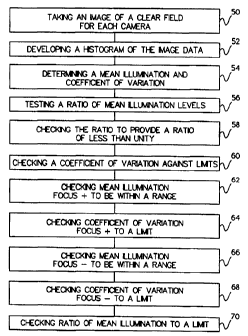
Focus System Illumination Quality
Referring now to Figure 5, Figure 5 shows a flow
diagram of the method of the invention for checking
focus system illumination quality. Proper
WO 96/09564 PCT/US95/10430
220~~53 _~ w w ~' ~~~ ~v
- 1~ -
illumination at the focus cameras is needed for
accurate focus of an automated biological specimen
analysis system. An above and below autofocus method
often determines the signal strength for each camera
used in such a system and attempts to balance those
signals . Such methods use at least two focus cameras .
If the illumination level is different at each camera,
there may be a discrepancy in signal strength even
though the locus of the image presented to each camera
may be identical. The invention provides a focus
illumination test to be performed on each focus camera
to check the illumination quality. The focus
illumination test helps ensure that a signal presented
to each camera is not influenced by any defect in
illumination. At step 5d, an image is taken of a
clear field for each camera and, at step 52, a
histogram is developed similar to that shown in Table
1. This histogram provides intensity values of the
entire field for a focus and camera. From the
histogram the mean illumination and coefficient of
variation of the intensity of the field is determined
for each camera at step 54.
WO 96109564
2 2 0 0 4 ~ ~ pCT~S95/10430
- 11 -
Table 1
Intensity Histogram of Entire Field For
Focus + Camera
Int Int Int Int Int Int Int Int #
# # # # # # #
0: 32: 64: 96: 128:0 160:0 192:0 224: 2
0 0 0 0
1: 33: 65: 97: 129:0 161:0 193:0 225: 7
0 0 0 0
2: 34: 66: 98: 130:0 162:0 194:0 226: 213
0 0 0 0
3: 35: 67: 99: 131:0 163:0 195:0 227:1424
0 0 0 0
4: 36: 68: 100:0 132:0 164:0 196:0 228:7803
0 0 0
5: 37: 69: 101:0 133:0 165:0 197:0 229:47942
0 0 0
6: 38: 70: 102:0 134:0 166:0 198:0 230:60366
0 0 0
7: 39: 71: 103:0 135:0 167:0 199:0 231:74350
0 0 0
8: 40: 72: 104:0 136:0 168:0 200:0 232:51837
0 0 0
9: 41: 73: 105: 137: 169: 201: 233:15630
0 0 0 0 0 0 0
10: 42: 74: 106:0 138:0 170:0 202:0 234:2231
0 0 0
11: 43: 75: 107:0 139:0 171:0 203:0 235: 317
0 0 0
12: 44: 76: 108: 140: 172: 204: 236: 22
0 0 0 0 0 0 0
13: 45: 77: 109:0 141:0 173:0 205:0 237: 0
0 0 0
14: 46: 78: 110:0 142:0 174:0 206:0 238: 0
0 0 0
2 0 15: 47: 79: 111: 143: 175: 207: 239: 0
0 0 0 0 0 0 0
16: 48: 80: 112:0 144:0 176:0 208:0 240: 0
0 0 0
17: 49: 81: 113:0 145:0 177:0 209:0 241: 0
0 0 0
18: 50: 82: 114:0 146:0 178:0 210:0 242: 0
0 0 0
19: 51: 83: 115:0 147:0 179:0 211:0 243: 0
0 0 0
2 5 20: 52: 84: 116: 148: 180: 212: 244: 0
0 0 0 0 0 0 0
21: 53: 85: 117:0 149:0 181:0 213:0 245: 0
0 0 0
22: 54: 86: 118:0 150:0 182:0 214:0 246: 0
0 0 0
23: 55: 87: 119:0 151:0 183:0 215:0 247: 0
0 0 0
24: 56: 88: 120:0 152:0 184:0 216:0 248: 0
0 0 0
3 0 25: 57: 89: 121: 153: 185: 217: 249: 0
0 0 0 0 0 0 0
26: 58: 90: 122:0 154:0 186:0 218:0 250: 0
0 0 0
27: 59: 91: 123:0 155:0 187:0 219:0 251: 0
0 0 0
28: 60: 92: 124:0 156:0 188:0 220:0 252: 0
0 0 0
29: 61: 93: 125:0 157:0 189:0 221:0 253: 0
0 0 0
3 5 30: 62: 94: 126: 158: 190: 222: 254: 0
0 0 0 0 0 0 0
31: 63: 95: 127:0 159:0 191:0 223:0 255: 0
0 0 0
WO 96/09564 ~ PCT/US95/10430
- 12 -
Table 2
Intensity Histogram of Entire Field For
Focus (-) Camera
Int Int Int Int Int Int Int Int #
# # # # # # #
0: 32: 64: 96: 128: 160: 192: 224: 0
0 0 0 0 0 0 0
1: 33: 65: 97: 129:0 161:0 193:0 225: 0
0 0 0 0
2: 34: 66: 98: 130:0 162:0 194:0 226: 0
0 0 0 0
3: 35: 67: 99: 131:0 163:0 195:0 227: 0
0 0 0 0
4: 36: 68: 100:0 132:0 164:0 196:0 228: 1
0 0 0
5: 37: 69: 101:0 133:0 165:0 197:0 229: 0
0 0 0
6: 38: 70: 102:0 134:0 166:0 198:0 230: 214
0 0 0
7: 39: 71: 103:0 135:0 167:0 199:0 231: 404
0 0 0
8: 40: 72: 104:0 136:0 168:0 200:0 232:6823
0 0 0
9: 41: 73: 105:0 137:0 169:0 201:0 233:8942
0 0 0
10: 42: 74: 106:0 138:0 170:0 202:0 234:62366
0 0 0
11: 43: 75: 107:0 139:0 171:0 203:0 235:62350
0 0 0
12: 44: 76: 108:0 140:0 172:0 204:0 236:61837
0 0 0
13: 45: 77: 109:0 141:0 173:0 205:0 237:16630
0 0 0
14: 46: 78: 110:0 142:0 174:0 206:0 238:1231
0 0 0
2 0 15: 47: 79: 111: 143: 175: 207: 239: 217
0 0 0 0 0 0 0
16: 48: 80: 112:0 144:0 176:0 208:0 240: 122
0 0 0
17: 49: 81: 113:0 145:0 177:0 209:0 241: 0
0 0 0
18: 50: 82: 114:0 146:0 178:0 210:0 242: 0
0 0 0
19: 51: 83: 115:0 147:0 179:0 211:0 243: 0
0 0 0
2 5 20: 52: 84: 116: 148: 180: 212: 244: 0
0 0 0 0 0 0 0
21: 53: 85: 117:0 149:0 181:0 213:0 245: 0
0 0 0
22: 54: 86: 118:0 150:0 182:0 214:0 246: 0
0 0 0
23: 55: 87: 119:0 151:0 183:0 215:0 247: 0
0 0 0
24: 56: 88: 120:0 152:0 184:0 216:0 248: 0
0 0 0
3 0 25: 57: 89: 121: 153: 185: 217: 249: 0
0 0 0 0 0 0 0
26: 58: 90: 122:0 154:0 186:0 218:0 250: 0
0 0 0
27: 59: 91: 123:0 155:0 187:0 219:0 251: 0
0 0 0
28: 60: 92: 124:0 156:0 188:0 220:0 252: 0
0 0 0
29: 61: 93: 125:0 157:0 189:0 221:0 253: 0
0 0 0
3 5 30: 62: 94: 126: 158: 190: 222: 254: 0
0 0 0 0 0 0 0
31: 63: 95: 127:0 159:0 191:0 223:0 255: 0
0 0 0
R'O 96/09564 PCT/US95/10430
zzoo~~3
- 13 -
The ratio of mean illumination levels is tested
along with the absolute value of the means at step 56.
The ratio is checked and inverted if necessary to
provide a ratio of less than unity. This allows for
one limit to be set for the ratio. The coefficient of
variation for each camera is also checked against
limits at step 60. Limits are seen below in Table 3.
At step 62, the mean illumination focus+ is
checked to be within a certain tolerance range. At
step 64, the coefficient of variation of the focus+
camera is checked against a predetermined limit. At
step 66, the mean illumination of the focus plus
camera is checked to be within a predetermined range
of values. At step 68 the coefficient of variation of
the focus+ camera is checked against a predetermined
limit. Similarly, at step 70, the ratio of beam
illumination is checked against a predetermined limit.
Table 3
Parameter Results and Limits Comparison for
Static Field Uniformity
Parameter Description Actual Value Limits
Mean Illumination Focus (+) 231 220 < x < 250
Coef f icient of variation
Focus (+) 0.6% < 1.0 %
Mean Illumination
Focus (+) 235 220 < x < 250
Coefficient of variation
Focus (+) 0.7% < 1.0%
Ratio of Mean Illumination 0.98 > 0.97
Focus Noise Floor Level
Now referring to Figure 6, a flow diagram of the
invention for checking focus noise floor level is
shown. The above and below focus method being tested
in accordance with the invention uses focus filters
WO 96/09564 PCT/US95/10430
22pp~53 - 14 -
for each camera as shown in Figure 15. The focus
filters are electronic filters which optimize signals
delivered from the cameras for focus processing by
filtering out objects that do not have the
characteristic frequency content of cellular nuclei.
Filtering techniques are described in more detail
below. Debris in the focus paths and electronic noise
may generate erroneous focus projections.
Theoretically, the response of the focus filters
should be zero over a uniformly illuminated clear
field of view. In actuality, however, the response of
the filters to this type of stimulus is rarely, if
ever, zero. Electronic noise, debris in the focus
path, and focus filter inefficiencies can and do
result in some response at the output. This response
is referred to as the "focus noise floor level."
Specifically, the focus noise floor level is the
response of the focus filters to a uniformly
illuminated clear field. One aspect of the invention
provides a test for measuring the amplitude of filter
response under this condition. In addition, since the
above and below focus method employed generates a
focus filter data point for each active line in the
video timing, in one example, a total of 512 focus
noise floor levels are captured and analyzed for the
focus plus and focus minus response. A focus noise
floor test is performed on each focus camera to ensure
proper operation.
At step 72, a selected objective is positioned
over the nominal clear area of the calibration plate
with, for example, a 20x magnification selected. An
image is acquired at step 74 and at step 76 noise
scores for each line of the plus and minus focus
filters are acquired. Data acquired from each channel
is processed to determine the maximum noise values for
each channel at step 78. The maximum score for each
WO 96109564 2 ~ 0 0 ~ 5 ~ PCT/US95/10430
- 15 -
filter is then recorded as the focus noise floor at
step 80. At step 82 the focus plus noise floor is
checked against a predetermined limit. The focus
minus noise floor is also checked at step 84.
Examples of focus noise floor limits are shown below.
Limits
Focus + noise floor: < 10 counts
Focus - noise floor: < 10 counts
Focus Filter Frequency Response
Now referring to Figure 7, a schematic flow
diagram of one method for checking focus filter
frequency response is shown. The electronic band-pass
filters discussed below, utilized by the focus
channels are optimized for maximum sensitivity in the
frequency range characteristic to that of cellular
nuclei. To determine the focus projection of "best
clinical value" these filters must perform
appropriately in both the stop and pass bands. The
bandpass is chosen to heavily weigh frequencies which
are generated by cellular nuclei when imaged at a
defocus of about four microns. Four microns is, in
one embodiment, the nominal separation of the focus
and primary cameras. Poorly adjusted, or
malfunctioning focus filters may severely skew the
focus projection value. It is necessary, therefore,
to accurately quantify the performance of the filters
to ensure proper operation of the focus subsystem.
The focus filter frequency response test of the
invention provides the means for evaluating filter
efficacy by evaluating its output response to that of
a known test pattern. It is advantageous to perform
this test prior to running a batch of slides for
analysis.
At step 86, a Harming windowed swept sine wave is
electronically generated from 50 kHz to 2.2 MHz. in
WO 96/09564 PCTIUS95/10430
.:
~~~~~4~3 .:,.~:i
- 16 -
the ICF image buffer according to the expression:
I (X;) - G[ (1 + sin (2~rTXi*f+~) * {1 + Gh (sin (~r
Xi/ (NoPixels-1) ) } ] + 0.5
Where:
I(Xi) - The intensity or amplitude of the
ith pixel.
X; - The horizontal position index of
the ith pixel or sample. From 0
through 511 samples.
~ - The phase term for each sample.
Typically 0 radians.
G - Intensity gain factor.
Gh - Harming gain factor.
NoPixels - Total number of pixels or samples.
At step 88 it is indicated that the intensity of
each sample, I(xi) is modulated according to the
expression given above. At step 90, the image formed
by the collection of each video line then serves as
the input stimulus to the focus filters. This
pattern, contained in the image capture buffer (ICF)
516 as digital values, is then reconstructed into an
analog waveform by routing it through an on board D/A
converter at step 92. The analog waveform is then
routed to the input of the focus plus and minus
filters providing them necessary stimulus for
characterizing the overall output response at step
94.
Response limits have been empirically determined
for a machine manufactured by NeoPath, Inc. of
Bellevue, Washington, U.S.A. called the AP300 System.
The empirically derived limits represent the maximum
and minimum allowable output variation for the
filters. To ensure proper operation of the Focus
System, the AP300 machine evaluates the response of
the focus filters when initially processing of each
WO 96!09564 PCT/US95/10430
- 1~ -
new tray of slides. Figure 8 illustrates the filter
response envelope, the upper and lower curves, 100 and
102 respectively, represent the maximum and minimum
limits. The middle curve 104 represents a typical
response for a normally functioning filter. Table 5,
contains an example of limits used for evaluating
filter response. Bin 0, corresponds to the starting
frequency of the test pattern (50Khz). Bin 255
corresponds to the ending frequency of the test
pattern (2.2Mhz) .
WO 96/09564 PCT/US95/10430
Y.
220453
Table 5
Intensity Histogram of Entire Field For
Focus + Camera
BinMin Max Bin Min Max Bin Min Max Bin Min Max
0 0 12 64 110 133 128 0 34 192 0 13
1 0 12 65 110 133 129 0 34 193 0 13
2 0 12 66 110 133 130 0 33 194 0 13
3 0 12 67 110 133 131 0 33 195 0 13
4 0 12 68 110 133 132 0 32 196 0 13
1 0 5 0 12 69 110 133 133 0 32 197 0 13
6 0 12 70 110 133 134 0 31 198 0 13
7 0 12 71 110 133 135 0 31 199 0 13
8 0 12 72 110 133 136 0 30 200 0 13
9 0 12 73 108 131 137 0 30 201 0 13
1 5 10 0 12 74 106 129 138 0 29 202 0 13
11 0 12 75 104 127 139 0 29 203 0 13
12 0 12 76 102 125 140 0 28 204 0 13
13 0 12 77 100 123 141 0 28 205 0 13
14 0 12 78 98 121 142 0 27 206 0 13
2 0 15 0 12 79 96 119 143 0 27 207 0 13
16 0 12 80 94 117 144 0 26 208 0 13
17 0 12 81 92 115 145 0 25 209 0 13
18 0 12 82 90 113 146 0 25 210 0 13
19 0 12 83 88 111 147 0 24 211 0 13
2 5 20 0 12 84 86 109 148 0 24 212 0 13
21 0 12 85 84 107 149 0 23 213 0 13
22 0 12 86 82 105 150 0 23 214 0 13
23 0 12 87 80 103 '1510 22 215 0 13
24 0 12 88 78 101 152 0 22 216 0 13
3 0 25 0 12 89 76 99 153 0 21 217 0 13
26 0 12 90 74 97 154 0 21 218 0 13
27 0 18 91 72 95 155 0 20 219 0 13
28 0 23 92 70 93 156 0 20 220 0 13
29 0 29 93 68 91 157 0 19 221 0 13
3 5 30 0 34 94 66 89 158 0 19 222 0 13
31 0 40 95 64 87 159 0 18 223 0 13
32 0 45 96 62 85 160 0 18 224 0 13
33 0 51 97 60 83 161 0 17 225 0 13
34 0 56 98 58 81 162 0 17 226 0 13
4 0 35 0 62 99 56 79 163 0 16 227 0 13
36 0 67 100 54 77 164 0 16 228 0 13
37 0 73 101 52 75 165 0 15 229 0 13
38 0 78 102 50 73 166 0 15 230 0 13
39 0 84 103 48 71 167 0 14 231 0 13
WO 96/09564 ~ PCT/US95/10430
- 19 -
Table 5 - Continued
Intensity Histogram of Entire Field For
Focus + Camera
Bin Min Max Bin Min Max Bin Min Max Bin Min Max
40 43 89 104 46 69 168 0 14 232 0 13
41 49 95 105 44 67 169 0 13 233 0 13
42 55 100 106 42 65 170 0 13 234 0 13
43 61 106 107 40 63 171 0 13 235 0 13
44 67 111 108 38 61 172 0 13 236 0 13
1 0 45 73 117 109 36 59 173 0 13 237 0 13
46 79 122 110 34 57 174 0 13 238 0 13
47 86 128 111 32 55 175 0 13 239 0 13
48 92 133 112 30 53 176 0 13 240 0 13
49 98 133 113 28 51 177 0 13 241 0 13
1 5 50 104 133 114 26 49 178 0 13 242 0 13
51 109 133 115 24 47 179 0 13 243 0 13
52 110 133 116 22 45 180 0 13 244 0 13
53 110 133 117 20 43 181 0 13 245 0 13
54 110 133 118 18 41 182 0 13 246 0 13
2 0 55 110 133 119 16 39 183 0 13 247 0 13
56 110 133 120 14 38 184 0 13 248 0 13
57 110 133 121 12 38 185 0 13 249 0 13
58 110 133 122 10 37 186 0 13 250 0 13
59 110 133 123 8 37 187 0 13 251 0 13
2 5 60 110 133 124 6 36 188 0 13 252 0 13
61 110 133 125 4 36 189 0 13 253 0 13
62 110 133 126 2 35 190 0 13 254 0 13
63 110 133 127 0 35 191 0 13 255 0 13
If the focus filter frequency response test
30 fails, either in pass or stop bands, the failure is
logged and system integrity checks are advantageously
rerun. Pass bands and stop bands are specific
frequencies which depend upon the system being tested.
Focus filter response may comprise a non calibratable
35 subsystem and as such may not be adjusted by the
system. In one example, a system level integrity test
will attempt to measure the systems response a maximum
of 5 times. If the filter response does not pass
during these attempts the system is halted.
40 Focus Camera Modulation Transfer Function
Now referring to Figure 9, a flow diagram of one
example of the invention for checking focus camera MTF
is shown. The focus system relies on several
CA 02200453 2001-04-23
77501-15
components. In this example, the optics deliver images to the
focus cameras at a specified spacing, cameras convert the image
into an electronic signal, and the ICF converts the electronic
signal into an estimate of the focus of the image projected to
5 the primary camera in the camera head assembly. This test
measures a focus camera's ability to represent contrast and
fine image detail in its electronic signal.
One method of performing a Modulation Transfer
Function test is discussed hereinbelow. The ability of the
10 focus cameras to represent the image accurately with their
electronic signal is important to a properly operating focus
system and must be checked periodically to insure acceptable
operation.
This test may be used to insure operation for a focus
15 camera component in a focus system such as the one described in
United States Patent 5,912,699 Hayenga, et al. issued June
15, 1999 entitled "Method and Apparatus for Rapid Capture of
Focused Microscopic Images" to Hayenga, et al.
Like the primary focus filters, the focus camera
20 modulation transfer function is critical to projecting the
focus of best clinical value. An MTF test is conducted for
each focus camera to ensure proper operation.
At step 111 the 50 lp/mm vertical bar target is
positioned under the objective. In one example, the vertical
bar target may be a bar target of 50 lp/mm. At step 112, the
focus+ channel is routed to the ICF image buffer. At step 114,
an MTF focus pan is performed to find the optimal focus
position and the image of best focus is retained. At step 116,
a horizontal MTF computation is performed on 32 rows at the
center of the image to measure the response of the focus+
camera. The same procedure is repeated for the focus- camera.
CA 02200453 2001-04-23
77501-15
21
Given the manufacturer's specification for the camera
and the optical transfer function of the preferred embodiment
disclosed in United States Patent 5,912,699 Hayenga, et al.
issued June 15, 1999 entitled "Method and Apparatus for Rapid
Capture of Focused Microscopic Images" to Hayenga, et al.
Tables 6 and 7 list the focus+ and focus- camera frequency
response limits. Measurements that yield lower results than
these limits indicate a malfunctioning or substandard camera or
optical path.
Table 6
Focus+ Camera MTF
Frequency Limits Minimum MTF
Minimum Maximum Center
0.0 0.0 0.45
47.5 52.5 0.84
142.5 157.5 0.73
237.5 262.5 0.54
332.5 367.5 0.41
WO 96/09564 . , PCT/US95/10430
,r ~ ; ,
~, ., a
a . 4,.~ fi
X20045.
- 22 -
Table 7
Focus- Camera MTF
Frequency Limits Minimum MTF
Minimum Maximum Center
0.0 0.0 0.45
47.5 52.5 0.84
142.5 157.5 0.73
237.5 262.5 0.54
332.5 367.5 0.41
Focus Camera Longitudinal Separation Test
Referring now to Figure 10, a flow diagram for
one example of a focus camera longitudinal separation
test is shown. In a focus system described in
Hayenga, et. al., focus cameras are spaced above and
below the optimal image plane of the objective. The
z-separation between the focus and primary cameras
directly affects the focus projection. The z-
separation as used refers to the separation of focus
positions between the focus camera as along the
optical axis. The focus camera longitudinal position
test is conducted to ensure that the camera
separations are within limits.
At step 120, a z-pan is performed over the 50
lp/mm vertical bar target for the primary camera and
each focus camera. The position of optimal focus is
recorded at step 122 and the difference between the
focus cameras and primary camera is taken to determine
the focus separation at step 124. Because of the
extremely small dimensions being measured at 20x, for
example, the measurement is performed at lower
magnification where the effective separation of the
focal planes is much larger. This serves two
purposes, first the positioning and step size errors
WO 96!09564 PCT/US95/10430
as ,
23
at 20x may be a significant percentage of the
measurement. Second, the depth of field of the
objective at 20x makes any tilt of target a
significant contributor to the uncertainty of the
estimate of the optimal focus position. Using a lower
magnification lens makes both the separation and tilt
factors much less significant in the measurement
allowing an effective improvement in the separation
measurement. The Z-separation at a lower
magnification is increased by the ratio of the square
of the relative magnifications. At steps 126 and 128
the focus+ separation and focus- separation are
checked respectively. One example of tolerance ranges
for focus separation is shown below.
Limits
Focus+ separation: 3500 < x < 4500 nm
Focus- separation: -7000 < x <- 6000 nm
Failing the focus separation test preferably
invalidates the results of a previously processed tray
of slides.
Focus Camera Lateral Separation Test
Now referring to Figure 11, one example of a
focus camera lateral separation test is shown in flow
diagram form. A focus projection score, computed as
described in further detail below may be derived, in
part, by "balancing" the frequency content, of the
focus plus and focus minus cameras. It is desirable,
therefore, to image the same field position at both
focus channels. Lateral misalignment in x or y
between channels may result in a different
presentation of the field to each camera. Cellular
data imaged in one channel may not be imaged at all in
the other channel. Mis-positioning will potentially
cause an imbalance in the overall frequency content of
the images presented to each focus camera. A signal
imbalance may ultimately skew the focus projection
WO 96/09564 PCT/US95/10430
s:1
- 24 -
away from optimal focus. In addition, focus line
scores, used in determining the focus projection
value, are qualified in pairs before they are included
into the computation for focus projection. A score
from the plus focus camera is combined with a score
generated by the corresponding line from the minus
focus camera. This qualification technique assumes
that the focus line pairs have been exposed to the
same region in the image. Severe lateral displacement
in y could result in focus score comparisons for
different areas of the image. Rotational, or angular
misalignment between the focus channels may also
result in erroneous focus projection scores for the
same reasons mentioned above. It is therefore
necessary to adjust and periodically measure these
parameters to help ensure proper focus system
operation. The focus camera lateral separation test
measures these parameters and may advantageously be
run prior to processing each tray of slides.
At step 130, a 0,0 fiducial pattern or primitive
is positioned under a 20x objective. Alternately, the
focus+ and focus- video channels may be routed to the
ICF image buffer. A z-pan focus is performed under
control of the FOV computers on the target at step
132. A z-pan focus refers to a focusing procedure in
which a sample is scanned in the Z axis, that is,
along the optical axis, preferably through the focal
plane of the optical system. At predetermined
increments during the scan, images are acquired by a
detector. A plurality of images are processed to
determine a feature, or features, related to the focus
of each individual image. The feature or combination
of features may be, for example, the slope of edge
profiles in the image, or, the spatial frequency
content of the image, or some other suitable feature.
Typically, a plot of the feature or features is
WO 96109564 PCT/US95/10430
._ 220053
- 25 -
generated and an optimal position is determined. The
optimal position indicates the best focus position for
the image.
For each z-pan, the image of best focus is
captured and saved for later analysis at step 134.
The images captured from each channel are then
processed to determine the extent of any lateral (that
is, x and y offsets) or angular offsets between
cameras at steps 138, 140 and 142 respectively. The
table immediately below shows examples of test limits
for the focus camera lateral separation test.
X-axis lateral error: < + 67 microns
Y-axis lateral error: < + 67 microns
Angular error: < ~ 0.01 radians
Failing the lateral separation test preferably
invalidates the results of a previously processed tray
of slides.
Closed Loop Accuracy Test
Referring now to Figure 12, a flow diagram of one
example of a closed loop accuracy test is shown. The
closed loop accuracy test verifies that the focus
achieved by the above and below focus camera method is
consistent with the focus achieved using a z-pan focus
method. In this case the z-pan is performed using the
primary camera in the preferred embodiment of this
system. Although all the focus quality tests are
important factors in developing an accurate focus
projection, an overall closed loop test is required to
ensure the system is operating correctly.
At step 144, a z-pan focus is performed on the
0,0 fiducial using the primary camera.
Simultaneously, as images are acquired on the primary
camera the autofocus system of the instrument is also
developing focus projections according to the
CA 02200453 2001-04-23
77501-15
26
alternate focusing method taught by Hayenga et al. The best
focus for each of the two focusing techniques is determined.
The difference in the two best focus positions is recorded at
step 148. At step 150 a Z difference is checked against a
predetermined tolerance as for example, Z difference:
1000 < x < 3000nm.
The purpose of the autofocus system in the preferred
embodiment is to provide a real time computation determining
the location of best focus. The real time best focus location
can be determined with a single flash of the lamp (i.e. real
time), as the image of the field of interest is captured by the
primary camera and two focus cameras simultaneously. However,
the absolute position of best focus must be compared to a
standard focus. The z-pan method provides a standard of
comparison. Therefore, both methods of focus are compared on a
test target. Although the tests outlined previously in this
disclosure help to qualify the focus system, this test provides
for a final redundant check to ensure the system is operating
properly.
Failing may result in invalidating the results of the
previously processed tray of slides.
In order to promote further understanding of the
invention, one example of a method as taught by Hayenga et al.
and employed by the invention for focusing will now be further
described. As described above with reference to Figures lA, 1B
and Figure 2, the motion controller 504 includes a stage for
receiving the slide 1 and is responsive to a slide scan signal,
received from a processor 540, for moving the stage in a slide
plane represented by X and Y directions. In the illustrative
diagram of Figures lA, 1B and Figure 2, the X and Y directions
are located in the plane that is perpendicular to an
WO 96/09564 PCT/US95/10430
220043
2~ _
optical path intermediate the slide 1 and the
condenser 402. The motion controller 504 is further
responsive to a slide focus signal for moving the
slide 1 in a direction normal to the slide plane,
along the optical path 110, for focusing the camera
upon the slide 1. The motion controller 504 is
constructed to provide a position signal to the
processor 540 wherein the position signal is
indicative of the X, Y, and Z position of the slide 1.
Motion controllers for performing the above-described
functions are known in the art and a suitable motion
controller may be selected by those skilled in the
art.
The camera assembly 512 is constructed to provide
an image signal indicative of the optical
transmissivity of the specimen on the slide 1. The
image signal from the camera assembly 512 is obtained
by focusing the camera assembly 512 on a focal point
positioned a first distance along the optical path
110. The camera assembly 512 is further constructed
to provide an above focus image signal and a below
focus image signal, referred to herein as a focus plus
and a focus minus signal, respectively. The focus
plus signal is provided by focusing the camera
assembly on a focal point positioned a second distance
along the optical path 110 wherein the length of the
second distance is greater than the length of the
first distance. The focus minus signal is provided by
focusing the camera assembly on a focal point
positioned a third distance along the optical path 110
wherein the length of the third distance is less than
the length of the first distance. The image signal,
focus plus signal, and focus minus signal are each
provided to the processor 540.
The processor 540 uses the focus plus signal and
the focus minus signal to determine the positioning of
WO 96!09564 PCT/US95/10430
;; ,:, .:
~:. ~:i ,. .,
S~'.a ..
22~0~53 - 28 -
the slide 1 along the optical path 110 necessary for
focusing the specimen so that the image signal
provided by the camera 512 will be in focus. More
particularly, the processor 540 determines whether the
received signal is of a magnitude large enough to
focus, whether the image plane lies within the
correctable region, and which direction to move the
slide 1 to focus the image.
Generally, the processor 540 determines the
magnitude of the band-pass frequency energy in the
focus plus and focus minus signals. As illustrated in
Figure 13, the image signal will be in focus when the
band-pass frequency energy of the focus plus and focus
minus signals are substantially equal. Accordingly,
to determine the proper positioning of the slide 1
along the optical path , the processor 540 need only
determine how far the slide must be displaced for the
energy provided by the focus plus and focus minus
signals to be substantially equal. It will be
apparent to those skilled in the art that the relative
positioning of the focal point of the camera assembly
when providing the focus plus signal and focus minus
signal is determinative of the relationship between
their band-pass frequency energy components and the
positioning of the camera assembly for providing a
focused image signal.
So that the image signals may be obtained more
rapidly, the processor 540 is constructed to provide
the scan signal to position the motion controller 504
in a plurality of X-Y positions to obtain a plurality
of image signals indicative of a respective plurality
of images of a portion of the specimen on the slide 1.
The processor 540 may be further constructed to
determine the proper positioning of the slide 1 along
the optical path for each of the plurality of image
signals obtained. After each of the plurality of
R'O 96/09564 PCT/US95/10430
22~~~53
- 29 -
image signals has been obtained, the processor 540 can
determine whether the slide is focused by examining
the band-pass frequency component of the focus plus
signal and the focus minus signal, as discussed above.
If the image signals were not focused, the processor
540 will determine the proper positioning of the slide
for focus and will provide the scan signal to the
motion controller 504 to re-position the slide 1 in
the X-Y positions of the portions not focused and,
simultaneously, provide the slide focus signal to the
motion controller 504 to obtain the proper positioning
of the slide 1 along the optical path so that focused
image signals are obtained.
A more detailed diagram of the camera assembly
512 is provided in the illustrative diagram of Figure
14. Therein, an optical transmission assembly 300
includes an objective lens assembly 302, a first beam
splitter 304 and a second beam splitter 306. The
first and second beam splitters 304 and 306 provide
first, second, and third optical paths 308, 310, and
312, respectively. The objective lens assembly 302 is
constructed to vary the magnification provided to the
specimen on the slide 1. In a presently preferred
embodiment of the invention, the objective lens
assembly 302 is responsive to a magnification signal
received from the processor 540 to select various
lenses to vary the magnification. Suitable assemblies
for responding to an electric signal to move two or
more lenses into and out of position for varying the
magnification provided to the specimen may readily be
provided by those skilled in the art.
A primary camera 314 is positioned to receive a
first image of the specimen on the slide 1 via the
first optical path 308. The first optical path 308 is
the path from point A on the objective 302 to point B
at the CCD of the primary camera 314. The primary
CA 02200453 2001-04-23
77501-15
camera 314 is responsive to an activation signal for providing
an image signal representing the first image. A focus plus
camera 316 is positioned to receive a second image of the
specimen on the slide 1 along a second optical path 310. The
5 second optical path 310 is the path from point A on the
objective 302 to point C on the CCD of the focus plus camera
316. The length of the second optical path 310 is less than
the length of the first optical path 308 by a predetermined
length. The focus plus camera 316 is also responsive to the
10 activation signal for providing a focus plus signal, wherein
the focus plus signal is indicative of the focus of the image
signal. A focus minus camera 318 is positioned to receive a
third image of the object on the slide 1 via a third optical
path 312. The third optical path is the path from point A on
15 the objective 302 to a point D on the CCD of the focus minus
camera 318. The length of the third optical path 312 is
greater than the length of the first optical path 308 by the
predetermined length. The focus minus camera 318 is responsive
to the activation signal for providing a focus minus signal
20 that is also indicative of the focus of the image signal.
As discussed above, the processor 540 determines the
band-pass energy of the focus plus signal and the focus minus
signal to determine the proper positioning of the slide 1 so
that the image signals will be representative of a focused
25 image of the specimen on the slide. Accordingly, the processor
540 includes first and second identical focus processor
circuits 400 and 403, as illustrated in Figure 15. The focus
processor circuits 400 and 403 each include a band pass filter
404 and 406, respectively, for receiving the focus plus and
30 focus minus signals. The band pass filters 404 and 406 are
constructed to pass a
WO 96/09564 PCT/US95/10430
a
._
- 31 -
band-pass energy component of the focus plus and focus
minus signals. Each filtered signal is multiplied by
itself in respective multiplier circuits 408 and 410
so that the resulting signal is always proportional to
the magnitude of the energy. This energy level signal
is then integrated for each line of active video
provided in respective integrators 412 and 414 to
provide signals indicative of the total energy
provided in the band-pass. The output from
integrators 412 and 414 is sampled by respective
sample and hold circuits 416 and 418 before being
digitized by an analog-to-digital convertor 420. The
processor 540 uses the signals from the
analog-to-digital convertor 420 to determine the
proper positioning of the slide 1 so that the image
signals provided by the primary camera 314 will be
representative of a focused image.
In operation, the processor 540 receives an array
of focus plus scores FP(0), FP(1), . . . FP(255), and
array of focus minus scores FM(0), FM(1),
FM(225), each including 256 elements, one for each
line of a particular field of the camera 512. The
focus plus and focus minus arrays provide video
signals to the focus processor which are used to
calculate the focus score. Only the first field of
the interlaced video image is used to calculate the
focus score so that the acceptability of the image may
be determined while the second field is still being
received from the camera_ In this manner, the focus
score is available before the entire image is
received. Each line of the image is processed through
bandpass filters and the energy is integrated and
measured by the analog-to-digital converters.
In order to further understand the filter
selection process of the invention, refer to Figure 16
where a schematic view of a typical cell is shown. A
WO 96!09564 PCT/US95/10430
2200453
- 32 -
cell 900 comprises cell cytoplasm 902 and a cell
nucleus 904. Typical cell nuclear sizes for pap
smears range in area from about 40 micrometers squared
to 220 micrometers squared. Typical nuclear diameters
range from about 4 micrometers to 10 micrometers. In
one example embodiment of the invention where the
magnification of interest is 20x, pixel size is .55
micrometers per pixel.
Now referring to Figure 17, a process for
converting physical cell size into electrical band
width is schematically illustrated. The conversion
from physical size into electrical band width may be
accomplished by using the known pixel clock rate from
the camera. In this example, the pixel clock rate is
14.1875 x 106 pixels per second. From the pixel clock
rate, the physical size of a cell nucleus may be
translated into a time varying voltage when the camera
images the cell nucleus. This technique is well known
in the art. The pixel time in one example of the
invention is about 70 . 5 x 10⁻⁹ seconds . The target for
the focus system is between 7 and 19 pixels in size.
Because some spreading of the object size occurs due
to defocused images being used as the stimulus to the
cameras for measuring focus, the size range is
increased slightly. The focus system may
advantageously be made sensitive to objects having a
size of from 7 to 22 pixels. A nucleus sectioned by
a video camera scan line 906 has a time varying
modulation 908 in the electrical domain, which
correlates to its size in the spatial domain. The
relationship between the spatial domain and electrical
domain is illustrated in Figure 17 which shows the
cell 900 having its nucleus 904 scanned by video lines
906. The scanned cell is then translated into
electrical voltages as indicated by plot 910 which
plots a modulated voltage signal 908 against time.
CA 02200453 2001-04-23
77501-15
33
Referring now to Figure 18, a time varying voltage of
a dark nucleus is graphically illustrated. The nucleus 904 is
analogous to a pulse or square function 911 having an interval,
t. In this example, shown for illustrative purposes and not by
way of limitation of the invention, the interval t may range
from about 493 x 10-9 to 1550 x 10-9 seconds. Figure 19 shows
an inverted pulse 914 which is inversely related to pulse 911.
Fourier transformations for such square functions are well
known.
Referring now jointly to Figures 20 and 21, a Fourier
transformation for a square function is illustrated as employed
in one aspect of the invention. Where a is the smallest
nucleus and b is the biggest nucleus, the focus transformation
of such pulses then represent spectral energy of objects of the
particular size of interest. Using the Fourier representation
of these objects, a spectral filter may be chosen which is
sensitive to objects in this size range.
Referring now to Figure 22, filter response sensitive
to objects of interest, such as cell nuclei, is schematically
illustrated. Filter response C may be selected so that the
focus system is sensitive to cell nuclei in the size range of
interest. Once having the benefit of knowing the filter
response desired for objects in the range of interest as taught
by the present invention, a band pass filter may then be
designed using conventional techniques.
Next, a filter operation is performed on each of the
four arrays FP, FM, FPnoise, and FMnoise in order to reduce
sensitivity to objects that are smaller than the desired cells
CA 02200453 2001-04-23
77501-15
33a
that are to be focused on. The filter operation is sensitive
to the vertical size of objects, whereas the band pass filter
on the video lines are sensitive to the horizontal size of
obj ects .
WO 96109564 , PCT/US95110430
2200453
. :. .
~~' ~ 4 ' _
Accordingly, the system is sensitive to the two
dimensional size of objects in the focus system. This
provides an improved focus and improves signal-to
noise ratio. The filter operation can be expressed
as follows:
[FP (0) . . . FP (255)] * [Ffk(0) . . . Ffk(4)]
[XFPS ( 2 ) . . . XFPS ( 253 )
[FM(0) . . . FM (255)] * [Ffk(0) . . . Ffk(4)]
[XFMS ( 2 ) . . . XFMS ( 2 53 ) ]
The focus plus and focus minus array are each
convolved with a filter array Ffk to correlate the
energies of adjacent lines. The filter array Ffk is
selected to provide a low pass filter that filters for
objects at least five lines in size. The filter array
Ffk is selected to provide a finite impulse response,
low pass filtering of the focus plus and focus minus
arrays. The filter kernel is designed to be sensitive
to the size and type of object that the processor 540
is attempting to detect. Further, the finite impulse
response filtering is performed in a manner so that
the resulting filter array eliminates the first and
last few elements of the respective focus plus and
focus minus array to eliminate edge effects from the
filter.
After filtering the focus plus and focus minus
arrays, filtered focus plus and focus minus arrays,
XFPS and XFMS, respectively, are created with each
array including 252 elements. The filtered focus
scores are further combined with a noise array to
eliminate noise that may be provided by the camera
system 512. More particularly, the camera system 512
may include noise that results from camera noise,
integrator leakage, dust or streaks on the focus
camera, or in one of the optical image planes. To
WO 96/09564 I pCT/US95/10430
~. 22~~~53
- 35 -
eliminate this noise, a noise array is generated and
combined with the filtered focus scores. The noise
array is generated by focusing the camera 512 upon a
white field, i.e., one with no slide 1 so that the
focus plus and focus minus camera can measure the
fixed noise floor energy within the focus filter band
pass. The blank image is viewed in order to obtain a
measure of the fixed noise patterns that will
stimulate the focus processor. The noise arrays of
raw focus scores obtained from viewing the blank image
are represented as: [FPnoise(0) . . . FPnoise(255)]
for the focus plus array; and, [FMnoise(0)
FMnoise (255) ] for the focus minus array. The noise
floor integration is relatively consistent and can be
measured and subtracted from the energy measurements
made for the individual line scores. This
significantly improves the signal to noise ratio for
each line.
In this regard, a noise plus and noise minus
array is measured for the focus plus and focus minus
cameras 316, 318 in the same manner as the focus plus
and focus minus signals, discussed above. The noise
plus and noise minus arrays include an element for
each line of the focus plus and focus minus arrays,
respectively. The noise plus and noise minus arrays
are convolved with the filter array Ffk, as discussed
above with the focus plus and focus minus arrays, to
provide filtered noise plus and filtered noise minus
arrays, FPNX and FMNX, respectively. The resulting
arrays are filtered noise plus and filtered noise
minus arrays, having a one-to-one correspondence with
the focus plus and focus minus arrays, respectively.
The filter operation on the noise arrays are expressed
as follows:
WO 96/09564 PCT/US95/10430
- 36 -
[FPnoise (0) . . . FPnoise (255) ] * [Ffk (0)
Ffk(4) ] ~ [FPNX(2) . . . FPNX(253) ]
[FMnoise (0) . . . FMnoise (255) ] * [Ffk (0)
F f k ( 4 ) ] ~ [ FMNX ( 2 ) . . . FMNX ( 2 5 3 ) ]
The filter operations are a convolution, shown in
the above equations by the asterisk symbol. The 2
elements on each end of the filtered arrays are
excluded since the convolution operation is not
defined for the elements on each end of the array.
The filtered noise plus and noise minus arrays, FPNX
and FMNX are correspondingly subtracted from the
filtered focus plus and focus minus arrays, XFPS and
XFMS, to provide respective focus plus and focus minus
signal arrays, FPS and FMS. This improves the S/N
ratio. The noise value can be as much as 10%-50% of
the total signal. Since the noise is static and
repeatable, it can be removed with this method. The
noise reduced arrays are as follows:
[XFPS (2) . . . XFPS (253) ] - [FPNX(2) . . . FPNX (253) ]
- FPS[(2) . . . (253)]
[ XFMS ( 2 ) . . . XFMS ( 2 5 3 ) ] - [ FMNX ( 2 ) . . . FMNX ( 2 5 3 ) ]
- FMS [ (2) . . . (253) ]
The individual elements of the focus plus signal
and the focus minus signal arrays are now combined to
provide an array of focus scores FS. Now, lines 2
through 253 have scores which are noise reduced and
related to the two dimensional characteristics of
above and below focus images. Each line from the
above and below cameras represents a measure (in 2D)
of the image frequency content. An array of focus
scores can now be calculated as follows.:
WO 96!09564 PCT/US95/10430
- 37 -
FS [(2) . . . (253)] - FPS [( ) . . . ( )] - FPM [( ) . . . ( )]
FPS[()...()]+FPM[()...()]
This step produces a normalized focus score for each
line of the camera 512, except the first and last few
lines that were excluded because of edge filter
effects, as discussed above. Normalization of the
focus scores helps to make the data independent, i.e.,
tends to make each score comparable to one another
regardless of the amount of data used to produce the
score. This operation normalizes the focus scores to
values somewhere between -1 and +1, to create a
spatially distributed set of focus scores.
After the focus plus signal array and focus minus
signal array have been combined as discussed above to
produce an array of focus scores, the array of focus
scores is screened to eliminate those scores for which
insufficient data existed to achieve a meaningful
score. This is done by eliminating each score FS(x)
for which FPS (x) plus FMS (x) is outside the range of
a predetermined threshold. The threshold range is
selected empirically by the lowest signal content
image of interest. In a preferred embodiment of the
invention, the range is selected to be between 3 and
240. Those skilled in the art will appreciate,
however, that this range is only illustrative and that
any range, including the full range, may be selected.
In one embodiment, favorable results may be obtained
using between 1% and 95% of the range. The FS values
that qualify are then averaged to yield a single focus
score evaluation for the image. This single focus
score is a number between -1 and +1 which has a one-
to-one correspondence with the distance necessary to
move to put the image into best average focus.
In one aspect of the invention, a focus quality
WO 96/09564 PCT/US95/10430
2200453
38 ~_.
score, FQS(x), may be provided. The focus quality
score comprises the average of FPS(x) plus FMS(x).
The focus quality score indicates the signal level of
the image and thereby provides a confidence level for
the focus score. If the focus quality score is below
a predetermined level, the focus score is not accepted
as a reliable focus indicator.
After the focus score has been obtained a look up
table is consulted for determining the distance and
direction of movement along the optical path necessary
to bring the object into focus. As noted above, a
particularly novel aspect of the subject invention is
the ability of the processor 540 to not only determine
whether an image is in focus or out of focus, and not
only determine the direction necessary to move the
specimen to bring the image into focus, but to also
determine the distance of motion necessary to bring
the specimen into focus. By determining the exact
displacement, and direction of displacement, necessary
to bring the specimen into focus, the processor 540
may control the motion controller 504 to rapidly
return to the position of any out of focus specimen
and may provide the appropriate scan signal so that
the motion controller will position the specimen to be
in focus.
To determine the amount of displacement, a look
up table comprising predetermined correction factors
for a given set of optics is employed prior to
obtaining any image signals. The correction factors
may be derived empirically, for a each set of optics,
using known methods. The correction factors in the
look up table represent the distance necessary to move
an object into focus. Since the focus scores relate
to distance, the correction factors may be related to
focus scores. When deriving the correction factors,
a test image is employed and placed on the motion
i
WO 96!09564 PCT/US95/10430
2200453
- 39 -
controller. In a presently preferred embodiment of
the invention, a calibration to determine the
displacement and direction correlation to focus scores
is performed only once when the system is designed and
remains the same so long as the component parts of the
system are not disturbed. However, those skilled in
the art will appreciate that the calibration to obtain
data correlating the focus scores to the amount and
direction of displacement may be performed at any time
prior to obtaining image signals.
Using the above-described apparatus, focused
image signals may be obtained in a very rapid manner.
In a presently preferred embodiment of the invention,
the motion controller 504 positions the slide 1 at a
plurality of predetermined positions for obtaining
image signals. After each image signal is obtained,
the motion controller 504 immediately moves to obtain
the next image signal. While the motion controller
504 is positioning the slide 1 to obtain the next
image signal, the processor 540 determines whether the
last obtained image signal was in focus. Accordingly,
there is a 60 millisecond delay between the time that
the image is taken and the time the image it is read
out of the processor 540. If the last obtained image
was in focus, processor 540 identifies the image
signal as a focused image signal for use by the
remainder of the system. However, if the image signal
was not in focus, the processor 540 determines the
displacement and direction necessary for focus of the
specimen. Thereafter, the processor 540 instructs the
motion controller 504 to return to the out of focus
image and provides the necessary displacement
information so that, when next obtained, the image
will be in focus.
CA 02200453 2001-04-23
77501-15
Modulation Transfer Function
Modulation transfer functions are well known and
typically comprise a curve of contrast in the image plane
versus spatial line frequency of a sinusoidal input in the
5 object plane. See, for example, Smith, Modern Optical
Engineering, pp. 308-323, McGraw-Hill Book Company, 1966.
Figure 23 shows an example of an MTF. As the line
frequency of the object increases, that is, as objects get
smaller and closer together, the ability of an automated system
10 to provide contrast in the image decreases. Figures 24A, 24B,
24C and 24D show bar patterns of progressively increasing
spatial frequency. Also shown are intensity profiles 2480,
2482, 2484 and 2486 of those bar patterns in the image plane.
As line frequency increases, the contrast in the image plane
15 decreases. Beyond a predetermined cutoff frequency, the
contrast is zero (i.e. there is no modulation in the image).
Modulation is defined as follows:
Modulation = (max - min) / (max + min)
where: max and min are the maximum and minimum intensity
20 values in the image plane.
There are typically two methods for generating an MTF
plot. The first method involves conducting a series of
contrast measurements over a set of discrete bar patterns. The
contrast is measured at each bar pattern and a pseudo MTF curve
25 is gradually generated.
WO 96/09564 2 ~ 0 O 4 ~ ~ ' k , PCT/L1S95/10430
- 41 -
. The first method does not actually generate an MTF
curve because a true MTF test has a sinusoidal input.
Sinusoidal targets are very difficult to generate and
usually cannot be generated at very low frequencies.
Therefore, a bar pattern, which generates a square
wave, is usually used. Although this is not true MTF,
it is common practice. Another problem with the first
method is that bar patterns are difficult to generate
at very high frequencies such as those above 250 lp/mm
(i.e., 2 micron line widths). The problem is that
many optical systems have a cutoff frequency around
2000 lp/mm. Therefore, this method can only test the
pseudo square wave MTF in the lower part of the MTF
curve.
Another method used to test MTF employs imaging
a very small slit or small point of light in the
object plane. If the slit or point is small relative
to the optical resolution of the system, the resulting
distribution of light in the image plane is referred
to as the line or point spread function respectively.
The convolution of the point or line spread function
for a given optical system with a sinusoidal object as
an input function yields the image, incorporating the
contrast and phase shift, of that object for the
system under test. Therefore, an MTF plot can be
constructed by determining the line spread function in
the manner stated and convolving it with a series of
input sinusoids of varying frequency to determine the
MTF function for a system. This method is often
employed in MTF test systems for single lenses of low
numeric aperture. In order for this approach to yield
accurate results, two conditions must be met. First,.
the test sample, eg. slit or point, must be small
relative to the optical resolution of the system.
Second, the magnification coupled with the pixel (or
sample) size of the system must result in an accurate
WO 96/09564 PCT/US95/10430
.;
. ; ...
/'4 ,..'
- 42 -
quantification of the point spread function. These
two constraints are often difficult to meet. The
following example demonstrates this fact. Consider a
20X optical system with a numeric aperture of .75 and
a detector pixel size of 10 microns. In the example
the diffraction limited optical resolution in the
object plane is 0.4 microns (as determined by the
formula below). In accordance, the entire Airy Disk
(TM) diameter is only 0.8 microns.
b radius = 0.61 ~/ NA where: ~ is .500 microns
Likewise the pixel size in the obj ect plane is
[pixel size / magnification] or 10 microns / 20 = 0.5
microns pixels. This case illustrates both problems
with this method. First, it is difficult to
manufacture a slit with a sub micron width. Second,
the pixel size of 0.5 microns is inadequate to sample
a line or point spread function with an Airy Disk (TM)
diameter of 0.8 microns. As a result, there are not
enough samples to reconstruct the function.
Both of the methods discussed so far are
inadequate to characterize the MTF many optical
systems. The method disclosed herein alleviates these
shortcomings.
One method which may be employed by the invention
uses a single low frequency bar pattern to determine
an actual MTF in a given axis. The frequency is low
and the pattern is a square wave. Therefore, the
target is easy to manufacture. The method of the
invention also allows the MTF to be determined to the
cutoff frequency of the optical system and is
relatively independent of the pixel size of the
detector. Fourier theory states that a periodic
function of x with a spatial period of ~, can be
synthesized by a summation of harmonic functions whose
wavelengths are integral submultiples of ~ (that is ~,
~/2, ~/3 ...). This theory may be utilized
WO 96109564 ~ pCT/US95/10430
- 43 -
judiciously in the case of MTF determination for an
optical system. In this case, a square wave or bar
target may be employed if one realizes that a square
wave is a summation of sinusoids whose wavelengths are
the odd harmonics (~/3, ~/5, ~/7 ... ) of the original
square wave frequency, ~. Figure 25A shows a square
wave plot. The Fourier transform of a perfect square
wave, as represented in Figure 25A, is shown in Figure
25B. Note, the strength of the DC component or the 0
frequency point is half the intensity of the bright
section of the input square wave. The DC component is
equivalent to Ao/2, where Ao is the peak to peak
intensity (that is, 2X the amplitude) of the input
square wave. Likewise the strength of the fundamental
frequency or first harmonic is, 4Ao/~r. In accordance
with the equation for the Fourier series expansion
seen below, the strength of each additional harmonic
is 1/N the strength of the fundamental frequency. For
example, the contribution of the 5th harmonic is 1/5
that of the fundamental frequency.
Fourier Series Expansion for Square Wave is given
by the following formula:
f (x) - Ao/2 + 4Ao/~r (sin kx + 1/3 sin 3kx +
1/5 sin 5kx + ...) .
The MTF of a real optical system may now be
measured. Using discrete Fast Fourier Transform (FFT)
techniques, the Fourier transform of a relatively low
spatial frequency bar pattern may be determined. The
strength of each of the components of the bar pattern
can be quantified. It should be noted that each of
the components is really one of the constituent
sinusoids that comprise the square wave. Each
component can be divided by the strength of the
components from the Fourier transform of the perfect
square wave as shown in Figure 25B. Degradation
between real cases and perfect cases comprises the
WO 96J09564 PCT/US95110430
2200453
- 44 -
modulation loss created by the optical and electronic
imaging systems. A perfect optical system that
suffers no loss in modulation from diffraction,
aberrations, manufacturing tolerances or signal
processing should reproduce the square wave pattern
perfectly in the image plane. In this case, the FFT
would produce a plot identical to that shown in Figure
25B. It should also be noted that a perfect optical
system is an impossibility primarily due to
diffraction effects. Therefore, it is common practice
to call the perfect optical system a diffraction
limited. A plot of the ratios of the strengths of
each of the constituent harmonic frequencies is really
a plot of the MTF of the system. Therefore, if a
relatively low frequency square wave is used as the
input waveform in the object plane, one could quantify
the modulation of numerous frequencies out to the
cutoff frequency.
One of the true strengths of the method of the
invention lies in the ability to use classically
undersampled detectors to determine the MTF well
beyond the Nyquist sampling frequency. In this case,
the higher order harmonics are present in the FFT,
however, they appear as foldback peaks. These peaks
fold back from the sampling frequency back onto the
original harmonics. Therefore, a fundamental
frequency may be chosen in conjunction with a sampling
frequency to allow the foldback frequencies to appear
in between the lower order harmonics. The sampling
frequency may be advantageously determined by the
cameras pixel size. With this method, the MTF may be
determined well beyond the sampling frequency of the
detector.
Figure 26 shows one example of an FFT foldback
for MTF determination beyond the detector sampling
frequency. Note, in this example, the sampling
WO 96/09564 . pCT/US95110430
- 45 -
frequency of the detector was equal to a frequency of
9.5 times the fundamental. Therefore the higher
harmonics, 11th, 13th etc., folded back into the
location of the (missing) even harmonics. Note, that
the strength of these harmonics is equal to the
strength of the harmonics seen in Figure 25B.
These techniques were employed to measure the MTF
of an actual imaging system. The results are shown in
Tables 8 and 9. Note the plots give the MTF at three
locations in the field of view for each direction. A
vertical bar pattern with a line frequency of 50 lp/mm
was used to determine the horizontal MTF. Likewise,
a horizontal bar pattern was used for determination of
vertical MTF. The optical system comprised a
microscope objective with 20X magnification, .75 NA
collection aperture and .45 NA illumination aperture.
The camera pixel size was 11 microns in the image
plane and .55 microns (11 microns / 20X) in the object
plane. The data is given for MTF in the object plane.
This test was taken during operation of an automated
cytological imaging and analysis system by
intercepting the optical path with a glass target
simulating a microscope slide with horizontal and
vertical 50 lp/mm targets.
WO 96109564 PCT/US95I10430
2200453
- 46 -
Table 8 (Part 1 of 2)
Vertical MTF
20X Vertical MTF for Three Portions of Field of View
Freq Left Center
Range
min max freq mtf min freq mtf min
.0 0 0 0.951 0.839 0 0.939 0.839
48.0 52 49.7 0.951 0.91 49.7 0.95 0.91
144.0 156 149.10.924 0.87 149.1 0.925 0.87
240.0 260 248.50.885 0.819 248.5 0.885 0.819
1 0 336.0 364 348 0.845 0.75 348 0.84 0.75
432.0 468 447.40.799 0.66 447.4 0.798 0.66
528.0 572 546.80.76 0.55 550.4 0.743 0.55
624.0 6?6 649.80.675 0.449 649.8 0.683 0.449
730.0 780 749.20.607 0.349 749.2 0.623 0.349
816.0 884 848.70.545 0.250 848.7 0.542 0.259
Table 8 (Part 2 of 2)
Vertical MTF
20X Vertical MTF for Three Portions of Field of View
Freq , Right
Range
2 o min max freq mtf min
.0 0 0 0.937 0.839
48.0 52 49.7 0.953 0.91
144.0 156 149.1 0.928 0.87
240.0 260 248.5 0.893 0.819
2 5 336.0 364 348 0. 85 0.75
432.0 468 447.4 0.803 0.66
528.0 572 550.4 0.756 0.55
624.0 676 649.8 0.698 0.449
730.0 780 749.2 0.632 0.349
3 0 816.0 884 848.7 0.549 0.259
WO 96/09564 . ' PCT/US95/10430
- 47 -
Table 9 (Part 1 of 2)
Horizontal MTF
20X Horizontal MTF for Three Portions of
Field of View
Freq Left Center
Range
min max freq mtf min freq mtf min
.0 0 0 0.9530.839 0 0.9550.839
48.0 52 49.7 0.9280.899 49.7 0.9250.899
144.0156 149.1 0.8130.769 149.1 0.8090.769
1 0 240.0260 248.5 0.6590.61 248.5 0.6540.61
336.0364 348 0.5160.449 348 0.5120.449
432.0468 447.4 0.3970.319 447.4 0.3960.319
528.0572 546.8 0.31 0.219 546.8 0.3020.219
624.0676 646.8 0.2390.129 649.8 0.2380.129
1 5 730.0780 749.2 0.1830 749.2 0.1850
816.0884 848.7 0.15 0 848.7 0.1580
Table 9 (Part 2 of 2)
Horizontal MTF
20X Horizontal MTF for Three Portions of
20 Field of View
Freq Right
Range
min max freq mtf min
.0 0 0 0.95 0.839
48.0 52 49.7 0.926 0.899
2 5 144.0 156 149.1 0. 0.769
811
240.0 260 248.5 0.658 0.61
336.0 364 348 0.51 0.449
432.0 468 447.4 0.391 0.319
528.0 572 546.8 0.303 0.219
3 0 624.0 676 649.8 0.232 0.129
730.0 780 749.2 0.18 0
816.0 884 848.7 0.154 0
The invention has been described herein in
considerable detail in order to comply with the
35 Patent Statutes and to provide those skilled in the
art with the information needed to apply the novel
principles and to construct and use such specialized
CA 02200453 2001-04-23
77501-15
48
components as are required. However, it is to be understood
that the invention can be carried out by specifically different
equipment and devices, and that various modifications, both as
to the equipment details and operating procedures, can be
accomplished without departing from the scope of the invention
itself.