Note: Descriptions are shown in the official language in which they were submitted.
CA 02200553 2000-O1-21
ARTICLE-INFORMATION DISPLAY SYSTEM
USING ELECTRONICALLY CONTROLLED TAGS
The present invention relates generally to an article information-display
system
(which can include two-way communication) for use in facilities having a
multitude of
different articles. The system displays information for the individual
articles and the
displays can be updated from a central location. Where the facility is a
store, for
example, the invention is useful for displaying the price and name of each
product on
electronic display tags adjacent the respective products.
There have been a number of proposals to automate retail price displays by the
use of electronic price tags. To the extent such systems replace printed price
tags, these
systems are appealing to store owners because they reduce or eliminate the
need to
reprint and replace item price tags each time the price of an item is changed.
This
benefits the retailer by reducing or eliminating: the labor required to
replace the price
tags; the possibility of human error in replacing the price tags; the time lag
involved in
changing prices; and the difficulty in changing a large number of prices at
once.
Perhaps most importantly, such systems have the ability to overcome price
discrepancies between the tag and the checkout scanners.
Problems have been encountered, however, in providing the requisite
2 0 information and power to the electronic tags at a reasonable cost. Also,
some systems
still require printed product description labels on the tags to supplement the
electronic
tags and thus do not eliminate the problems they were intended to solve. In
systems in
which the electronic tags are hard wired, installation and removal of the
electronic tags
is expensive and impractical. Systems which use exposed wires and connectors
are
undesirable because they reduce the system's reliability and subject the
system to
damage from electrostatic discharges, spillage and surface oxides. Other
CA 02200553 2001-07-18
2
systems lack the ability to verify the accuracy of the displays and the proper
functioning
of the electronic tags while the system is in operation.
A number of wireless display systems have been proposed which rely on
infrared,
acoustic, or radio frequency broadcast for transmission of product information
to the
display tags. These wireless tags require a battery for powering each tag.
Adding a
battery to the tag increases the cost of each tag and can make the overall
system
unaffordable for many applications. Moreover, since a single retail
establishment often
contains as many as 20,000 to 50,000 display tags, replacement of the
batteries and
reprogramming such a large number of tags is time-consuming and costly. The
radiated
1 o signals can also be shielded, for example, by steel freezer cases, causing
communication
"dead spots" in a store. Moreover, disposing of batteries has an adverse
environmental
impact. If there are just 50,000 installations with 20,000 tags each, that is
a billion
batteries that have to be disposed of on a routine basis, and the labor
involved in replacing
the batteries and reprogramming at each battery change is costly as well.
Effective use of
such systems requires a battery management system so that the batteries can be
replaced
before failure, or before the quality of the tag's display diminishes to an
unacceptable
level. Further, because the tags in a wireless system generally do not
communicate
problems to the computer, the tags have to be visually monitored to identify
problems
such as bad or faint tags.
2o Another problem in most previously proposed electronic display tag systems
is
that the tags have been relatively thick, causing them to protrude from the
shelf rails on
which they are mounted. Protrudin~; tags are subject to damage by shopping
carts, and
they can impede the movement of store customers within the aisles. Further,
the
protrusion of the tags into the aisle invites tampering and can result in
theft of the
electronic tags.
Summary Of The Invention
The present invention providles a power and communication system for a product
information display system associated with a product display or storage
establishment
having multiple product display or storage areas, the power and communication
system
CA 02200553 2001-07-18
comprising a plurality of electronic display tags mounted adjacent the product
display or
storage areas, an electrical power supply for supplying a-c. power to the
display tags,
multiple branch power distribution loops, each of which extends along a
selected group of
the display tags for supplying power to those display tags, and a main power
distribution
loop connected to those display tags, and magnetically coupled to the branch
loops for
supplying power to the branch loops.
In another embodiment, the present invention provides a power and
communication system for a product information display system associated with
a product
display or storage establishment having multiple product display or storage
areas each of
1o which includes a plurality of shelves, the power and communication system
comprising a
plurality of electronic display tags rnounted on the shelves in the product
display or
storage areas, an electrical power supply for supplying a-c. power to the
display tags,
multiple branch power distribution loops, each of which extends horizontally
along the
display tags on one of the shelves for supplying power to those display tags,
and a main
power distribution loop connected to the power supply and including multiple
vertical
sections each of which extends vertically along the plurality of shelves in
one of the
product display or storage areas carrying a main electrical signal, each of
the vertical
sections being magnetically coupled to at least one of the branch loops for
supplying
power thereto. Each of the branch loops and the display tags associated
therewith are
2o mounted on a common rail with one end of the branch loop extending from one
end of the
rail in a predetermined configuration adapted to form part of a magnetic
coupling to the
main loop. The predetermined con:6guration of the one end of each branch loop
is a first
flat dielectric strip encasing the loop, and the main loop includes a section
encased in a
second flat dielectric strip, the first and second dielectric strips forming
mating openings
for receiving a magnetic core for magnetically coupling the branch loop to the
main loop.
In another embodiment, the present invention provides a power and
communication system for a product information display system associated with
a product
display or storage establishment having multiple product display or storage
areas each of
which includes a plurality of shelves, the power and communication system
comprising a
CA 02200553 2001-07-18
4
plurality of electronic display tags mounted on the shelves in the product
display or
storage area, an electrical power supply for supplying a-c. power, multiple
branch power
distribution loops, each of which extends horizontally along one ofd the
shelves for
carrying a branch electrical signal containing power to a group of display
tags, each
branch loop formed by an electrical conductor separate from its respective
shelf, and a
main power distribution loop carrying a main electrical signal and connected
to the power
supply, and including multiple vertical sections each of which extends
vertically along the
plurality of shelves in one of the product display or storage areas, each of
the vertical
sections being magnetically coupledl to at least one of the branch loops for
inducing the
to branch electrical signal therein.
In another embodiment, the present invention provides a product information
display system associated with a product display or storage establishment
having multiple
product display or storage areas, the: product information display system
comprising a
plurality of electronic display tags mounted adjacent the product display or
storage areas,
a controller circuit for providing information signals for a multiplicity of
the electronic
display tags, an electrical power supply connected to the controller circuit
for supplying
a-c. power for a multiplicity of the electronic display tags, and a modulator
connected to
the controller circuit receiving the power signal and the information signals
for
modulating the power signal with the information signals into an
information/power
signal. The product information system also comprises a main distribution loop
connected to the modulator for carrying the information/power signal, multiple
branch
distribution loops magnetically coupled to the main distribution loop for
supplying the
information/power signal to the branch distribution loops, each of the branch
distribution
loops extending along, and passing in close proximity to, a selected group of
the
electronic display tags for supplying; the information/power signal to those
electronic
display tags, a pick-up coil in each electronic display tag inductively
coupled to the
branch distribution loop for receiving the information/power signal, a
demodulator in each
electronic display tag for demodulating the information/power signal into its
power signal
and information signals components, and a display circuit in each electronic
display tag
CA 02200553 2001-07-18
for generating a display in response to the information signals derived from
the
demodulator, the display circuit powered by the power signal derived from the
demodulator.
In another embodiment, the present invention provides a product information
display system associated with a product display or storage establishment
having multiple
product display or storage areas, the product information display system
comprising a
plurality of electronic display tags mounted adjacent the product display or
storage areas,
a controller circuit for providing information signals for a multiplicity of
the electronic
display tags, an electrical power supply connected to the controller circuit
for supplying
1 o a-c. power for a multiplicity of the electronic display tags, a modulator
connected to the
controller circuit receiving the pov~rer signal and the information signals
for modulating
the power signal with the information signals into an information/power
signal, and a
main distribution loop connected to the modulator for carrying the
information/power
signal. The product information system also comprises multiple branch
distribution loops
15 magnetically coupled to the main distribution loop for supplying the
information/power
signal to the branch distribution loops, each of the branch distribution loops
extending
along, and passing in close proxirr~ity to, a selected group of the electronic
display tags for
supplying the information/power signal to those electronic display tags, a
resonant circuit
in each display tag, the resonant circuit including a pick-up coil
electromagnetically
2o coupled to the conductor for receiving the information/power signal, a
demodulator in
each electronic display tag for demodulating the information/power signal into
its power
signal and information signals components, and a display circuit in each
electronic display
tag for generating a display in response to the information signals derived
from the
demodulator, the display circuit powered by the power signal derived from the
2:~ demodulator.
In another embodiment, th,e present invention provides a product information
display system associated with a product display or storage establishment
having multiple
product display or storage areas, the product information display system
comprising a
plurality of electronic display tags mounted adjacent the product display or
storage areas,
CA 02200553 2001-07-18
Sa
a controller circuit for providing information signals for a multiplicity of
the electronic
display tags, an electrical power supply connected to the controller circuit
for supplying
a-c. power for a multiplicity of the electronic display tags, a modulator
connected to the
controller circuit receiving the power signal and the information signals for
modulating
the power signal with the information signals into an information/power
signal, and a
main distribution loop connected to the modulator for carrying the
information/power
signal. The product information display system also comprises multiple branch
distribution loops magnetically coupled to the main distribution loop for
supplying the
information/power signal to the branch distribution loops, each of the branch
distribution
to loops extending along, and passing :in close proximity to, a selected group
of the
electronic display tags for supplyin~; the information/power signal to those
electronic
display tags, a resonant circuit in each display tag, the resonant circuit
including a pick-up
coil electromagnetically coupled to the conductor for receiving the
information/power
signal, an electronically controllablE: switching means, in parallel with the
resonant circuit,
15 for modulating the impedance of the resonant circuit and thereby modulating
the
alternating signal in the conductor t~o produce a data signal in the conductor
at a frequency
which is a sub-harmonic of the primary alternating signal in the conductor, a
demodulator
in each electronic display tag for demodulating the information/power signal
into its
power signal and information signals components, and a display circuit in each
electronic
2o display tag for generating a display in response to the information signals
derived from
the demodulator, the display circuit powered by the power signal derived from
the
demodulator.
In another embodiment, the present invention provides a product information
display system associated with a product display or storage establishment
having multiple
25 product display or storage shelves, the product information display system
comprising a
plurality of electronic display tags mounted adjacent the product display or
storage
shelves, a controller circuit for providing information signals for a
multiplicity of the
electronic display tags, an electrical power supply connected to the
controller circuit for
supplying a-c. power for a multiplicity of the electronic display tags, a
modulator
CA 02200553 2001-07-18
5b
connected to the controller circuit receiving the power signal and the
information signals
for modulating the power signal with the information signals into an
information/power
signal, and a main distribution loop connected to the modulator for carrying
the
information/power signal. The product information system also comprises
multiple
branch distribution loops magnetically coupled to the main distribution loop
for supplying
the information/power signal to the branch distribution loops, at least a
portion of each of
the branch distribution loops including an electrical conductor separate from
the shelf and
extending along the front edge of tlhe shelf in close proximity to a selected
group of the
electronic display tags for supplying the information/power signal to those
electronic
to display tags, a pick-up coil in each electronic display tag inductively
coupled to the
branch distribution loop for receiving the information/power signal, a
demodulator in each
electronic display tag for demodulating the information/power signal into its
power signal
and information signals components, and a display circuit in each electronic
display tag
for generating a display in response to the information signals derived from
the
15 demodulator, the display circuit powered by the power signal derived from
the
demodulator.
In another embodiment, the present invention provides a product information
display system associated with a product display or storage establishment
having multiple
product display or storage shelves., the product information display system
comprising a
20~ plurality of electronic display tags mounted on the front edges of the
shelves, a controller
circuit for providing information signals for a multiplicity of the electronic
display tags,
an electrical power supply connected to the controller circuit for supplying a-
c. power for
a multiplicity of the electronic display tags, and a modulator connected to
the controller
circuit receiving the power signal and the information signals for modulating
the power
2~~ signal with the information signals into an information/power signal. The
product
information display system also comprises at least one electrical conductor
connected to
the modulator, the conductor being separate from the shelves and extending
along the
front edge of at least one of the shelves in close proximity to the electronic
display tags on
that shelf for supplying the inforrnation/power signal to those electronic
display tags
CA 02200553 2001-07-18
Sc
directly from the conductor, an electromagnetic coupler in each electronic
display tag for
receiving the information/power signal from the conductor, a display circuit
in each
electronic display tag, and means for supplying the display circuit with power
derived by
the electromagnetic coupler from the conductor, and with information derived
by the
electromagnetic coupler from the conductor, the display circuit generating a
display in
response to the information.
In another embodiment, the present invention provides a product information
display system associated with a product display or storage establishment
having multiple
product display or storage shelves, the product information display system
comprising a
1o plurality of electronic display tags mounted on the front edges of the
shelves, a controller
circuit for providing information signals for a multiplicity of the electronic
display tags,
an electrical power supply connected to the controller circuit for supplying a-
c. power for
a multiplicity of the electronic display tags, a modulator connected to the
controller circuit
receiving the power signal and the information signals for modulating the
power signal
with the information signals into an information/power signal, and at least
one electrical
conductor connected to the modulator and forming a separate inductive loop on
the front
edge of each of the shelves on which the tags are mounted, the conductor
extending along
the front edge of at least one of the shelves in close proximity to the
electronic display
tags on that shelf for supplying the information/power signal to those
electronic display
2o tags from the conductor. The product information display system also
comprises an
electromagnetic coupler within each tag and adapted to be electromagnetically
coupled to
the conductor adjacent to the tag to enable the electromagnetic coupler to
receive from the
conductor a modulated a-c. signal containing both power and information and to
send
signals generated by the display tag., a demodulating circuit interfaced to
the
electromagnetic coupler for demodulating the signal received by the
electromagnetic
coupler into its power signal and information signals components, a memory for
storage
of the information signals, a processing circuit connected to the memory for
processing
the information signals, an electronic display connected to the memory for
displaying
information corresponding to the information signals stored in the memory, and
means for
CA 02200553 2001-07-18
Sd
supplying the electronic display and the processing circuit with power derived
by the
electromagnetic coupler from the conductor, and with information derived by
the
electromagnetic coupler from the conductor.
In another embodiment, the present invention provides a product information
display system associated with a product display or storage establishment
having multiple
product display or storage shelves, the product information display system
comprising a
plurality of electronic display tags mounted on the front edges of the
shelves, a controller
circuit for providing information signals for a multiplicity of the electronic
display tags,
an electrical power supply connected to the controller circuit for supplying a-
c. power for
to a multiplicity of the electronic display tags, a modulator connected to the
controller circuit
receiving the power signal and the iinformation signals for modulating the
power signal
with the information signals into an information/power signal, and a main
distribution
loop connected to the modulator for carrying the information/power signal. The
product
information display system also comprises multiple branch distribution loops
magnetically coupled to the main distribution loop for supplying the
information/power
signal to the branch distribution loops, at least a portion of each of the
branch distribution
loops including an electrical conductor separate from the shelf and extending
along the
front edge of the shelf in close proximity to a selected group of the
electronic display tags
for supplying the information/powe;r signal to those electronic display tags
directly from
2o the branch distribution loops, a pick-up coil in each electronic display
tag inductively
coupled to the branch distribution loop for receiving the information/power
signal, a
demodulator in each electronic display tag for demodulating the
information/power signal
into its power signal and information signals components, and a display
circuit in each
electronic display tag for generating a display in response to the information
signals
derived from the demodulator, the .display circuit powered by the power signal
derived
from the demodulator.
In another embodiment, the: present invention provides a product information
display system associated with a product display or storage establishment
having multiple
product display or storage shelves, the product information display system
comprising a
CA 02200553 2001-07-18
Se
plurality of electronic display tags mounted on the front edges of the
shelves, a controller
circuit for providing information signals for a multiplicity of the electronic
display tags,
an electrical power supply connected to the controller circuit for supplying a-
c. power for
a multiplicity of the electronic display tags, a modulator connected to the
controller circuit
receiving the power signal and the information signals for modulating the
power signal
with the information signals into an information/power signal, and a main
distribution
loop connected to the modulator for carrying the information/power signal. The
product
information display system also comprises multiple branch distribution loops
magnetically coupled to the main distribution loop for supplying the
information/power
1 o signal to the branch distribution loops, at least a portion of each of the
branch distribution
loops including an electrical conductor separate from the shelf and extending
along the
front edge of the shelf in close proximity to a selected group of the
electronic display tags
for supplying the information/power signal to those electronic display tags
directly from
the branch distribution loops, a pick-up coil in each electronic display tag
inductively
coupled to the branch distribution loop for receiving the information/power
signal, a
demodulator in each electronic display tag for demodulating the
information/power signal
into its power signal and information signals components, and a display
circuit in each
electronic display tag for generating a display in response to the information
signals
derived from the demodulator, the display circuit powered by the power signal
derived
2o from the demodulator. Each of the gags includes a resonant circuit
including a pick-up
coil electromagnetically coupled to l:he conductor for receiving the
information/power
signal, and a capacitor in parallel with the pick-up coil, a processing
circuit, and means for
powering the processing circuit with power derived by the pick-up coil from
the
conductor, and means for supplying the processing circuit with information
derived by the
pick-up coil from the conductor, and a display circuit for generating a
display in response
to the information signals derived fr~orn the demodulator, the display circuit
powered by
the power signal derived from the demodulator.
In another embodiment, the present invention provides a product information
display system associated with a product display or storage establishment
having multiple
CA 02200553 2001-07-18
Sf
product display or storage shelves, the product information display system
comprising a
plurality of electronic display tags mounted adjacent the product display or
storage
shelves, a controller circuit for providing information signals for a
multiplicity of the
electronic display tags, an electrical power supply connected to the
controller circuit for
supplying a-c. power for a multiplicity of the electronic display tags, a
modulator
connected to the controller circuit receiving the power signal and the
information signals
for modulating the power signal with the information signals into an
information/power
signal, and a main distribution loop connected to the modulator for carrying
the
information/power signal. The product information display system also
comprises
1a~ multiple branch distribution loops magnetically coupled to the main
distribution loop for
supplying the information/power signal to the branch distribution loops, at
least a portion
of each of the branch distribution hoops including an electrical conductor
separate from
the shelf and extending along the l:ront edge of the shelf in close proximity
to a selected
group of the electronic display tags for supplying the information/power
signal to those
electronic display tags, a pick-up c;ail in each electronic display tag
inductively coupled to
the branch distribution loop for receiving the inforrnation/power signal, a
demodulator in
each electronic display tag for demodulating the information/power signal into
its power
signal and information signals components, and a display circuit in each
electronic display
tag for generating a display in rest>onse to the information signals derived
from the
2o demodulator, the display circuit powered by the power signal derived from
the
demodulator. Each of the tags includes a passive resonant circuit including a
pick-up coil
adapted to be electromagnetically coupled to a conductor in close proximity to
the tag to
enable the coil to receive from the conductor a modulated a-c. signal
containing both
power and information, a processing circuit, and means for powering the
processing
circuit with power derived by the lpick-up coil from the conductor, and means
for
supplying the processing circuit with information derived by the pick-up coil
from the
conductor, a display circuit for generating a display in response to output
signals from the
processing circuit, and an electronically-controllable switching means in
parallel with the
resonant circuit for modulating th<: impedance of the resonant circuit and
thereby
CA 02200553 2001-07-18
Sg
modulating the alternating signal in the conductor to produce a data signal in
the
conductor at a frequency which is a sub-harmonic of the primary alternating
signal in the
conductor.
In another embodiment, the present invention provides a product information
display system associated with a product display or storage establishment
having multiple
product display or storage shelves, the product information display system
comprising a
plurality of electronic display tags mounted adjacent the product display or
storage
shelves, a controller circuit for providing information signals for a
multiplicity of the
electronic display tags, the information signal includes at least a tag
address and product
to information, an electrical power supply connected to the controller circuit
for supplying
a-c. power for a multiplicity of the electronic display tags, and a modulator
connected to
the controller circuit receiving the power signal and the information signals
for
modulating the power signal with the information signals into an
information/power
signal. The product information display system also comprises a main
distribution loop
connected to the modulator for carrying the information/power signal, multiple
branch
distribution loops magnetically coupled to the main distribution loop for
supplying the
information/power signal to the branch distribution loops, at least a portion
of each of the
branch distribution loops including an electrical conductor separate from the
shelf and
extending along the front edge of the shelf in close proximity to a selected
group of the
electronic display tags for supplying; the information/power signal to those
electronic
display tags, a pick-up coil in each electronic display tag inductively
coupled to the
branch distribution loop for receiving the information/power signal, a
demodulator in each
electronic display tag for demodulating the information/power signal into its
power signal
and information signals components,, and a display circuit in each electronic
display tag
for generating a display in response to the information signals derived from
the
demodulator, the display circuit powered by the power signal derived from the
demodulator, the display maintaining normal operation for a first prescribed
period of
time interval in response to a power failure, and then display turning off but
the tag
CA 02200553 2001-07-18
Sh
retaining the address and product information in a tag memory, and then
erasing all
product information while retaining; the address in the tag memory.
Brief Description Of The Drawings
FIG. 1 is a perspective view of a typical layout of part of a retail store
equipped
with a product information display system arranged in accordance with the
present
invention;
FIG. 2 is a block diagram of a product information display system, also in
accordance with the present invention;
FIG. 3 is a block diagram of the system controller shown in FIGS. 1 and 2;
1 o FIG. 4 is a block diagram of one of the area controllers shown in the
system of
FIG. 2;
FIG. 5 is an illustration of the format of the binary word that is used for
communication between the area controller and one of the electronic display
tags shown
in the systems of FIGS. 1 and 2;
FIG. 6 is a schematic diagram of an implementation for the electronic display
tag
shown in the systems of FIGS. 1 and 2;
FIG. 7 is a schematic diagram of an alternative implementation for the
electronic
display tag shown in the systems of FIGS. 1 and 2;
FIGS. 8a, 8b and 8c are flow charts showing how the area controller of the
2o systems of FIGS. 1 and 2 can be implemented;
FIGS. 9a, 9b, 9c and 9d are flow charts showing how the display tag of FIGS. 1
and 2 can be implemented;
FIG. 10 is an enlarged front elevation of an implementation of a display tag
for use
in the system of FIGS. 1 and 2;
W0 96109619 ° ~ ~ ~ ~ PCT/US95/11913
6
FIG. 11 is an enlarged front elevation of the liquid crystal display used in
the
tag of FIG. 10;
FIG. 12 is an enlarged section of an implementation of the display tag and
conductor mounted on a shelf rail: and
FIG. 13 is a front perspective view of the implementation shown in FIG. 12;
FIG. 14 is a front elevation of a display tag arrangement for display racks of
the type used to display products in blister packs;
FIG. 15 is a front elevation of a display tag arrangement for multiple product
bins in a warehouse;
FIG. 16 is a perspective view of a typical layout of pan of a retail store
equipped with a product information display system embodying the present
invention;
FIG. 17 is an enlarged view of a portion of FIG. 16;
FIG. 18 is an enlarged section taken generally along line 18-18 in FIG. 17;
FIG. 19 is an enlarged plan view of the end portion of the module mounted on
the top of one of the gondolas illustrated in FIGS. 16 and 17;
FIG. 20 is an enlarged end elevation of one of the gondolas illustrated in
FIGS. 16 and 17;
FIG. 21 is an enlarged side elevation of one of the two vertical wiring
modules included in each gondola, as illustrated in FIG. 20;
FIG. 22 is a section taken generally along line 22-22 in FIG. 21;
FIG. 23 is a section taken generally along line 23-23 in FIG. 21;
FIG. 24 is a further enlarged end elevation of the top portion of the gondola
illustrated in FIG. 20, with the end wall of the gondola broken away to show
the
internal structure;
FIG. 25 is a schematic illustration of a portion of the main distribution loop
in
the system of FIGS. 16-23;
FIG. 26 is an enlarged and exploded view of the junction box mounted on the
top of the end portion of the gondola illustrated in FIG. 25;
FIG. 27 is a side elevation of the exploded junction box of FIG. 26;
FIG. 28 is a diagrammatic exploded side elevation of the various wiring and
coupling modules included in the power and communication system illustrated in
FIGS. 16 and 17;
SUBSTITUTE SHEET (RULE 26)
WO 96/09619 ~ ~ ~ ~ ~ ~ ~ PCT/US95/11913
7
FIG. 29 is an enlarged vertical section through one of the shelf rails in the
system of FIGS. 16 and 17;
FIG. 30 is a side elevation of the rail of FIG. 29 with the wiring installed
thereon;
FIG. 31 is a vertical section through one of the shelves in the system of
FIGS.
16 and 17, and illustrating the electrical wiring arrangement at the rear of
the shelf;
FIG. 32 is an enlarged side elevation of one of the wiring elements
illustrated
in FIG. 31;
FIG. 33 is an end elevation of the wiring element of FIG. 32;
FIG. 34 is an enlarged end elevation of one of the shelves in the system of
FIG. 16;
FIG. 35 is an exploded perspective view of one of the magnetic core units
used to form the magnetic coupling between the wiring on one of the shelves
and one
of the vertical wiring modules:
FIG. 36 is a top plan view of the magnetic core module illustrated in FIG. 35;
FIG. 37 is a side plan view of the module illustrated in FIG. 36: and
FIG. 38 is an end elevation of the module of FIGS. 36 and 37, after the
module has been closed around the two pairs of connectors that complete a
magnetic
coupling.
Detailed Description Of The Preferred Embodiments
The present invention has application in a variety of article-information
display environments. These environments include, among others, grocery
stores,
hardware stores, auto-parts stores, warehouses, and other establishments where
variable article information is displayed at remote locations. The present
invention is
particularly advantageous when it is used in a large store where there may be
as
many as 50,000 different items of merchandise placed on shelves throughout the
store, and thousands of prices may change each week. Such an environment is
typical in a retail grocery store, and it is this context that the present
invention will
be described. This invention is also particularly useful in warehouses
containing
numerous bins of small parts that are coded or marked with other types of
identifications which are difficult to read.
SUBSTITUTE SHEET (RULE 26)
WO 96/09619 PCT/US95/11913
8
FIG. 1 depicts pan of a retail store including a product information display
system arranged according to a preferred embodiment of the present invention.
The
system includes a plurality of display tags 20 disposed along the front rails
22 of the
store's multiple display shelves 24. The prices, descriptions and/or special
information for all the products are displayed on the front edges of the
shelves, near
the respective products. Typically, there is a one-to-one correspondence
between
each display tag 20 and a particular item of merchandise. Although certain
applications may require a display tag 20 to display product-related
information
regarding multiple products, e.g., the respective products above and below the
display tag 20, preferably each display tag 20 displays information for only
one
product.
The information to be displayed at each display tag 20 is provided by a system
controller 28. The system controller 28 communicates with the display tags 20
through a shelf-mounted area controller 31 using multiple conductors C,, C,
... C~,
each of which forms a large loop to communicate with a large number of display
tags
in a prescribed area. Typically a single area controller 31 services at least
1000
tags, and each loop services several hundred tags. Each area controller 31 is
contained in an enclosed housing which is mounted in a relatively hidden
position on
the bottom side of one of the shelves. The system controller 28 regularly
20 communicates with the display tags for monitoring and reporting display tag
failures
to the system user and for identifying service inquiries and updating the
display
information, e.g., with price changes.
The display tags serviced by any one of the wire loops are usually located on
a number of different shelves. By limiting the length of a horizontal run of
the
conductor C to four feet (a typical modular shelf length), non-contiguous
shelf
lengths can be accommodated with the conductor C weaving across one four-foot
length, below to the underlying four-foot length, etc. The bottom shelf,
however is
typically a single unit extending along the entire length of an aisle, and
thus the
conductor C preferably extends continuously along the entire length of the
bottom
shelf.
FIG. 1 also illustrates a communication link 32 between the system controller
28, an in-store computer and check-out scanners (not shown in FIG. 1). This
link 32
SUBSTITUTE SH~~T (RULE 2fi)
WO 96/09619 ~ ~ ~ ~ ~ ~ PCT/US95111913
9
is also used by the system controller to receive update price information from
the
store computer (not shown). The same computer supplies data to both the tags
and
the scanners so that a new price for a particular product is updated in the
display tag
20 at the same time the price is sent to the check-out scanners, thereby
ensuring that
the price displayed on the display tag 20 for the product is the same as the
price
displayed for and charged to the customer at the check-out scanner.
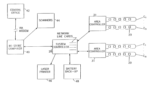
FIG. 2 illustrates the product information display system of FIG. 1 in block
form. The system includes a plurality of area controllers 31 coupling the
system
controller 28 to various sets of display tags 20. Each set of display tags 20
is
associated with one of the multiple wire loops C,-C~ connected to each area
controller
31. The area controllers 31 communicate with the tags 20 using a conventional
modulation protocol such as amplitude-shift-keying (ASK), which is a binary
form of
amplitude modulation. Other communication schemes, such as frequency shift
keying
(FSK) or phase modulation, can be used instead of ASK if desired.
Communication
between the area controllers 31 and the system controller 28 is effected using
a
conventional serial two-way communication protocol, preferably a network
interface
compatible with the RS422 or RS485 standard. Each of the area controllers 31
is
powered by a d-c. power supply within the system controller 28.
By controlling the display tags 20 through the area controllers 31, several
advantages are realized. For instance, the communication speed between the
system
controller 28 and the display tags 20 is increased (because it is not
necessary for the
system to talk to each tag), the processing power required in the system
controller 28
is decreased, and a level of modularity is provided for expanding use of the
display
tags 20. Further, use of the area controllers 31 significantly reduces the
cost of the
system by avoiding the need for an RS485 type interface at each tag.
-Both the tags and the area controllers store data and with their interactive
communications check each other as pan of the auditing and failure
identification
system. There is redundant power back-up with a battery in the system
controller
and in each area controller. The cost of individual tags is reduced because
certain of
the electronics in the area controller does not have to be duplicated in
thousands of
tags, and there is more flexibility for special display messages.
SUBSTITUTE SHEET (RULE 26)
WO 96/09619 ~ ~ ~ ~ ~ PCT/US95111913
The system of FIG. 2 also includes an in-store computer 40 which
communicates with a remotely located central office 42 using a modem. The in-
store
computer 40 provides a database of information, received from the central
office 42
(or from a scanner controller), for all the merchandise in the store. The
database is
S used to link each product with a physical-location address, an alpha-numeric
(or
UPC) description, a price, and a unit cost and general inventory information.
The
database may be accessed for the check-out scanners 44 as well as the system
controller 28. Changes in the database of the in-store computer 40 are
generally
initiated by updates received from the central office, but database changes
producing
10 display changes can also be made directly at the in-store computer 40.
After receiving the product data from the in-store computer 40. the system
controller 28 selects the desired display information and associated display
tag
address, and converts this display information into a data stream for
transmission to
the appropriate area controller 31. The area controller 31 then forwards this
information to the particular wire loop C,-Cn which includes the designated
tag 20.
Also associated with the system controller 28 is a printer 46 and a battery
back-up unit 48. The printer 46 may be used to make hard copies of the desired
displays, for example on regular or transparent paper, for insertion into a
shelf rail at
any locations not covered by the electronic tags 20. The printer can also be
used to
generate store or system reports. The battery back-up unit 48 is used to
maintain
system integrity during periods of power interruption.
As illustrated in FIG. 3, the system controller 28 may be implemented using a
personal computer 28 (such as a 486 or equivalent) containing a number of
network
boards configured for serial two-way communication with the area controllers
31. Or
communication can be accomplished with conventional RS422/RS485 interfaces or
equivalent. The system controller 28 also contains a conventional hard-drive
62 for
programs, protocols, addresses and storage, and power and data distribution
circuits
64a, 64b, etc. for all the area controllers 31 in the system. Each
distribution circuit
64 transmits and receives serial data over one set of lines 68 and sends d-c.
power
over another set of lines 70. A rechargeable 24-volt d-c. battery 72 is used
as the
power source, with an a-c.-powered battery charger 74 activated as necessary
to
maintain an adequate charge on the battery 72. The battery 72 is the primary
power
SUBSTITUTE SHEET (RULE 26)
WO 96/09619 PCT/US95I11913
11
source for the area controllers 31, emergency power for the system is also
provided
from this battery.
Referring now to FIG. 4, one of the area controllers 31 is shown in expanded
form. Each area controller 31 receives the data from the outputs of the
network
boards of the system controller 28 and translates the data into an
information/power
signal that is applied to one of the conductors C,-C~ for transmission to the
display
tags. Data transmission to the tags is typically at 1200 baud using ASK.
Each area controller 31 includes a network interface circuit 80 such as an
RS485 transceiver circuit, a microcomputer or microprocessor (MPU) 82, a
memory
84, and a plurality of transceiver circuits 86, one for each of the conductors
C,-C~.
Using the transceiver circuits. the microprocessor 82 receives the product
data from
the network interface 80 and determines on which conductor the display tag
address
resides. The microprocessor 82 then generates an information signal for
modulating
an a-c. power signal supplied to the selected conductor so that the
information signal
will be conveyed to the desired display tag 20. In a preferred embodiment, the
nominal frequency of the power signal carried by each of the conductors C,-C~
is
50 KHz.
Each transceiver circuit 86 in the area controller 31 includes a digital-to-
analog convener 88, a voltage-to-current driver circuit 90, and a phase-locked
loop
(PLL) circuit 92 or equivalent detector circuitry. The digital-to-analog
convener 88
converts the digital information signal from the microprocessor 82 into analog
form.
Alternatively, a straight analog communication scheme with an analog
oscillator can
be used. The resulting analog signal is connected to the input of the driver
circuit
90, which converts the analog voltage into a proportional current for driving
the
display tags 20 via one end of one of the conductors C,-C~. The other end is
terminated at ground for the area controller.
The area controller 31 also includes a transformer 87 whose primary is in
series with one of the conductors C,-C~. The transformer 87 produces a
secondary
voltage proportional to the primary current which is fed back to the voltage-
to-current
convener 90 and to the PLL input. The PLL circuit 92 senses the presence or
absence of the known sub-harmonic frequency signal from any of the tags. This
SUBSTITUTE SHEET (RULE 26)
WO 96/09619 ~ ~ ~ ~ ~ ~ PCflUS95/11913
12
signal is then decoded by the MPU 82. A superheterodyne receiver may be used
as
an alternative to the PLL.
A d-c. to d-c. convener and battery charger 94 is used to charge a back-up
battery 96, which provides at least one hour of operating power to the area
controller
31. The charger 94 receives its power from the 24-volt d-c. supply 72 in the
system
controller 28 (FIG. 3). Thus, in the event of a power failure in the system
controller
28, or during shelf relocation, the area controller 31 is able to provide
uninterrupted
power and control to the display tags 20 for at least one hour. This period of
time
should be sufficient to permit repair, and if more time is needed the battery
96 can be
backed up as needed, or the tags can be put in a sleep mode, as described in
more
detail below.
As illustrated in FIG. 4, the location of the input end of the conductor
alternates between the tag and bottom of vertically adjacent shelves. This
causes any
radiated signals from the loops on adjacent shelves to cancel each other. so
that the
overall system does not cause any radiation emission problems. The alternate
phasing of the loops also reduces cross-talk between adjacent conductors and
reduces
the susceptibility of the system to radiation from other sources.
FIG. 5 illustrates a preferred type of serial communication between one of the
area controllers 31 and the associated display tags 20. The serial data sent
from the
area controller to the display tags may include a tag address ("select one
tag") or a
selected group of tags, an "all tag" command to which all tags respond when
they
recognize a special address, a "load selected" command which includes a
particular
tag address, a "load subroutine" command which loads a set of data in the
unused
portion of a particular tag's memory, a "service inquiry" command to query
whether
any tags need to communicate with the area controller, a "reset" command for
resetting a particular tag, a "request checksum" command which is responded to
by a
tag sending a checksum corresponding to its ,down-loaded data (this is a price
verification routine), a "request data" command which invites a tag to send
selected
data to the area controller, or "sleep" or "wake-up" commands which
respectively
remove and apply on-board power to certain circuits for each tag.
The serial data sent from the display tag to the area controller includes
requests and responses. An "Ack" response means that the tag received the
SUBSTITUTE SHEET (RULE 26)
WO 96/09619 ~ ~ ~ ~ PGT/US95/11913
13
communication from the area controller, and a "Nak" response means that the
communication failed. A "Request" is an affirmative response to a service
invitation
to send data to the area controller, and "Data" is the data sent in response
to the area
controller requesting the data.
FIGS. 6 and 7 illustrate two different embodiments of the display tag 20.
Common reference numerals are used for common components in the two diagrams.
The differences between the embodiments of FIGS. 6 and 7 concern the type of
inductor 110 (or 110') utilized and the signal processing performed by a
rectification
circuit 114 (or 114'), a power supply circuit 116 (or 116'), and a signal
conditioning
circuit 118 (or 118').
Data sent to the display tag 20 via the conductor C is received by the display
tag 20 using inductive coupling. A pick-up coil or inductor 110 (or 110') is
located
close enough to the conductor C to cause the changing electromagnetic field
around
the conductor C to induce a corresponding current in the inductor 110. This
induced
current provides the display tag 20 with both the necessary operating power
and the
data for the display without requiring any physical contact between the
display tag 20
and the conductor C. The inductive coupling of both power and information
signals
to the tags eliminates the need for batteries in the tags and for physical
contacts
between the tags and the wire loop. This minimizes the cost of the tags, and
also
avoids problems caused by contact corrosion and electrostatic discharges.
The preferred embodiment of the pick-up coil 110 is a single coil with a full
wave bridge rectifier as shown in FIG. 6, but if desired two separate windings
may
be used, with one winding connected for data decoding (or demodulation) and
the
other winding connected for supplying power to the display tag. The pick-up
coil in
the preferred embodiment can be implemented by winding 43 turns of #32
enameled
wire in a channel molded into the outer periphery of the tag housing, as
described in
more detail below in connection with FIGS. 12 and 13.
A capacitor 112 is connected in parallel with the inductor 110 to form a
parallel tunedr circuit that is responsive to a particular range of
frequencies centered
about the carrier frequency transmitted by the area controller. This resonant
circuit
maximizes voltage gain and significantly improves coupling efficiency.
SUBSTITUTE SHEET (RULE 26)
WO 96/09619 PCf/US95/11913
14
In FIG. 6, the current induced in the coil 110 is sent through a full-wave
rectifier 114 to provide a positive input to a power supply circuit 116 and a
signal
conditioning circuit 118. The output of the voltage regulator 124, which is
connected
to a capacitor 126, provides operating power (V«) for the display tag 20. The
signal
conditioning circuit 118 is preferably a Schmidt buffer which improves the
rise and
fall times and the signal-to-noise ratio of the signal from the coil 110. The
circuit
118 can be implemented using a commercially available buffer having hysteresis
control.
In FIG. 7, the induced current is produced in a pick-up coil formed by a
center-tap inductor 110'. The ends of the inductor 110' are connected to a
pair of
rectifying diodes 114'. 114" to provide a full-wave rectified positive signal
for the
circuit 118'. The diode 114" can be removed (replaced by a wire) for an
operable
half-wave rectified sienal.
The power supply circuit 116' draws current from the center-tap of the
inductor 110' and includes a voltage regulator 124 and a capacitor 126 at its
output
for providing operating power (V~ for the display tag 20. The power supply
circuit
116' is connected to common (ground) for returning current through the diodes
114',
114" to the inductor 110' .
In both FIGS. 6 and 7, the output of the signal conditioning circuit 118 or
118' is pulse-extended using a monostable vibrator circuit 142. The output of
the
circuit 142 is monitored by a microcomputer (CPU) 146 for demodulating the
data.
A universal-asynchronous-receiver-transmitter (UART) 144 converts the
sequential
digital pulses from the circuit 142 into parallel format for use by the CPU
146, and
vice-versa. An oscillator 147 provides the operating clock signal for both the
DART
I44 and the CPU 146. A manually adjustable trimming resistor 149 replaces the
normally used crystal or ceramic resonator, but produces a much larger
variation in
oscillator frequency from tag to tag. This variation is compensated for by
synchronizing the oscillator frequency to the carrier frequency, thereby
permitting the
use of an R-C oscillator and eliminating the cost and size of a crystal. In
this
instance, the oscillator cycles are counted during each half cycle. or
multiple, of the
rectified main primary frequency (50 KHz wave rectified to 100 KHz wave). This
SUBSTITUTE SHEET (RULE 26)
WO 96/09619 PCT/US95/11913
count is then used to generate internal frequencies that may be needed for
communications.
Depending on the type of CPU 146 that is used, the buffer 118 (118'), the
monostable vibrator circuit 142 and the UART 144 may not be required, since
many
5 microcomputers have input ports which can accommodate and process analog
signals
directly. With such microcomputers, the UART-related functions are implemented
in
software.
The microcomputer (CPU) 146 uses conventionally configured operating
memory, including ROM 148 and RAM 150, and an LCD display memory 152, 154
10 for maintaining an assigned display set on an LCD display 156 and
communicating
with the area controller 31. The display 156 is preferably driven using a
conventional two-row display driver circuit 158 controlled by the CPU 146.
To permit input signals to be manually generated at the tag, a pair of
membrane switches 166 are accessible on the outside surface of the tag
housing.
15 Buffers 168, each having a conventional input pull-up resistor or current
source, are
connected to the switches 166, and the outputs of the buffers 168, are
supplied to the
CPU 146.
Use of low-power CMOS circuitry is preferred for the tags 20. This permits
the power draw from the conductor C to be maintained under 25 milliwatts per
tag.
In a preferred embodiment, a custom CMOS integrated circuit (IC) mounted on
the
printed circuit board contains all of the electronics except the display, the
tuned
circuit, the FET 159, the capacitor 126 and the switches 166, and requires
very little
power to operate.
The display tag 20 can transmit signals to the area controller 31 by an
impedance modulation scheme which changes the impedance of the tag circuit
that is
inductively coupled to the conductor C, thereby changing the impedance of the
loop
formed by the conductor C. This impedance change is detected by the phase-
locked
loop 92 in the area controller 31. To initiate such an impedance change in a
display
tag, the UART 144 turns on a JFET connected in parallel with the resonant
circuit
110, 112. The conduction of the JFET 159 shorts the capacitor 112, thereby
changing the impedance of the circuit coupled to the conductor C. Thus, by
modulating the impedance of the tag circuit by successively turning the JFET
159 on
SUBSTITUTE SHEET (RULE 26)
WO 96109619 -- PCT/US95/11913
16
and off, a signal may be induced in the conductor C at a frequency which is a
sub-
harmonic of the a-c. power signal which serves as the carrier signal.
To avoid naturally generated noise, the sub-harmonics are preferably
generated by rendering the JFET 159 conductive during odd-number half cycles
of
the a-c. power signal in the wire loop. For example, if the JFET 159 is turned
on
during only one half cycle out of three successive half cycles of the a-c.
power signal
in the wire loop, the frequency of the signal induced in the loop by the tag
is 2/3 the
frequency of the a-c. power signal. Naturally occurring sub-harmonics do not
occur
at odd fractions of the primary frequency, and thus will not interfere with
the signal
artificially generated by the impedance modulation.
With full wave rectification, the frequency of the induced signal is (2F~)/N,
where F~ is the carrier frequency and N is a positive odd integer. The half
cycle
count with full wave rectification is 2F~. When the FET is turned on every
third half
cycle, for example, N is 3 and the sub-hatTnonic is 2/3 F~.
In the preferred implementation of the impedance modulation scheme, a bit of
data is represented by a burst of one or more cycles of the artificially
generated sub-
harmonic signal. Successive bursts, of course, must be separated by periods of
no
impedance modulation to enable each separate burst to be detected as a
separate bit of
data.
To transmit both states of a binary bit of data, i.e.. a "0" or a "1", the a-
c.
power signal can be modulated at either of two different artificially
generated
frequencies. For example, a " 1 " can be represented by a signal having 2/3
the
frequency of the a-c. power signal, while a "0" is represented by a signal
having 2/5
the frequency of the a-c. power signal.
This impedance modulation technique is a way of transmitting data from the
tag to the area controller in a manner which is virtually powerless. The only
consumed power is that needed to turn the FET on and off.
Signals induced in the wire loop by impedance modulation in a tag are
detected in the phase-locked loop 92 in the transceiver 86 of the area
controller 31.
The area controller's micro-processor 82 then decodes this information and
determines which tag is the source of this signal. The area controller then
processes
SUBSTITUTE SHEET (RULE 26)
WO 96/09619 - PCTJUS95/11913
17
this data for functions controlled by the area controller such as check sums
for price
' verification or passes information onto the system controller 28.
Returning to FIGS. 6 and 7, the microcomputer 146 in the tag includes I/O
buffers 160 and capacitors 162 for storing an assigned the bits of charges
representing display tag address. The microcomputer 146 stores the down-loaded
address for the tag by writing the address to the I/O buffers 160. The ports
on the
other side of the buffers 160 are connected to the capacitors 162. In the
event of a
power failure, the address is preserved by the charge on the capacitors 162
for a
certain period of time. If desired, alternative means of temporary storage may
be
used.
As part of a multi-tiered power-backup system, the battery 96 in the area
controller 31 maintains all the tags serviced by that controller in normal
operation for
a selected time interval following a power failure. At the end of that time
interval,
which is determined by the MPU 82 in the area controller, the MPU 82 generates
a
signal which causes the CPU 146 in each tag to turn off the tag display. All
the
address and product information remains stored in the tag memory, including
the
capacitors 162. This second stage of the power-failure mode of operation is
continued for a specified period of time after which the data stored in each
tag's
RAM 148 and ROM 150 is erased, and only the tag addresses are preserved by the
battery backup in the area controller. When the battery is exhausted, the
capacitors
162 then preserve the addresses as long as the charge on the capacitors 162 is
sustained. In the event a tag is removed temporarily from a rail, the
capacitors 162
will maintain the address for a few minutes so that it is not necessary to
manually
reprogram the tag when it is reinstalled, as long as the address is
maintained. This
mufti-level approach provides extensive safeguards to a variety of power-
failure
conditions.
Address programming for each tag 20 is accomplished by entering the start-up
mode. The first address and associated product information data is generated
by the
system controller and fed to the area controllers for transmission to the
display tags.
This product information data appears on all the display tags running in the
start-up
mode. An installer then manually triggers a membrane switch 166 on the
particular
display tag which is to be identified by the first address. and which is to
display the
SUBSTITUTE SHEET (RULE 28)
WO 96/09619 - PCT/US95111913
18
product information data associated with that address and the shelf product
adjacent
to it. When the switch is triggered, the CPU 146 captures the address and
associated
product information data and exits the start-up mode, thereby initiating the
normal
run mode in the display tag. In the normal run mode, the display tag will
continuously display the product information data which is contained in the
memory
of the display tag until it receives an address which matches its stored
address, at
which time it will update the display in accordance with the information data
immediately following the received address.
Upon exiting the start-up mode, the display tag sends a confirmation signal
back to the system controller 28 via the conductor C and area controller 31 to
inform
the system controller that the first address has been captured by the
appropriate tag.
The system controller then sends the next address and associated product
information
data to the display tags. This new product information data is again displayed
on all
the tags that remain in the start-up mode. Visual inspection to make sure this
adjacent shelf product agrees with the tag displayed information and manual
triggering of successive display tags continues until all the display tags
have captured
addresses and display data. After any given display tag has captured an
address
during initialization, the system controller is able to update the information
in that tag
at any time.
During initial system installation only authorized personnel will have access
to
the display tag rails. Large retail stores typically have complete product
location data
in their databases, and thus the products in each area controller zone can be
sorted in
a sequence that enables the installer to walk down the aisle and activate the
tags
sequentially. This saves a significant amount of time.
As shown in the flow chart of FIG. 8a, for communication between an area
controller 31 and its tags, the data base for the tags associated with the
area
controller is first loaded via the system controller. Block 180 of FIG. 8a
depicts this
first step. After initiating the serial communication routines (block 182) and
sending
the product data for initializing the first tag (block 184), the MPU in ttve
area
controller determines if all tags on the system have been initialized (block
186). If
the data has been sent for all the tags, the step of down-loading is complete
and this
routine ends. as depicted at block 188. The initial pass through block 186.
however,
SUBSTITUTE SHEET (RULE 26)
WO 96/09619 _ ~ ~ ~ ~ ~ PCT/US95/11913
19
will lead to the step of block 190 in which the MPU broadcasts the information
for
the next tag associated with the area controller. At block 192. the MPU waits
for
one of the tags to respond. If the response is an "Ack" (block 194), flow
proceeds to
block 196 where the MPU increments the data buffer for initializing the
address for
the next tag and then proceeds back to block 186. If the response is not an
"Ack"
(block 194), flow proceeds to block 198 where the MPU determines whether a tag
has responded with a "Nak" . A "Nak" indicates an error which is handled in
block
199, and then flow returns to block 188. If it is neither an "Ack" nor a
"Nak", the
system tries to load the tag again until it times out. It then reports the
error and
proceeds to the next tag. This continues until all the tags are initialized
with the
appropriate address and product information.
FIG. 8b illustrates how each area controller operates once the step of down-
loading is complete. Blocks 200, 202 and 204 respectively depict starting the
normal
operation program, phase locking to the 50 KHz power signal and broadcasting
to the
tags for a service request.
At block 206, the area controller determines if one of the tags has responded
to the service request. If there is a response, the request for service is
handled as
. shown at block 208. If there is not a response, the area controller
determines that
there is no tag requesting service and flow proceeds to block 210 where a
communication check for each tag in the system is begun. At block 210, the
next tag
is selected. At blocks 212, 214 and 216, a cyclic redundancy code (CRC) is
requested from this next tag, returned by the tag and analyzed by the area
controller's
MPU to ensure that the tag data is correct and the tag is properly
communicating.
To ensure the integrity of the communication, the MPU preferably uses the
"Load
Subroutine" command to send data to the tag changing the loaded database. This
forces the tag to send back a new CRC, which the area controller checks and
verifies.
If proper communication is intact for the selected tag, flow proceeds to block
218 where the MPU determines whether all the tags have been serviced. If not
flow
returns to block 210 for servicing the next tag. If all the tags have been
serviced,
flow returns to the beginning of the program at block 200.
SUBSTITUTE SHEET (RULE 26)
WO 96/09619 ~ ~ ~ ~ ~ PCT/US95/11913
If the CRC is not intact for the selected tag, flow proceeds from block 216 to
blocks 220 and 222 where the area controller's MPU sends a down-load command
and down-loads the initialization data for the tag that is not properly
communicating.
From block 222, flow proceeds to block 224 where the MPU executes another CRC
5 poll, as described above, to ensure that the data was properly received by
the tag and
that the integrity is still intact. If the data was properly received, flow
proceeds to
block 218 to determine if all the tags have been serviced. If the data was not
properly received, flow proceeds to blocks 226 and 228 where the MPU continues
to
attempt to get the data to the tag for a period of time and then reports the
malfunction
10 to the system controller. From block 228, flow returns to block 204 where
another
broadcast service request is made and the process repeats.
Referring now to FIG. 9a, a flow chart shows how the display tae is
programmed to initialize the tag with an address and to bring the tag "on-
line" . This
programming mode starts at block 230 and proceeds to block 232 where the
15 microprocessor in the tag performs a power-on self-test (block 232)
involving
memory and register checks. At block 236, a test is performed to determine if
the
self test passed. If not, flow proceeds from block 236 to 234 where the tag
reports
the error via the visual display. If the self-test passes, flow proceeds from
block 236
to block 238, 240 and 242 where UART is initialized and the tag's clock is
adjusted
20 and phase-synchronized to the frequency (50 KHz) sensed on the power signal
carried
by the conductor. From block 242, flow proceeds to block 244 where the tag
temporarily assigns itself tag "00," so that it can receive the "Load All"
command
from the area controller for address initialization.
At block 246, the tag monitors the power signal on the conductor to determine
whether or not the tag has received a data packet. If a packet is received,
flow
proceeds from block 246 to block 248 where the tag stores the embedded
address.
Within the packet is the product information. From block 248, flow proceeds to
blocks 250 and 252 where the tag stores the information to be displayed and
displays
that information on the tag's visual display.
From block 252, flow proceeds to block 254. At block 254, the tag
determines if the initialization key (switch) has been manually pressed. If
not, flow
returns to block 246 to continually look for a packet transmitted to this tae.
From
SUBSTITUTE SHEET (RULE 26)
WO 96/09619 f ~ ~ ~ PC'I'/US95/11913
21
block 254, flow proceeds to block 256 in response to detecting that the
initialization
key switch has been manually pressed.
At block 256, the tag address received within the packet is adopted by the
tag.
From block 256, flow proceeds to block 258 where the tag goes on-line by
sending
an "Ack" communication to the area controller. At block 260, the tag is
depicted as
going on-line. This ends the program mode for initializing the tag.
After initialization, the tag is ready for normal operation, which is depicted
by
the flow chart in FLG. 9c. This flow chart begins at block 262 and block 268
where
the tag immediately begins monitoring the conductor to determine whether an
information pack has arrived from the area controller. If such a packet has
arrived,
flow proceeds from block 268 to block 270 where the tag compares the address
embedded in the information packet with the address of this tag to determine
if the
packet is for this tag. If it is not for this tag, the tag determines whether
the packet
represents a broadcast to all tags (such as "STORE IS CLOSING"), as depicted
at
block 272. If the information packet is for this tag, flow proceeds from block
270 to
blocks 274 and 278 where the tag identifies and executes the necessary action
associated with the received information packet.
From block 272, flow proceeds to blocks 274 and 278 if the packet is
associated with a broadcast for all tags (the "All tags" command).
From block 268, flow proceeds to block 280 in response to the tag
determining that a packet has not arrived over the conductor. At block 280,
the tag
performs a test to determine whether a manual button sequence has been
entered. If
such a sequence has not been entered, flow returns to block 268. If a manual
button
has been depressed, flow proceeds from block 280 to blocks 282 and 284 where
the
tag determines if the sequence is one of the valid sequences. If it is not a
valid
sequence, flow returns to block 268. If it is a valid sequence, flow proceeds
from
block 284 to block 286 where the command is executed. From block 286, flow
proceeds to block 288 where the buffer is cleared and flow returns to block
268.
The sequences are binary numbers entered by depressing membrane switches
representing "0" or "1". Valid sequences include binary sequences
corresponding to
requests for: resetting the tag; entering the cursor mode (FIG. 9c); verifying
the
SUBSTITUTE SHEET (RULE 26)
WO 96/09619 ~ ~ ~ PCT/US95111913
22
status of the tag and verification codes. Clearing the software buffer which
stores the
binary digits entered through the switches occurs after a time-out.
Turning now to FIG. 9d, a flow chart for implementing the cursor mode for
the display tag is shown. This routine is executed in response to a valid
manually-
entered sequence.
The cursor mode begins at blocks 290, 292 and 294, where the tag sets up the
display with a cursor position movable by one of the buttons, the scroll
button. At
blocks 296 and 298, the tag performs a test to determine whether a scroll
button has
been depressed. If so, flow proceeds to block 302 where the tag changes (or
scrolls
through) to the next cursor code position. From block 302, flow returns to
blocks
296 and 298 where the tag performs yet another test to determine if the scroll
button
has been depressed. This continues with the display code position being
changed
with each depression of the scroll button (switch). When the other switch (the
"select
button") is depressed, the current cursor position is equated with a package
(or
function), as indicated at block 306. The current position of the cursor is
returned to
the area controller thereby selecting the associated data block. The area
controller
may optionally await a verification to be entered into the buttons on this tag
before
acting on selected data.
In summary, one membrane switch is used to select a displayed code and
position the cursor to a selected display character position, and the other
switch is
used to terminate the cursor mode, selecting the last position of the cursor.
Such an
implementation is ideally used for reordering products and alerting the system
controller as to the status of the product for the associated tag.
From block 306 flow proceeds to block 308 where the tag sends the set of
selected codes to the area controller. At block 310, the tag resets the
display.
FIG. 10 illustrates a front view of the tag 20 shown in the previously-
discussed figures and FIG. 11 shows the details of the face of the LCD
display. The
printed circuit board or flex circuit carrying the electronic components for
the tag 20
is concealed within the tag housing 311. The front wall of the housing forms a
rectangular aperture for the LCD display, which includes four seven-segment
characters 313, a decimal point 314, an eight-segment units identifier 315,
and a
A
"for" annunciator 316 for displaying prices for quantity purchases: an 18-
character
SUBSTITUTE SHEET (RULE ~6)
WO 96/09619 PCT/US95/11913
:_
23
alpha-numeric display 317 (either 5 x 7 matrix or 14 segments) for product
descriptions; and a zone 318 with a combination of characters to display cost
per
unit. A display driver such as FD2258f/FC2258A/FC2258K manufactured by Fuji
Electric is used to translate the parallel data from the memory into the
conventional
drive signals for the LCD display. The display is shown to be of the LCD type,
but
LED's or other types of electronically controlled displays can be used. To
seal the
display window in the tag housing 311, a clear film may be bonded to the front
of
the tag housing to cover the display window.
FIGS. 12 and 13 illustrate a preferred arrangement for mounting the display
tags 20 on a conventional shelf 24 which includes a depending rail 22 formed
as an
integral pan of the shelf. An auxiliary rail 320 is snapped into the shelf
rail 22 and
extends continuously along the full length of the shelf for receiving both the
display
tags 20 and the conductor C.
The auxiliary rail 320 is designed so that the display tag 20 and the
conductor
C may be snapped into place anywhere along the length of the rail. The
insulated
conductor C is mounted in two channels 321 and 322 formed near the top and
bottom
of the rear wall of the rail 320. The tag is received in a channel formed in
the front
side of the rail 320. The tag is recessed inside, and held in place by, a pair
of
flanges 323 and 324 so that the tag does not protrude from the rail. The upper
flange
323 is flared outwardly at a slight angle so that it can be bent upwardly and
outwardly for installation and removal of tags from the front of the rail. A
pair of
rearwardly projection flanges 325 and 326 hold the rail 320 in place on the
shelf
rail 22.
As shown in the cross-section of the tag 20 in FIG. 12, the pick-up coil 110
is
wound around the periphery of the tag housing 311 in a channel 328 formed in
all
four edges of the housing. When the display tag is attached to the rail 320,
the coil
segments located in the top and bottom sections of the channel 328 are in
close
proximity to the two segments of the conductor C on the rear side of the rail
320.
Thus, the coil-is electromagnetically coupled to both segments of the
conductor C.
As shown in the perspective view of the tag of FIG. 13, a single conductor C
is snapped into the top channel 321 of the rail 320. spans the length of the
store
shelf. and then loops to the bottom channel 322 of the rail 320 and spans the
length
SUBSTfTUTE SHEET RULE 26)
CA 02200553 2001-07-18
24
of the shelf rail again. Alternate; phasing of vertically adjacent shelves, as
described
above in connection with FIG. 4, minimizes cross talk between adjacent
conductors
along the shelves and avoids any significant radiation of signals from the
entire
system or susceptibility from other sources.
FIG. 14 illustrates a displlay tag arrangement for products which are
displayed
on racks rather than shelves. Tl~iis type of display rack is commonly used for
products which are packaged in (blister packages. The rack includes multiple
rods
330, each of which supports multiple packages. A package can be removed from
the
rod by simply sliding the package off the forward end of the rod.
In the arrangement of FI(i. 14, a rail 320 is mounted directly above the rods
330, and contains a separate display tag 20 for each of the rods 330. The
conductor
C is fastened to the rear side of thf: rail 320 in the same manner described
above in
connection with FIGS. 12 and la.
FIG. 15 illustrates the use; of the electronic display tag system of invention
in
a warehouse environment. Many warehouses contain numerous bins containing many
different kinds of small articles vvhich are difficult to identify from the
markings on
the articles themselves. FIG. 15 contains a diagrammatic illustration of four
such
bins 340. To identify the articles in the respective bins, a rail 320 is
mounted
directly beneath each row of bins, and contains a separate display tag for
each bin.
Again, the conductor C is mounted on the rear side of each of the rails 320.
FIG. 16 depicts part of a retail store including a product information display
system arranged according to a preferred embodiment of the present invention.
Each
area controller 31 supplies both power and control signals to its display tags
20 via a
single main distribution loop and numerous branch distribution loops. As
described
above, the area controller 31 also monitors the display tags and receives
signals
generated by the tags, such as service requests and acknowledgement signals.
Each
area controller 31 is contained in an enclosed housing which is mounted on one
of the
gondolas 30 on which the shelves are mounted. Although the gondolas 30 in
FIGS.
16 and 17 are illustrated with only three shelves on each side, a gondola
typically has
about twelve shelves (six on each side), with an average of about six tags per
shelf,
or 72 tags per gondola. Thus, a single area controller can service 12 to 15
gondolas.
WO 96/09619 ~ PCTILTS95/i 1913
The main distribution loop connected to each area controller 31 is formed by a
series arrangement of two standard modules 422 and 423 (see FIG. 28). The
first
module 422 will be referred to herein as the "transfer module," and is simply
a pair
of parallel wires 424 and 425 encased in a dielectric strip 426 that can be
easily
5 attached to the top of a gondola 30. The dielectric surrounding each wire
preferably
has a thickness of about 0.015 to 0.020 inch to protect the system from
electrostatic
discharges. If desired, the flat side of the strip 426 may be coated with an
adhesive
426x, protected until installation by a releasable backing, to facilitate
application of
the strip to the gondola. The dielectric strip 426 containing the two wires
424, 425
10 can be manufactured in large quantities at a low cost by a conventional
extrusion
process. The distance between the wires 424, 425 is preferably minimized to
reduce
inductance. For example, when the wire is 18 AWG mufti-strand wire, the center-
to-
center spacing of the wires may be 0.125 inch. As illustrated in FIG. 19, the
mounting strip 426 is removed from a 2 to 3-inch length of both wires at both
ends,
15 and a quick connect 427 is crimped onto each exposed wire end.
The second module 423 used to form the main distribution loop will be
referred to herein as the "coupling module," and extends vertically along one
end of
each side of the gondola. Each coupling module 423 is a pair of parallel
conductors
430 and 431 joined at the lower end to form a U-shaped segment of the main
20 distribution loop. A single module 423 is used to distribute power and
control
signals to all the shelves on one side of a gondola. As in the case of the
transfer
module 422, the conductors 430, 431 in the coupling module 423 are encased in
a
dielectric strip 432 which covers the outside surface of each conductor 430,
431 with
a dielectric thickness of at least 0.015 to 0.020 inch to protect the system
from
25 electrostatic discharges.
To facilitate installation of the coupling module 423 in the 0.25-inch gap
that
normally exists behind the shelves on a gondola (see FIG. 20), the conductors
430,
431 are preferably in the form of thin flat strips of copper. e.g., 0.110 inch
by 0.018
inch. These strips are contained in channels of a dielectric strip 432 having
a total
thickness of 0.0446 inch, and are held in place by a thin insulating plastic
sheet 433
(FIG. 22) that is thermally bonded to the dielectric strip 432. A conductive
cross bar
434 connects the two conductors 430, 431 at the lower end of the strip 432. At
the
SUBSTITUTE SHEET (RULE 26)
WO 96/09619
PCT/US95/11913
26
upper end, the two conductors terminate in a configuration that mates with the
quick
connects 427 on the ends of the transfer module 422, so that the two modules
422
and 423 can be easily and quickly snapped together.
In order to facilitate coupling of the conductors 430 and 431 to the branch
distribution loops on the shelf rails, rectangular holes 435 are formed in the
central
web of the dielectric strip 432, at regular intervals along the length of the
strip. As
will be described in detail below, these holes 435 are used to receive a snap-
on
magnetic core module that couples the main and branch distribution loops. The
center-to-center spacing of the holes 435 along the length of the strip is
preferably the
same as that of the shelf mounting holes 436 in the shelf-support column 437
on the
gondola (FIG. 24), so that a hole 435 will always be located close to the rear
edge of
a shelf, regardless of where the shelf is mounted on the gondola. The coupling
modules 423 may be prefabricated in different lengths to match the dimensions
of
gondolas of varying heights.
To facilitate alignment of the transfer and coupling modules 422 and 423 at
the top of each gondola, and to enclose the connections between these two
modules,
the junction box 440 shown in FIGS. 24-28 is preferably used. This junction
box
442 also aligns the holes 435 in the coupling module 423 with the shelf
mounting
holes 436 in the gondola. This junction box 440 is formed in two parts 441 and
442,
joined by a series of snap locks formed by depending clips 443 on the upper
part 441
and mating holes 444 in the lower part 442. The upper ends of the coupling
modules
423 are aligned by a pair of plugs 445 which fit through a corresponding pair
of
holes 446 in a pair of opposed vertical walls 447 and 448 of the junction box.
The
prongs on the inner ends of the plugs 445 fit into corresponding holes 449
(FIG. 24)
near the upper ends of the coupling modules 423, thereby fixing the positions
of the
upper ends of the coupling modules both horizontally and vertically.
The transfer module 422 on the top of the gondola is registered in a pair of
notches 450 formed in the lower ends of a pair of guide legs 451 depending
from
opposite sides of the upper part 441 of the junction box. This registration
ensures
that the quick connects 427 on the end of the transfer module 422 will be
conveniently located with respect to the upper ends of the conductors 430 and
431 in
the coupling module 423.
SUBSTITUTE SHEET (RULE 26)
WO 96/09619 _ PCT/US95/11913
°'
27
To position the junction box 440 itself, the lower part 442 has a depending
alignment leg 452 which fits into the interior of the shelf-support column 437
of the
gondola. The open top of this steel column 437 is normally closed with a
plastic cap,
which can be simply removed and replaced with the lower part 442 of the
junction
box. Thus the junction box 440 will always be precisely positioned with
respect to
the ends of the gondola shelves, whose positions are fixed by the steel column
437.
Each shelf 24 has its own branch distribution loop, mounted on the rear side
of an extruded plastic rail 460 that snaps onto the front of a standard shelf.
FIGS. 29
and 30 illustrate a preferred arrangement for mounting the display tags 410 on
a
conventional shelf 412 which includes a depending rail 461 (FIG. 34) formed as
an
integral pan of the shelf. The auxiliary rail 460 is snapped into the shelf
rail 461 and
extends continuously along the full length of a shelf 412 for receiving both
the
display tags 20 and the branch loop.
The auxiliary rail 460 is designed so that the display tags 20 and a conductor
462 that forms the branch loop may be snapped into place on the rail. The
insulated
conductor 462 is mounted in two channels 463 and 464 formed near the top and
bottom of the rear wall of the rail 460. The tags 20 are received in a channel
465
formed in the front side of the rail 460. The tags are recessed inside. and
held in
place by, a pair of flanges 466 and 467 so that the tags do not protrude from
the rail.
A curved rib 465a extends across a major portion of the space behind the upper
flange 466 so as to form a spring element that can be deflected by pressing a
tag
upwardly behind the flange 466; the rib 465a then exerts a biasing pressure on
the
inserted tag to hold it in place on the rail 460. A hollow core 468 on the
rear side of
the rail 460 snaps into the open recess formed on the front of a standard
shelf rail
461 to hold the rail 460 in place on the shelf rail 461.
When a display tag 20 is attached to the rail 460, a pick-up coil on the tag
is
in close proximity to the two parallel runs of the conductor 462 on the rear
side of
the rail 460. Thus, the pick-up coil is electromagnetically coupled to both
segments
of the conductor 462. The conductor 462 is snapped into the top channel 463 of
the
rail 460, spans the length of the store shelf 24, and then loops to the bottom
channel
464 of the rail 460 and spans the length of the shelf rail again. Alternate
phasing of
vertically adjacent shelves minimizes cross talk between adjacent conductors
along the
SUBSTITUTE SHEET (RULE 28)
WO 96/09619 PCT/US95/11913
28
shelves and avoids any significant radiation of signals from the entire system
or
susceptibility from other sources.
At the rail end adjacent the vertical coupling module 423, the conductor 462
is
extended to form a U-shaped segment 470 that can be magnetically coupled to
the
module 423. As can be seen in FIGS. 30-33, the portion of the U-shaped
extension
470 adjacent the end of the rail 460 is simply a side-by-side extension of the
two runs
of wire 462 mounted on the rail. This portion of the extension 470 is long
enough to
traverse the underside of the shelf, from the front edge to the rear edge, and
may be
provided with an adhesive coating on one side to facilitate attachment thereof
to the
underside of a shelf. At the lower end of the rear edge of the shelf, the two
ends of
the wire 462 are joined to two legs of a U-shaped flat conductor 471 enclosed
in a
thin, flat dielectric case 472. This flat conductor 471 is similar to the flat
copper
conductors 430, 431 in the coupling module 423, and the closed end portion 473
of
the encased U-shaped conductor 471 has exactly the same width and thickness as
the
coupling module 423. It also has a rectangular hole 474, between the legs of
the U.
of exactly the same dimensions as the holes 435 in the coupling module 423.
Accordion folds 475 are preferably formed near the open end of the U to permit
the
length of the U to be varied slightly to accommodate small variations in the
distance
between the rear edge of the shelf and the nearest hole 435 in the coupling
module
423.
To form a magnetic coupling between the branch and main distribution loops,
the flat U-shaped portion 471 of the branch loop extension 470 is placed flat
against
the coupling module 423 with the rectangular holes 474, 435 in the two flat
elements
in exact register with each other. A two-piece magnetic core 480 is then
clamped
against opposite sides of the two flat elements, and fastened together by a
hinged
dielectric casing 481 attached to the two parts of the core. One part of the
magnetic
core 480 is an E-shaped piece 482 in which the middle arm 483 of the E is
dimensioned to fit into and extend through the registered rectangular holes in
the two
flat elements 473 and 423. The other two arms 484 and 485 of the E extend
along
the outside edges of the two flat elements.
The second pan of the magnetic core 480 is a straight piece 486 which closes
the open side of the E when the two pieces 482 and 486 are brought together.
The
SlIBSTlTUTE SKEET (RULE 2fi)
WO 96/09619 PCT/US95/11913
29
resulting core completely surrounds the two conductors in both flat elements
473 and
423, as can be seen in FIG. 38, and also fills the common central opening
formed by
the registered holes 474, 435 between the two pairs of conductors. Thus,
current
flow in either loop 470 or 423 will induce a corresponding current flow in the
other
loop through the magnetic coupling. The energy transfer through the magnetic
coupling is highly efficient, e.g., as high as 95%.
To hold the two pieces of the magnetic core together, with the two flat
elements 473 and 423 sandwiched between the core pieces 482 and 486, the
hinged
dielectric case 481 for the core pieces includes a latch that snaps closed as
the two
core pieces are brought into engagement with each other. Specifically, a
channel 487
with an inturned lip 488 formed on one free end of the housing flexes
outwardly as it
is forced past an angled lip 489 on the other free end of the housing. When
the
edges of the two lips 488 and 489 clear each other, the outer lip 488 snaps
into the
groove formed by the inner angled lip 489. This snap-action latch enables an
installer to quickly and easily assemble the magnetic couplings that join the
numerous
branch loops to the various coupling modules 423 in the main loop. If the
shelves
are re-arranged at a later time, the core module can be easily unlatched, re-
located,
and re-latched. The two core pieces 482 and 486 are preferably pre-attached to
their
hinged case 481 by adhesive bonding so that the two core pieces and their case
can
be handled as a single pan during assembly and dis-assembly of the magnetic
coupling.
The modular construction of this invention permits large display tag systems
to be assembled from only a few different types of prefabricated modules. The
principal modules are the transfer module and the coupling module that make up
the
main distribution loop, the rail module that includes a branch distribution
loop, and
the magnetic core module. The junction box is not pan of the electrical system
but is
another repetitive module that facilitates assembly of the electrical modules.
Mass
production of this relatively small number of modules reduces the overall cost
of the
display tag system, and significantly shortens the time required for
installation.
Moreover, the resulting system is highly reliable and relatively maintenance-
free
because of the small number of electrical contacts subject to corrosion. The
system
is also largely immune from damage from electrostatic discharges because all
SUBSTITUTE SHEET (RULE 26)
WO 96/09619 ~ ~ ~ ~ PCT/US95i11913
vulnerable portions of the system are enclosed in protective casings. Finally,
this
system provides virtually unlimited flexibility for the owner to re-locate any
desired
section of the display or storage facility with only minimal additional work
to
disconnect and re-connect the display system.
St1$STiTUTE SHEET (RULE 26)