Note: Descriptions are shown in the official language in which they were submitted.
2200906
96 P 7419
SERPENTINE MOLDED BUS BAR BARRIER
FIELD OF THE INVENTION
The present invention relates generally to electric
load centers, and more particularly to an improved load
center and load center components.
BACKGROUND OF THE INVENTION
Electric load centers suffer from a number of
limitations. Assembling the various components of the load
center such as the trim panel to the metal enclosure of the
load center oftentimes requires an electrician to align the
holes in these components, insert screws through the
aligned holes, and screw each screw into the holes. Such
activities are time consuming and are oftentimes not
successful on the first attempt and have to be repeated
several times. In accordance with an aspect of the present
invention, a push-in screw holder fixture for the metal
enclosure is provided which enables an electrician to
easily secure the trim to the metal enclosure.
There is sometimes created an overpressure condition
within a load center which can cause the door of prior art
load centers to be forced open. In accordance with an
aspect of the present invention, a new and improved latch
is provided which, during an overpressure condition within
the load center, causes the latch to engage the latch
receptacle on the trim panel even more securely so that the
door does not open.
Because load centers are constructed in varying sizes,
for each size of load center constructed by a manufacturer,
a separate inventory of basepans had to be manufactured and
maintained. A need has therefore developed for basepans
which are adaptable to various sized load centers and which
are relatively inexpensive to manufacture. This need was
partially met by the production and use of extruded
CA 02200906 2005-01-05
20365-3661
2
basepan pieces were' constructed for interconnection to
accomplish circuit breaker load centers of adjustable
length. Because angular mounting of components is not well
suited to robotic assembly, some prior art basepans and
modular extensions have had to be adapted to be vertically
down loaded to mating portions of the basepan, or have been
adapted to be horizontally or laterally connected td mating
portions of the basepan. Such attachment methods and
modular construction may not be desireable and can result
in imprecise spacing between the connected modular pieces,
which may affect the subsequent assembly and installation
of components to the basepan and the basepan to the
enclosure. In accordance with an aspect of the present
invention, new and improved basepan and modular extension
basepan components are provided which can be robotically.
assembled, but needhot be robotically assembled in solely
a vertical drop-down mode or a lateral mode, and which
reduce the possibility of misalignment and improper spacing
between connected modular pieces.
Securing the basepan to the enclosure is oftentimes
time consuming.and cumbersome. In accordance with an
aspect of the present invention, an improved basepan is
provided having mounting features which facilitate the
assembly of the basepan to the enclosure, thus saving time
and labor.
It is well known in the art to provide an electrically
insulative barrier between the bus bars of load centers.
In accordance with an aspect of the present invention, an
improved basepan having integrally formed electrical
insulative barrier is provided between the bus bars which
increases the protection from the occurrence of arc
tracking as well as decreasing the possibility of
sustaining the arc, once it has occurred.
Bus bars have been secured to the basepan by common
fastening devices such as screws, bolts and ~snap-in
fasteners (U.S. Patent No. 4,536,823, Aug. 20, 1985) which can
be cumbersome, time consuming to apply, uneconomical, require
. = CA 02200906 2005-07-13
3-
extra parts, and most importantly can impart stresses to
the- component being secured and adversely effect tho
structural integrity of the component. Applying ultrasonic
energy to posts which are integral parts of a plastic
basepan as a means of deforming the post to secure bus bars
to the plastic basepan is well known (U.S. Patent
4,118,754, Oct. 3, 1978). Heat staking as a m ans of securinQ
ccuporientts to a plastic basepan can be advantageous in overoag the
above-stated disadvantages of common fastenirng devices, but
imparts stresses which concentrate at the face of the
basepan where the base of the po$t intersects the basepan
to form corners. Such stress can significantly impair the
integrity of the connection by causing a fracture of the
post, loss ~of the integrity of the connection, . and a
decrease in thi service life of the basepan and the load.
center. In accordance with an'aspect of the present
invention, an improved basepan is provided having
integrally formed, posts for securing thereto components
such as bus bars and the like by heat staking which reduces
the stresses imparted to the posts and basepans from heat
staking.
As is well known, it has been difficult.for installers
to secure return wires to the neutral bars of the prior art
load centers because it is generally difficult to see the
holes in the neutral bar into which the wires are to be
placed. In order to improve the visibility of the holes in
the neutral bar into which the return wirss of the power
circuits are to be inserted and secured, and thereby
facilitate the connection'of the neutral -return wires* to
the neutral bars by the electrical installer, in accordance
with anaspect of the present invention an improved neutral
bar is provided which allows.for viewing of the electrical
connector apertures positioned in the side walls when
viewed either directly overhead or froa the side.
Also, prior art attachment methods between the.neutral
bar=and the basepan are unsatisfactory. In accordance with
2200906
96 P 7419 4
an aspect of the present invention, the neutral bar is
adapted to permit simplified assembly and mounting to the
basepan. This is accomplished by providing a configuration
of the neutral bar and an improved basepan to which the
neutral bar is attached which does not require the use of
screws or other separate fastening devices thereby reducing
the number of components in the load center and
facilitating the mounting of the neutral bar to the
basepan.
Furthermore, in order to further facilitate the
installation of the return wires to the neutral bars of the
load center, in accordance with an aspect of the present
invention, an improved basepan is provided having an
integrally formed neutral bar wire guide which assists the
electrician or installer in guiding the wires of power
distribution circuits into the electrical connector
apertures in the neutral bars.
In accordance with another aspect of the present
invention, an improved neutral tie bar is provided which
connects the neutral bars together. Some load centers of
the prior art are not grounded because the installer or
user neglects to do so. There is nonetheless a need to
assure that there is no potential difference between the
neutral and the ground. In accordance with this aspect of
the present invention, the neutral tie bar is adapted to be
capable of being electrically connected to the outer metal
enclosure of the load center thereby eliminating any
potential difference between the neutral and ground of the
load center. Since each power company providing service
maintains the potential of the neutral at or close to zero
volts, the function of connecting the neutral of the load
center to the ground is accomplished by electrically
connecting the neutral tie bar to the metal outer
enclosure.
In accordance with an aspect of the present invention,
a new and improved main lug insulator or barrier is
provided between the incoming service and the other
220090a~
96 P 7419 5
components in the load center functions to: insulate each
of the main lugs from the neutral bus bar, neutral tie bar,
and neutral lug(s); reduce incidental shorting or
inadvertent energization of current carrying conductors
both during installation and subsequent operation; and
maintain required over-surface and through-air spacing for
cooling and expansion of the main lugs.
SUMMARY OF THE INVENTION
In accordance with the invention, the enclosure of the
load center is adapted to receive and is fitted with a
push-in screw holder fixture comprising an open ended u-
shaped structure formed by folding a piece of sheet metal
having; (a) an upper surface having two tabs formed
therein, facing one another and directed inward and
downward, each of said tabs having a free edge forming an
opening therebetween for receiving the threads of a screw
and which deflect upon axial pressure to form a one way
opening, the upper surface further having two outwardly
extending flanges; and (b) two sidewalls extending downward
and substantially orthogonal from the upper surface, each
of said sidewalls having a tab formed therein and directed
outwardly and upwardly for clasping an edge of the hole
between the upwardly and outwardly directed tab and the
outwardly extending flange.
The door latch of the load center comprises a one-
piece molded member disposed in an opening in the door, the
one-piece member having a planar top with an indent for
opening the latch, a body portion extending from an
underside of the planar top which is slideably received in
an opening in the door, the body portion having a flexible
tongue extending in an upwardly direction at an angle away
from the body and towards the free edge of the door. The
one-piece molded member further includes a hook disposed
from the underside of the top, the hook having a free end
extending toward the tongue of the body for engaging an
2200906
96 P 7419 6
underside edge of a portion of a trim panel of the load
center and which is adapted to form an aperture adjacent
the opening in the door. The tongue urges the door latch
towards the first edge of the door, keeping the hook
biasedly engaged with the underside edge of the portion of
the trim panel adapted to form the aperture.
The basepan of the load center is an integrally formed
snap-on basepan comprising a one piece molded member having
a planar surface for mounting the bus bars, at least one
circuit breaker support rail extending upward from said
planar surface for supporting the circuit breakers in the
load center, the circuit breaker support rail having at one
end an upper end wall and at a second end a lower end wall,
said lower end wall being adapted to have a slot with an
upper edge. The snap-on basepan having at least one
modular extension mounting foot extending from the lower
end wall for receiving a modular extension basepan to
extend the length of the snap-on basepan. The modular
extension mounting foot comprising an upper wall and two
sidewalls and a front wall and a rear wall being arranged
to form a hollow rectangular box, said rear wall being
formed by the end wall of said circuit breaker support
rail, the upper wall and one of the two sidewalls of the
modular extension mounting foot having a trapezoidal shaped
slot extending therethrough for engagement by a
correspondingly shaped ramp of the modular extension
basepan to align the modular extension basepan to the snap-
on basepan. The upper wall of the modular extension
mounting foot further including an aperture for passing
therethrough a flexible snap hook extending from the
modular extension basepan to engage the upper edge of the
slot formed in the lower end wall of the circuit breaker
support rail and to thereby secure the modular extension
basepan to the snap-on basepan.
The basepan of the load center comprises a planar
surface for the mounting of bus bars, the planar surface
having a tab extending from an edge of the planar surface,
CA 02200906 2006-11-08
20365-3661
7
the tab having a tapered lower edge and a prong extending
from a side edge. The basepan further having ears extending
from the planar surface and disposed toward opposite sides
of the basepan, each of the ears having an aperture for the
passage of a screw. The enclosure of the load center has a
lance formed from a backwall, the lance having a free end
disposed away from the backwall and into the interior of the
enclosure for capturing the tab of the basepan, the
enclosure further having a hole in the backwall for
receiving a screw. As the basepan is being mounted to the
enclosure, the tapered lower edge of the tab is captured
between the lance formed in the backwall of the enclosure
and the interior face of the backwall and the prong is
engaged by an upper edge of the tab to stop the vertical
movement of the basepan while the ears of the basepan are
placed into abutting relation with the interior surface of
the backwall for mounting by a screw through the aperture
and into the correspondingly positioned hole in the
enclosure.
In accordance with one aspect of the invention,
there is provided a basepan for an electric load center
having a first and a second bus bar, the basepan comprising
a planar surface for receiving the first and the second bus
bars, the planar surface having two spaced apart
substantially parallel walled members, said walled members
integrally formed with and extending substantially
orthogonally upwards from the planar surface to form a
continuous serpentined double-walled barrier between the
first bus bar and the second bus bar.
The basepan of the load center comprises a surface
to which a selected component of the load center is to be
mounted, the surface having at least one integrally formed
post for peening over by heat staking to secure the selected
CA 02200906 2006-11-08
20365-3661
7a
component to the basepan, wherein the integrally formed post
has a torroidal shaped undercut extending around a periphery
of the post at the intersection with the surface of the
basepan.
In accordance with another aspect of the
invention, there is provided a load center comprising an
enclosure, a pair of bus bars located within the enclosure
for interconnecting a line supply with a plurality of
circuit breakers located within the enclosure, a basepan
mounted within the enclosure, the bus bars having integrally
formed stabs which extend in parallel planes perpendicular
to a longitudinal axis of each bus bar and aligned in a row
in an interleaved face to face relation, free ends of each
of the stabs being mechanically and electrically connected
within recesses in a plurality of circuit breakers, and an
electrically insulated barrier disposed between the bus
bars, the electrically insulated barrier having a double
wall serpentined structure composed of an electrical
insulative material having at least two serpentined walls
integrally formed with and extending substantially
orthogonally upwards from a planer surface of the basepan,
the serpentined structure positioned on the basepan to
provide a continuous double walled physical barrier between
the pair of bus bars.
A neutral bar is provided having an elongated
central body portion with a trapezoidal shaped cross-
sectional area with
2200906
96 P 7419 8
outwardly sloping downwardly extending side walls, the side
walls having a plurality of apertures for insertion of
electrical wires, a top portion extending from the central
body portion and having a plurality of tapped holes at
least one of which is in communication with a corresponding
one of the plurality of apertures in the side walls, and a
base portion extending from the central body portion for
mounting to the basepan.
The basepan of the load center comprises a surface
member for mounting components of the load center and a
channel for mounting a neutral bar having a plurality of
electrical connector apertures for receiving neutral return
wires, the surface member further including an integrally
formed neural bar wire guide comprising a wall upwardly
extending from the surface member, the wall having
semicircular slots extending therethrough at an upper
surface, each one of the semicircular slots for receiving
a return wire and guiding the return wire therethrough and
into a preselected one of the plurality of electrical
connector apertures in the neutral bar.
An improved neutral tie bar for connecting together
the neutral bars of a load center having a metal outer
enclosure, the neutral tie bar comprising: (a) a center
portion having two vertically offset laterally extending
ends, each of said ends having an aperture for receiving a
screw to secure each of said ends to a neutral bar; (b) a
pair of first elevated members, each one of said pair of
first elevated members being disposed between the center
portion and one of said ends and adapted to form a branch
neutral cable lug having a horizontally disposed bore for
receiving a branch neutral cable, the branch neutral cable
lug further having a vertically extending tapped bore in
communication with the horizontally disposed bore, said
vertically extending tapped bore for receiving a threaded
clamping screw to secure the branch neutral cable; (c) a
second elevated member disposed between one of said pair of
first elevational portions and one of the vertically offset
2200906
96 P 7419 9
laterally extending ends, said second elevated member being
adapted to form a neutral cable lug having a horizontally
disposed bore for receiving a neutral cable, the neutral
cable lug further having a vertically extending tapped bore
in communication with the horizontally disposed bore, said
vertically extending tapped bore for receiving a threaded
clamping screw to secure the neutral cable. The neutral
tie bar can be electrically connected to the metal outer
enclosure of the load center.
A main lug insulator for an electric load center,
comprising: a first and a second trough-shaped
longitudinally extending compartment, each of said first
and second compartments comprising a horizontally disposed
platform from which extends two upstanding walls having
first edges which form a first open end and having second
edges which form an oppositely facing second open end; a
first support leg extending downward from the first edges
forming said first open ends; a second support leg
extending downward from the second edges forming said
second open ends; said first support leg being spaced apart
and substantially parallel to said second support leg to
form an open laterally extending space therebetween and
below the platforms for positioning over a neutral tie bar
of the load center.
BRIEF DESCRIPTION OF THE DRAWINGS
Figure 1 is a perspective view of the load center
incorporating the principles of the present invention;
Figure 2 is a plan view of the outer enclosure of the
load center shown in Figure 1;
Figure 3 is a plan view of the trim panel which
encloses the outer enclosure shown in Figure 2;
Figures 4A, 4B, and 4C are top and side views of a
push-in screw holder;
Figure 5 is a front view of the door mounted to the
trim panel shown in Figure 3;
2200906
96 P 7419 10
Figures 6A and 6B are perspective views of the door
latch from above and below respectively;
Figure 6C is a side view of the door latch;
Figure 6D is a sectional view of the door latch shown
in Figure 6A taken along line 6d-6d;
Figure 6E is a sectional view of the door latch
mounted to the door and secured closed to the door trim;
Figure 7 is an isolated perspective view of the
basepan shown in Figure 1;
Figure 8 is a top plan view of the basepan shown in
Figure 7;
Figure 9 is an enlarged plan view of a modular
extension mounting foot of the basepan shown in Figures 7
and 8;
Figure 10 is a sectional view of the modular extension
mounting foot taken along line 10-10 in Figure 9;
Figure 11 is a sectional view of the modular extension
mounting foot taken along line 11-11 in Figure 9;
Figure 12 is a top plan view of a modular extension
basepan for connection to the basepan shown in Figures 7
and 8;
Figure 13 is a sectional view of the modular extension
basepan taken along line 13-13 in Figure 12;
Figure 14 is a sectional view of a portion of the
modular extension basepan taken along line 14-14 in Figure
13;
Figure 15 is an enlarged plan view of the mounting
foot of the modular extension basepan shown in Figure 12;
Figure 16 is a sectional view of a portion of the
mounting foot taken along line 16-16 in Figure 15;
Figure 17 is a sectional view of a portion of the
mounting foot taken along line 17-17 in Figure 15;
Figure 18 is a sectional view of the basepan taken
along line 18-18 in Figure 8;
Figure 19 is a sectional view of the enclosure taken
along line 19-19 in Figure 2;
2200906
96 P 7419 11
Figure 20 is a perspective view of the interior
components of the load center in Figure 1 showing the
basepan with circuit breakers removed;
Figure 21 is an enlarged plan view looking down on a
portion of the basepan shown in Figure 20 taken along line
21-21;
Figure 22 is a sectional view taken along line 22-22
in Figure 21 showing a double walled serpentine barrier
between the bus bars;
Figure 23 is a sectional view taken along line 23-23
of the integrally formed hollow post shown in Figure.8;
Figure 24 is a sectional view taken along line 24-24
of the integrally formed solid post shown in Figure 8;
Figure 25 is a cross-sectional view of a neutral bar
taken along line 25-25 in Figure 20;
Figure 26 is a top view of the neutral bar shown in
Figure 20;
Figure 27 is a cross-sectional view of upwardly
extending flexible snap hook taken along line 27-27 in
Figure 8;
Figure 28 is a side elevational view of neutral bar
wire guide taken along line 28-28 in Figure 8;
Figure 29 is a sectional view of the neutral tie bar
taken along line 29-29) in Figure 30;
Figure 30 is a top view of the neutral tie bar shown
in Figure 20;
Figure 31A is a perspective view of the main lug
insulator shown in Figures 1 and 20;
Figure 31B is a top view of the main lug insulator;
Figure 31C is a sectional view of the main lug
insulator taken along line 31C-31C in Figure 31B;
Figure 31D is a rear elevational view of the main lug
insulator shown in Figure 31A; and
Figure 31E is a side view of the main lug insulator
shown in Figure 31A.
~2 10
96 P 7419 12
DETAILED DESCRIPTION OF THE INVENTION
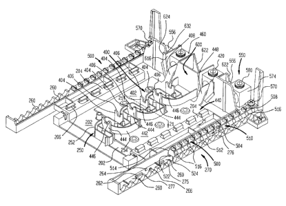
Referring to the drawings, a load center for use in
residential or light commercial applications is indicated
in Figure 1 by the reference numeral 1. The load center 1
includes an enclosure 10, trim panel 50, supporting basepan
200 mounted therein, door 80, door latch 120, bus bars 400
and 440, neutral bars 500, neutral tie bar 550, main lugs
420 and 460, neutral lug 574, main lug insulator 600, and
distribution circuit breakers. Although not shown, load
center 1 may alternatively include a main circuit breaker
instead of direct main lug connectors 420 and 460 which
connect the incoming service or main lines to the
components of the load center and which functions to
provide a means to interrupt power to the load center.
Referring to Figure 2, enclosure 10 comprises a
backwall 12 and four integral sidewalls 14,16,18 and 20
which terminate in inwardly turned peripheral lips 22,24,26
and 28 respectively, surrounding an open front of enclosure
10. Enclosure 10 is typically manufactured from sheet
metal in a series of operations including cutting,
blanking, forming and welding. Enclosure 10 is typically
installed between the wall studs of a building partition,
so that the open side of the enclosure is flush with the
partition outer surface. Enclosure 10 is covered by a trim
panel 50 shown in Figure 3 for flush fit with the enclosure
and the partition. Trim panel 50 is attached to enclosure
10 with fasteners, such as screws, which pass through holes
52 formed in the trim panel and into peripheral lips 22 and
26 of sidewalls 14 and 18 shown in Figure 2. The trim
panel 50 has a hinged access door secured by a latch which
allows access to the interior of the load center so as to
permit user manipulation of circuit breaker actuation
handles located in the load center.
When installing a trim panel to an enclosure of the
prior art, the electrician generally has to align the holes
formed in the trim panel with the corresponding holes
located in the enclosure, insert screws through the aligned
2200906
96 P 7419 13
holes, and screw each screw into the enclosure. This task
is time consuming and is oftentimes not successful on the
first attempt and has to be repeated several times.
In accordance with an aspect of the present invention,
enclosure 10 is adapted to receive and is fitted with a
push-in screw holder fixture which enables an electrician
to secure trim panel 50 to enclosure 10 by merely pushing
a screw through the aperture 52 in the trim panel and into
the push-in screw holder mounted in a lip of the enclosure.
Referring to Figures 4A,4B and 4C, push-in screw
holder 40 is shown and comprises an open ended, "U"-shaped
structure, formed of a single piece of sheet metal where
the U-shape is formed by folding the sheet metal to form an
upper surface 41 and two sidewalls 43 extending from the
upper surface. The upper surface 41 has two outwardly
directed flanges 42. A one way opening 49 is formed in
upper surface 41 by two tabs 44 directed inward and
downward as more fully discussed below, to receive a
threaded fastener. At each of two opposite sidewalls 43 is
a cut out tab 46 directed outwardly and upwardly. A push-
in screw holder fixture 40 is inserted within
correspondingly shaped holes 30 in lips 22 and 26 (shown in
Figure 2). Outward extending flanges 42 aid in fixing the
push-in screw holder 40 in place in hole 30 in the
enclosure, clasping the edges of hole 30 between the
outwardly extending flanges 42 and the upwardly and
inwardly directed tabs 46.
At the time of installation of the trim panel 50 to
enclosure 10, trim panel apertures 52 are aligned with
push-in screw holders 40 in lips 22 and 26 of enclosure 10,
and a screw is pushed through each of the trim panel
fastener apertures 52 and into the one-way opening 49 in
each of the push-in screw holders 40.
Inward and downward cut out tabs 44 of push-in screw
holder 40 act as spring-loaded fingers or leaf springs
which deflect upon the axial pressure being exerted by a
screw being pushed into the push-in screw holder. The free
22009VP
96 P 7419 14
edges 47 of tabs 44 forming opening 49 engage the threads
of the screw thereby precluding linear withdrawal (i.e.,
pulling the screw out in the opposite direction to the
direction of insertion) without rotation of the screw in a
counterclockwise direction.
In the event of an overpressure condition within a
load center which can be caused for example by a short
circuit fault, the door of some prior art designed load
centers can be caused to burst open. More specifically,
the door can be bowed outward which can cause the door and
therefore the latch mounted on the door of the prior art
designs to move away from engagement with the latching
receptacle generally located on the trim until the door
latch becomes disengaged from the latching receptacle
allowing the door to be pushed open by the overpressure
condition. In accordance with an aspect of the present
invention, a new and improved latch is provided which,
during an overpressure condition within the load center,
causes the latch to engage the latching receptacle on the
trim even more securely so that the door does not disengage
and open.
Referring to Figure 5, door 80 is shown mounted to
trim panel 50 by hinges 82. Mounted on face 84 of door 80
is door latch 120 shown in Figure 6A. Door latch 120 is a
one-piece molded member comprising a top 122 having an
indent 124 for engagement of the operator's finger for
opening and closing latch 120. Opening latch 120 is
accomplished by sliding door latch 120 along the face 84 of
door 80. As shown in Figure 6B, extending from the
underside 126 of top 122 is a body portion 128 having a
flexible tongue (or spring-like biasing member) 132 which
extends in an upwardly direction from a lower portion of a
sidewall 130 of body portion 128. Separately extending
from the underside 126 of top 122 is a generally "L" shaped
fixed hook (or jaw) 134. The free end 136 of hook 134
extends laterally in the direction of tongue 132.
2200906
96 P 7419 15
Door 80 has a first cut out or opening 86 (shown in
Figure 5) sized to permit body portion 128 of latch 120 to
pass through door 80. As shown in detail in Figure 6E,
there is a lip 90 in door 80 formed by bending the metal
cut by lances for lip 90. Tongue 132 rests on lip 90 of
door 80. The underside 126 of top 122 is positioned on the
surface of door face 84. Latch stop 138, shown in Figure
6D, which extends from the underside 126 of latch 120 is
positioned against dimple 92 of first cutout 86, as shown
in Figure 5. A second cutout 88 in door 80 is sized to
permit "L" shaped fixed hook 134 to pass through door 80.
Body portion 128 of door latch 120 is adapted to form
a track 144 on each of two sidewalls 140 to permit latch
120 to slide along the surface of door face 84 guided by
edges 94 (shown in Figure 5) of first cutout 86 from an
engaged position shown by Figure 6E to a disengaged
position.
Extending from each of sidewalls 140 of body 128 are
inverted "C" shaped projections. Tracks 144 are formed
between the underside 126 of top 122 and the upper edge 146
of inverted "C" shaped projections 142. The inverted "C"
shaped projections 142 fit into notches 96 shown in Figure
5 in first cutout 86. After installation of door latch 120
in door 80, inverted "C"-shaped projections 142 are not
aligned with notches 96 which thereby prohibit the removal
of the door latch 120 from door 80.
Referring to Figure 6E, door 80 is shown secured in a
closed and latched position by door latch 120 with "L"
shaped hook 134 which passes through second cutout 88 in
door 80 and through aperture 54 in trim panel 52 (Fig. 3)
to engage an underside edge 55 of aperture 54. In order to
disengage latch 120 from its at rest closed position to
enable the opening of door 80, the operator places one's
finger in indent 124 of top 122 and slides the latch toward
the "free" end of door 80 (i.e., in a direction away from
the door hinges). As latch 120 is slid along face 84
CA 02200906 2005-01-05
20365-3661
16
toward the free end of door 80, flexible tongue (or basing
member) 132 is compressed against lip 90 thereby causing
that "L" shaped hook 134, which extends from the underside
126 of latch 120 and which is faced inward towards hinges
82, to'move out of engagement with underside 55 of door 80
formed around aperture 54 and into vertical alignment with
aperture 54 so that "L"-shaped hook 134 can passI freely
through aperture 54 thereby enabling the opening of door
80.
Latch 120 is maintained in a latched position by
flexible tongue 132 pressing against lip 90. The pressure
of flexible tongue 132 against lip 90, which keeps latch
120 in a closed position, is maintained by stop 138
extending from the underside 126 of latch 120. Thus, latch
120 is in a biased closed position and, since "L" shaped.
fixed hook 134 is faced inward toward hinges 82 of the door
80, latch 120 remains in a biased closed position even if
door 80 bows outwardly during an overpressure condition
within the load center 1.
Disposed within enclosure 10 is a basepan 200 to which
is mounted the various components of the load center.
Basepan 200 is made out of an electrically insulative
material which can be injection molded or extruded. One
example of such material is a thermoplastic material sold
under the trademark Noryl by General Electric Company.
Since load centers are constructed by a manufacturer in
various sizes, a separate inventory of basepans had to be
manufactured and maintained for each size load center. To
decrease the expense and the need to maintain varying sizes
of basepans, an extruded basepan of the type descri-bed in
U.S. Patent Nos. 4,449,296 (May 22, 1984), 4,536,823
(Aug. 20, 1985), 4,740,865 (Apr. 26, 1988), and 5,081,560
(Jan. 14, 1992) were introduced. Also, one or more
individual modular auxiliary basepan pieces
CA 02200906 2005-01-05
20365-3661
17
have been constructed for interconnection to form circuit
breaker load centers of adjustable length. Such modular
basepan pieces are shown in U.S. Patents 4,646,198
(Feb. 24, 1987), 5,450,282 (Sep. 12, 1995) and 4,251,851
(Feb. 17, 1981). Because of difficulties involved in
robotic assembly of the components of the load center which
require angular mounting, particularly molded basepans and
modular extensions to provide basepans of varying.length,
and because of difficulties in assembling or securing
components to the basepan, modular ektensions have been
designed and manufactured in the prior art to avoid the need
for angular mounting. That is, modular extensions have been
adapted to be vertically down loaded to mating portions of
the basepan or have been adapted to be horizontally or
laterally connected to mating portions of the basepan.
Such prior -art attachment methods and modular
constructions suffer from possible misaliqnment and
improper spacing between the connected pieces, which can
affect the subsequent assembly and installation of
components to the basepan. It would therefore be an
advantage over the prior art to have modular extension
basepan components which need" not be assembled in* solely
either a vertical drop-down mode or a lateral connected
mode, which reduce the possibility =of misalignment and
improper spacing between connected modular pieces, and
which can nevertheless be robotically assembled.
Referring to Figures 7 and 8, there is provided a
snap-on basepan 200 having a surface 202 upon which bus
bars 400 and 440 are to be mounted,. and circuit breaker
support rails 204 from which extend circuit breaker support
hooks 206 for mounting and supporting circuit breakers.
Each of the circuit breaker support rails- 204 has an upper
end wall 208, and a lower:end wall 210. In accordance with
an aspect of the present invention, an improved basepan 200
15 is provided=having a modular extension mounting foot 212
which extends from lower end wall 210 and upon which a
modular extension basepan 300 (shown in Figure 12) can be
220090.6
96 P 7419 18
mounted in order to extend the length of snap-on basepan
200, and thereby enable a greater number of circuit
breakers to be installed within the load center 1. Modular
extension basepan 300 is also made out of an electrically
insulative material which can be injection molded or
extruded such as Noryl.
Referring to Figures 9 and 10, modular extension
mounting foot 212 is in the shape of a hollow rectangular
box having an upper wall 214, two sidewalls 216 and 218,
front wall 220, and a rear wall formed by lower end wall
210 of circuit breaker support rail 204. Extending between
modular extension mounting feet 212 and from the lower
edge of surface 202 is a depressed platform 240 for
mounting of a matching recessed edge 332 of upper surface
302 of modular extension basepan 300. A trapezoidal shaped
alignment slot 222, formed in upper wall 214 and sidewall
218 of foot 212 (shown in Figure 9 and best seen in Figure
11) is provided to be engaged by a correspondingly shaped
alignment ramp 304 of modular extension basepan 300 (shown
in Figure 13 and best seen in Figure 14) and thereby pulls
modular extension basepan 300 toward and aligns with snap-
on basepan 200 when modular extension basepan 300 is
mounted to snap-on basepan 200. This properly positions
modular extension basepan 300 to snap-on basepan 200 for
securing them together as more fully described below. In
order to secure modular extension basepan 300 to snap-on
basepan 200, upper wall 214 of mounting foot 212 has an
aperture 224 to allow a flexible snap hook 306 (Figures 13
and 14) of modular extension basepan 300 to pass and engage
an upper edge 211A of slot 211 formed in end wall .210
(Figure 10) of circuit breaker support rail 204 when
modular extension basepan 300 is mounted to snap-on basepan
200.
Modular extension basepan 300 is configured to be
substantially similar to snap-on basepan 200 in providing,
for example, an upper surface 302, circuit breakers support
rails 308, circuit breaker support hooks 310, double-walled
2200906
96 P 7419 19
serpentined bus bar barrier 334, integrally formed solid
posts 342 and integrally formed hollow posts 344, and
mounting tabs 336 (for mounting snap-on basepan 200 and
modular extension basepan 300 to the metal enclosure 10
(Figure 12).
Modular extension basepan 300 includes circuit breaker
support rails 308 having a cross-sectional shape of an
inverted "U" (Figures 13 and 14). On an inside wall 312 of
circuit breaker support rail 308 at the proximate end of
modular extension basepan 300 which is to be attached to
the lower end of basepan 200, is trapezoidal shaped
alignment ramp 304 (Figures 13 and 14) which is
complimentary in shape and size to trapezoidal shaped
alignment slot 222 and positioned so that as modular
extension basepan 300 is mounted to snap-on basepan 200,
trapezoidal shaped ramp 304 is guided by trapezoidal slot
222 initially in a downward or Z-plan direction (shown by
the "Z" arrows in Figure 7), and then laterally or
horizontally in an X direction (shown by the "X" arrows in
Figure 7). This causes the modular extension basepan 300
to be brought into abutting alignment with snap-on basepan
200. At the same time, flexible snap hook 306 (Figures 13
and 14) passes through hole 224 (Figure 9) and engages edge
211A of slot 211 (Figures 10 and 11) in lower end wall 210
of circuit breaker support rail 204 thereby securing
modular extension basepan 300 to snap-on basepan 200.
The result of causing modular extension basepan 300 to
move in both a vertical Z-direction and virtually
simultaneously in a horizontal X-direction during mounting
of modular extension basepan 300 before securing to snap-on
basepan 200, is a closer and more accurate fit between the
modular extension basepan 300 and the snap-on basepan 200
which in turn enables the accurate mounting of load center
components to the assembled basepan.
The distal end of modular extension basepan 300, which
end is furthest away from the lower end of snap-on basepan
200, is configured to be substantially identical to the
2200906
96 P 7419 20
lower end of snap-on basepan 200. This configuration
enables the successive attachment of modular extension
basepans 300 to one another. Thus, referring to Figure 12,
modular extension basepan 300 has at its distal end two
modular extension mounting feet 314 each in the shape of a
hollow rectangular box having an upper wall 316, two
sidewalls 318 and 320, front wall 322, and a rear wall
formed by end face 309 of circuit breaker support rail 308.
A trapezoidal shaped alignment slot 324 is formed in upper
wall 316 and side wall 320 in mounting feet 314 (Figures 15
and 16). Upper wall 316 has an aperture 326 and end wall
309 of circuit breaker support rail 308 has a slot 328
having an upper edge 328A (as does modular extension
mounting foot 212 of basepan 200). Extending between
modular extension mounting feet 314 is a depressed platform
330.
These elements and features of the snap-on basepan and
modular extension basepan facilitate the robotic mounting
of one to the other while providing for an accurate fit to
one another.
In accordance with another aspect of the present
invention, the portion of the enclosure to which a basepan
is to be secured, and the corresponding portion of the
basepan which is used to secure the basepan to the
enclosure, are improved so as to decrease the costs of
their manufacturing and facilitate the assembly of the
basepan to the enclosure.
Referring to Figures 7 and 8, basepan 200 is shown
having ears 226 disposed on opposite sides and each ear has
an aperture 228 for mounting by a screw to a
correspondingly positioned hole 32 in enclosure 10. Snap-
on basepan 200 is also provided with tabs 230 extending
laterally from outer wall 209 of each circuit breaker
support rail 204 (Figures 8 and 18). Each tab 230 has a
tapered lower edge 232 for capture between a lance 34
formed in the backwall 12 of enclosure 10 and the interior
face of backwall 12. Tab 230 has a prong 234 extending
2200906
96 P 7419 21
laterally from a side edge which is stopped by upper edge
36 of lance 34 thereby stopping the vertical movement of
basepan 200 as it is installed in enclosure 10 (Figure 2).
Lances 34 are stamped or cut from the backwall 12 of
enclosure 10 and bent into the interior of enclosure 10 as
shown in Figure 19. The free ends of lances 34 face one
another, and capture tapered lower edge 232 of tab 230 when
basepan 200 is being installed within enclosure 10. Prongs
234 which extend from the side of each tab 230 are engaged
by the upper edge 36 of lances 34 to stop the vertical
movement of basepan 200 during installation of the basepan
to enclosure 10 while ears 226 of basepan 200 are placed
into abutting relation with the interior surface of
backwall 12 of enclosure 10.
Modular extension basepan 300 is also provided with
tabs 336 extending laterally from outer wall 311 of each
circuit breaker support rail 308 (Figure 12) and are
otherwise structurally and functionally the same as tabs
230 of snap-on basepan 200. Each tab 336 has a tapered
lower edge 338 and a prong 340 extending laterally from
side edge 311 for capture between a lance 34 and the
interior face of backwall 12. When modular extension
basepan 300 has been mounted and secured to snap-on basepan
200, tabs 336 and tabs 230 are captured by lances 34. The
assembled modular extension basepan 300 and snap-on basepan
200 is installed within and secured to enclosure 10 in the
same way as basepan 200 alone is installed in enclosure 10.
The free end of lance 34 captures tapered lower edge 338
and upper edge 36 stops the vertical movement of basepan
200 by capturing prong 340. Apertures 228 in ears 226 are
brought into alignment with correspondingly positioned
holes 32 in backwall 12 and receive a screw which retains
the top end of basepan 200 to enclosure 10.
Bus bars 400 and 440, which function to interconnect
the line supply with the distribution circuit breakers,
have planar bus bars 402 and 442 with integrally formed
stabs or contact blades 404 and 444, respectively. Stabs
2200906
96 P 7419 22
404 and 444 extend in parallel planes perpendicular to the
longitudinal axis of each bus bar and are aligned in a row
in a interleaved face-to-face relation as shown in Figure
20., Distribution circuit breakers are electrically
connected to the free end 406 and 446 of stabs 404 and 444,
respectively, and are supported in basepan 200 at one end
by circuit breaker support rail 204 and at their other ends
by barrier 250. The free ends 404 and 446 of each of stabs
404 and 444 are mechanically and electrically connected
within recesses in the distribution circuit breakers and
precludes a line to line short from occurring between a
stab of bus bar 400 to a stab of bus bar 440. Since the
positioning of the distribution circuit breakers on the
stabs of the bus bars cannot preclude the possibility of a
line to line short from occurring between one bus bar to
the other bus bar, it is known in the art to provide an
electrically insulative barrier between the bus bars which
increases the distance of the short circuit path, thereby
decreasing the possibility that a short will occur.
In accordance with an aspect of the present invention,
a double-walled serpentined electrical insulative barrier
250 between bus bars 400 and 440 is provided which
increases the protection from the occurrence of a short, as
well as decreasing the possibility of sustaining the short,
once it has occurred. Referring to Figures 20 and 21,
double-walled serpentined electrical insulative barrier 250
is shown comprising walls 252 and 254 integrally formed
with and extending substantially orthogonally upwards from
planar surface 202 of basepan 200 and are positioned on
basepan 200 to provide a continuous double-walled physical
barrier between bus bars 400 and 440.
Double-walled serpentined electrical insulative
barrier 250 doubles 'the distance that an arc must travel
between planar busses 402 and 442 which decreases the
possibility that arc tracking might occur as compared to
the prior art devices. Furthermore, doubling the distance
that an arc must travel also decreases the possibility of
CA 02200906 2005-01-05
20365-3661
23'
arc tracking, once it has occurred, from being able to
reoccur. The circuitous path that the arc must travel:over
and around walls 252 and 254 of barrier 250 as'depicteedby
the dashed line in Figure 22 also decreases the possibility
that an arc will track due to the length of the potential
arc tracking path.
Bus bars have been secured to the basepan byõ common
fastening devices such as screws, 'bolts and snap-in
fasteners (U.S. 4,536,823, Aug. 20, 1985). which can be cumbersome,
time consuming, uneconomical, require extra parts and most
importantly, can impart stresses to the component being
secured and adversely effect the structural integrity of
the basepan.
Applying ultrasonic energy to posts which are integral
parts of a plastic basepan as a means of deforming the.post.
to secure bus bars to the plastic basepan is well known
(U.S. Patent 4,118,754, Oct. 3, 1978). Heat staking as a means of
securing components to a plastic basepan can be
advantageous in overcoming the above-stated disadvantages
of common fastening devices, but imparts stresses which
concentrate at the face of the basepan where the' base of
the post intersects the basepan to form corners.. Such
stress can significantly impair the integrity of the
connection leading to a fracture of the post, loss of the
integrity of the connection, and a decrease in the service
life of the basepan and the load center.
According to an aspect of the invention, an improved
basepan having integrally formed posts for securing thereto
components such as bus bars and the like by heat staking is
provided, which improvement avoids imparting stresses to
the posts. Referring to Figure 8, basepan 200 is shown
having integrally formed solid posts 242 =and integrally
formed hollow posts 244 for mounting of bus bars 400 and
440. Referring to Figure 23 (which is a sectional view of
a hollow post and the basepan), hollow post 244, which is
integrally formed with surface 202 of basepan 200, is shown
having a torroidal shaped undercut 246 extending around the
220090bn
96 P 7419 24
periphery of hollow post 244 at its intersection or
juncture with surface 202. Torroidal shaped undercut 246
eliminates sharp corners at the intersection or juncture
between hollow post 244 and surface 202 thereby reducing
the stress concentration which can render hollow post 244
susceptible to fracture from surface 202 due to heat
staking. As shown in Figure 24, solid post 242 similarly
has a torroidal shaped undercut 246 extending around its
periphery at its intersection with surface 202. Torroidal
shaped undercuts 346 are similarly provided with integrally
formed solid posts 342 and integrally formed hollow posts
344 of modular extension basepan 300 (Figure 12).
Referring to Figure 20, split neutral bars 500 each of
which constitute an electrically conductive common junction
for the connection of return wires of distribution circuits
to the main power line return are shown mounted in channels
260 of basepan 200. In accordance with an aspect of the
present invention, in order to improve the visibility of
the electrical connector apertures of the neutral bar into
which the return wires of the distribution circuits are to
be inserted and secured, and thereby facilitate the
connection of the return wires to the neutral bars by the
electrical installer, each neutral bar has a central
portion having a generally trapezoidal shaped cross-
sectional area with outwardly sloping sidewalls. Such
configuration permits viewing of the electrical connector
apertures positioned in the sidewalls from various
positions such as either orthogonally or directly overhead,
or from the side. Referring to Figure 25 which is a cross-
sectional view of neutral bar 500 shown in Figure 20 taken
along line 25-25, neutral bar 500 has a central body
portion 510 having a generally trapezoidal shaped cross-
sectional area with outwardly sloping sidewalls 512 and
514. Electrical return wire connector apertures 516 are
provided in the sidewalls 512 and 514 of neutral bar 500.
Top portion 502 of neutral bar 500 has a top wall 504
through which a series of tapped holes 506 are provided
~
220000
96 P 7419 25
each of which is in communication with correspondingly
positioned return wire connector aperture 516. Positioned
within each tapped hole 506 is a threaded clamping screw
508 to secure the return wire to the neutral bar.
The positioning of apertures 516 in the side walls 512
and 514 of the generally trapezoidal shaped cross-sectional
area body 510 of neutral bar 500 enables the field
installer to readily visually correlate the particular
aperture into which a selected corresponding electrical
return wire is to be inserted and subsequently secured by
a clamping screw 508. Thus, as shown in Figure 26, when
viewing neutral bar 500 orthogonally (i.e. directly
overhead) as shown for example, in the top view of neutral
bar 500 with screws 508 removed, each of tapped holes 506
in top wall 504 and each of correspondingly positioned
electrical connector apertures 516 in side walls 512 and
514 are readily observed and located thereby facilitating
proper insertion and connection of the return wires to the
neutral bar.
In accordance with an aspect of the present invention,
neutral bar 500 is also adapted to permit simplified
assembly and mounting to basepan 200 which does not require
the use of screws or other separate fastening devices
thereby reducing the number of components in the load
center. Referring again to Figure 25, extending from the
central portion 510 of neutral bar 500 is a base 520
adapted to have a"T"-shaped slot 530, formed by the space
between two mounting rails 522 and 524, which receives
securing means integrally formed with and extending upward
from channels 260 of basepan 200. Referring to Figures 7,
8, and 20, the securing means of basepan 200 comprises
upwardly extending alignment blocks 262 which fit within
the space between mounting rails 522 and 524 to align
neutral bar 500 within channel 260, and upwardly extending
flexible snap hooks 264 and 266 (Figure 27) which
snappingly engage ridges 526 and 528, respectively, of
mounting rails 522 and 524 (Figure 25) to lockingly join
22Q090q
96 P 7419 26
neutral bar 500 to basepan 200. Neutral bar 500 can
thereby be quickly and easily mounted to basepan 200 and is
retained in place without the need of any additional
fastening devices. Although neutral bar 500 may be
fabricated as a unitary cast or molded member, in a
preferred embodiment, neutral bar 500 is manufactured from
an extruded metal such as aluminum.
In order to further facilitate the installation of the
return wires to the neutral bars of the load center, in
accordance with an aspect of the present invention, a
neutral bar wire guide is provided which assists the
electrician or installer in guiding the return wires of
distribution circuits into the electrical connector
apertures in the neutral bars. As shown in Figures 7, 8,
and 20, integrally formed with basepan 200 are two neutral
bar wire guides 270 each of which comprises a wall 272
upwardly extending from the surface of the basepan 200 at
the edge of the channel 260 and having semicircular slots
276 extending through wall 272 at top surface 275 between
an outerface 273 and innerface 274 where each semicircular
slot 276 is separated from one another by teeth 277. The
structure appears as a scalloped edge (Figure 28). Each
semicircular slot 276 is positioned to receive a neutral
return wire and guide the end of the wire through the slot
276 from the outerface 273 past the innerface 274 and into
a preselected electrical connector aperture 516 in neutral
bar 500 (Figure 20). Neutral bar 500 is positioned in
channel 260 of basepan 200 so that each one of the
electrical connector apertures 516 which are to receive a
neutral return wire are aligned with a corresponding one of
the semicircular slots 276 in neutral bar wire guide 270 as
shown in Figure 20.
The alignment of the semicircular slots 276 in neutral
bar wire guide 270 with the electrical connector apertures
516 in neutral bar 500 also assists the electrical
installer in locating the electrical connector apertures
516 and reduces the time required to connect the neutral
2200906
96 P 7419 27
return wires. Teeth 277 of neutral bar wire guide 270
function to assist in maintaining electrical isolation
between each neutral wire and ground.
The use of neutral bar 500 having a trapezoidal shaped
cross-sectional area with readily viewable electrical
connection apertures 516 combined with the neutral bar wire
guide 270 having semicircular slots 276 which are aligned
with the electrical connection apertures 516 of neutral bar
500, particularly facilitates the connection of the neutral
return wires to the neutral bar by the electric installer.
In accordance with an aspect of the present invention,
an improved neutral tie bar 550 which mechanically and
electrically connects neutral bars 500 together is
provided. Referring to Figures 20 and 30 (which is a top
view of neutral tie bar 550 shown in Figure 20 with other
components removed for clarity of illustration), neutral
tie bar 550 is an electrically conducting member to
electrically connect the neutral bars 500 and has a center
portion 552 and vertically offset laterally extending ends
564 and 566 which are connected by screws 570 through
apertures 568 and into corresponding tapped apertures 506
in each of neutral bars 500. Referring to Figure 29 (which
is a sectional view taken along line 29-29 in Figure 30),
neutral tie bar 550 is shown comprising a first elevated
member 554 disposed between center portion 552 and each end
564 and 566 which are adapted to form a cable lug 556 for
receiving, in a horizontally disposed bore 558, a branch
neutral cable which is to be secured therein by threaded
clamping screw 562 within vertically extending tapped bore
560. Extending between first elevated member 554 and end
portion 566 is a second elevated member 572 which is
adapted to have a neutral cable lug 574 for receiving in a
horizontally disposed bore 576 the incoming neutral cable
which is to be secured therein by threaded clamping screw
580 within tapped bore 578. Neutral tie bar 550 is secured
to basepan 200 by heat staking hollow post 238 which
2200n06
96 P 7419 28
extends upward from basepan 200 through aperture 582 (Figs.
7 and 8).
=In some applications in which the neutral bar of the
load center is not or has not been connected to an external
grounding bar and therefore has not been electrically
grounded, there is nonetheless a need to assure that there
is no potential difference between the neutral and the
ground. In accordance with an aspect of the present
invention, in order to eliminate any potential difference
between the neutral and ground of the load center, neutral
tie bar 550 is adapted to be capable of being electrically
connected to the outer metal enclosure 10 of the load
center. Since each power company providing service
maintains the potential of the neutral at or close to zero
volts, the function of.connecting the neutral of the load
center to the ground is accomplished by electrically
connecting the neutral tie bar to the metal outer
enclosure. Referring to Figure 29, neutral tie bar 550 is
adapted to have an aperture 586 for accepting a fastener
(not shown) which passes through a correspondingly
positioned hole in hollow post 248 in basepan 200 (Figure
8) and into a correspondingly positioned hole 38 in
enclosure 10 (shown in Figure 2). Although neutral tie bar
550 may be fabricated as a unitary or molded member or by
casting metal, in a preferred embodiment neutral tie bar
550 is manufactured from extruded aluminum.
A removable barrier is typically provided between the
incoming service main lugs, which connect the incoming
service or main lines to the load center, and the remainder
of the components in the load center. In accordance with
an aspect of the present invention, a new and improved main
lug insulator 600 is provided to separate the main line
lugs from the remainder of the components in the load
center. The improved main lug insulator functions to: (a)
insulate each of the main lugs from the neutral tie bar and
neutral lugs; (b) reduce incidental shorting or inadvertent
energization of current carrying conductors both during
~~~~~0t-
96 P 7419 29
field installation as well as subsequent operation; and (c)
maintain required over-surface and through-air spacing for
cooling and expansion of the main lugs.
Main lug insulator 600 is an integrally formed.member
made of an electrically insulative material which can be
injection molded or extruded. Referring to Figure 31 which
is an isolated perspective view of the main lug insulator
shown in Figure 20, main lug insulator 600 has two trough-
shaped compartments 610A and 610B for the receipt of main
lugs 420 and 460, respectively. Each compartment 610A and
610B is comprised of a platform 612 from which extends two
upstanding partition walls 614 and 616 having oppositely
facing open ends 618 and 620. Open ends 620 provides access
for the receipt of bus bar connector 408 and 448 and open
ends 618 provide access for the receipt of the ends of
power cables (Figure 31B). Platform 612 of each compartment
has a groove 638 extending transversely for the receipt of
a rail on the underside of the main lugs 420 and 460 to
facilitate the positioning of each lug within each
compartment.
Extending downward from the edge of each open end 618
and downward from the edge of each open end 620 are
substantially parallel support legs 622 and 624,
respectively, which connect the two compartments together
laterally and which elevate each compartment vertically
(Figures 31A, 31C and 31E). Legs 622 and 624 are spaced
apart so as to straddle the width of the neutral tie bar
550 and suspend compartments 610A and 610B transversely
over the neutral tie bar when installed in the basepan 200.
Leg 622 has a mounting bracket 628 which extends
transversely therefrom and is heat staked to secure main
lug insulator 600 to post 280 in basepan 200. Leg 624 has
a face 625 which extends laterally between the two
compartments 610A and 610B.
Extending from the underside of platform 612 of each
compartment are bars 636 which are positioned so that when
main lug insulator 600 is installed in the load center,
2200906
96 P 7419 30
bars 636 engage correspondingly positioned and shaped slots
584 in neutral tie bar 550. This functions to maintain the
position and alignment of the neutral tie bar together with
the main lug insulator for mounting by heat staking. Also
extending from the underside of platform 612 and outer face
630 of upstanding walls 616 of each of the compartments is
an alignment member 632 which forms a slot 634 with leg
624. When main =lug insulator 600 is installed within
basepan 200, slot 634 engages edges 284, 286, and 288 of
upstanding barrier member 282 of basepan 200 (Figure 7)
which completes the barrier between (a) the main lugs and
bus bar connectors and (b) the neutral lugs and neutral tie
bar as shown in Figure 20.
While the foregoing description and drawings represent
the preferred embodiments of the present invention, it will
be apparent to those skilled in the art that various
changes and modifications may be made therein without
departing from the true spirit and scope of the present
invention.