Note: Descriptions are shown in the official language in which they were submitted.
CA 02201107 1997-03-26
Wo 96/10205 PCTINZ95/00097
-- 1 -
ARBITRARY-GEOI\~ET~RY LAS~R SURFACE SCANNER
Technical Field
The invention relates to a non-contact mensuration system for sc~nning a
three--limencional object in order to obtain data from which the shape of the
object may be derived.
More particularly, although not exclusively, the present invention relates
to a method and apparatus which does not require a fixed or predete~ illed
geometrical relationship between its components per se as well as the object being
sc~nn~l Any component(s) of the sc~nning system and/or the object may be
moved albilldlily in space and therefore may be hand-held. Such a system is
particularly suitable for obtaining measurements of irregular objects such as a
human body or the like.
Background To The Invention
Conventional laser surface scanners generally incorporate a rigid laser/
camera assembly. This assembly is usually fixed in space and the object being
scanned is rotated or tr~n~l~te~l on a m~h~nic~l platform. AlL~llldlively7 the
object is fixed and the laser/camera assembly is moved mech~nic~lly around or
along it. Usually the movement takes the form of a rotation about one axis
(contained within the object) or translation in one direction (along the object). In
either case, the conventional sc~nnin~ process relies upon a predetermined
knowledge of the geometrical relationships between the components of the
sc~nning appaldlus.
Examples of such fixed-axis laser scanners include WO 94/15173, US
4,705,401, GB 2,240,623 A and US 5,193,120.
CA 02201107 1997-03-26
W O96/10205 PCT~NZ95/00097 --2 --
Unless the object being sc~nnPd is a simple surface where every point on
its surface is able to be 'seen' by the sc~nning apparatus in the course of a
complete scan, a fixed-axis scarmer is unable to measure the complete surface ofan object in one scan orientation. This le~lcsellL~ a ~ignifir~nt limitation when
sc~nning complex objects (for example, an entire human head). Features such as
overhangs and indentations are unlikely to be visible in situations where a
sc~nning device follows a fixed predetermined path.
Further, a fixed scan pattern or geometry cannot take into account
variations in object detail or areas on the object' s surface which might be
obscured by hl~ ellillg features protruding from the surface of the object.
Schulz ~WO 92/07233) provides, to some extent, for limited freedom of
movement of a laser/camera assembly by tracking the position and orientation of
a plurality of light sources fixed to the sc~nning assembly. The location of thelight sources (and therefore the sc~nning assembly) in three--limen~ional space is
~ termin~l by means of fixed photoelectronic sensors arranged in a
pre~etermin~l static relationship to the fixed object. The light sources are time
multiplexed with the sensors and the spatial location is derived from the three
locations of the light sources. Therefore all three light sources (fixed to the
sc~nning assembly) must be visible to all fixed photoelectronic sensors. There
will generally be situations where at least one light source is obscured by the
object itself, the operator or by tilting the assembly. Thus the Schulz scanner
would appear to offer advantages over a fixed geometry scanner in only certain
applications.
CA 02201107 1997-03-26
W O 96/10205 PCT~NZ95/00097
-3 -
A further signifit~nt limitation inherent in the Schulz sc~nning system is
that the object must remain stationary with respect to the reference frame defined
by the photoelectronic sensors during the scan. This can present difficulties,
particularly in medical applications, due to the potential for movement of the part
of the subject being sc~nn~ . Accordingly, it would be desirable to be able to
scan an object which may be arbitrarily located and oriented in space where suchalbiLla,"less is understood to include an object which may be moving, or to at
least provide the public with a useful choice.
The present invention aLLcl~ s to overcome the limitations and
disadvantages inherent in the prior art by providing a means and method of
sc~nning an albiLlalily located and oriented object with the scanner components
being arbitrarily located and oriented in space.
The present invention also provides a sc~nning system which may operate
in ambient light and has reduced susceptibility to optical hlLclre,cllce in the
process of im~ging the scanned portion of the object.
The present invention also provides for a non-optical technique for
de~c- ,.,i"i"g the spatial locations and orientations of the components of the
sc~nning system and object.
Disclosure Of The Invention
In one aspect the invention provides an optical surface sc~nn~r including:
an illnmin~tion means adapted to emit a fan beam of light whereby the
intersection between the fan beam and an object being scanned produces a
profile having three-dimensional coordinates which lie in the plane of the
CA 02201107 1997-03-26
W O96/10205 PCTANZ95/00097
--4 -
fan beam;
a camera which images the profile in two dimensions;
a spatial location system adapted to obtain the relative positions and
orientations between the object, illumination means and camera,
wherein the three-~lim~n~ional coordinates of the profile are derived from
the two-dimensional coordinates of the image and the relative positions
and orientations of the illumin~rion means, camera and object.
In a further aspect the invention provides for an optical surface scanner
inrlnt1ing:
an illnmin~tion means adapted to emit a pencil beam of light whereby the
intersection between the pencil beam and an object being scanned
produces a spot having three-dimensional coordinates which lie on the axis
of the pencil beam;
a camera which images the spot in one or two dimensions;
a spatial location system adapted to obtain the relative positions and
orientations between the object, illumination means and camera,
wherein the three-~limrn~ional coordinates of the spot are derived from the
one or two-dimensional coordinates of the image and the relative positions
and orientations of the illllmin~tion means, camera and object.
In a further aspect the optical surface scanner inclucles:
one or more illnmin~tion means each adapted to emit a fan beam or a
pencil beam of light whereby the intersection between each fan beam or
pencil beam of light and the object being scanned produces a profile or
spot having three-climen~ional coordinates which lie in the plane of the fan
beam producing that profile or lie on the axis of the pencil producing that
spot;
CA 02201107 1997-03-26
W O96/10205 PCT~NZ95100097
-5 -
a plurality of cameras which image the profiles or spots;
means for distinguishing between the sources of illnmin~tion,
a spatial location system adapted to obtain the relative positions and
orientations between the object, illl-min~tion means and cameras;
wherein the three-~lim~n~ional coordinates of each profile or spot are
derived from the two-dimensional or one/two dimenisional coordinates
respectively of the corresponding image and the relative positions and
orientations of the c~mer~, illumin~tion means and object.
Preferably the means for distinguishing between the sources of
illl"~ ion uses time division multiplexing of the sources of illnmin~tion or
dirr~ L wavelength sources.
Preferably the camera and illllmin~tion means are held in fixed relation.
Preferably the illllmin~tion means and camera(s) are mounted in a fixed
relationship on a hand-held assembly.
Preferably the hand-held assembly includes two cameras and one
illllmin~tion means wherein the illllmin~tion means is positioned between the
cameras and the cameras and illll",il,~ion means are oriented so that the cameras
image a profile or spot produced by the intersection of the fan beam or pencil
beam respectively and the object being sc~nn~d.
Preferably the location and orientation of the hand-held assembly is
deLe~ ed by means of the spatial location system.
-
CA 02201107 1997-03-26
W O 96/10205 PCTANZ95/00097
-- 6-
Preferably the spatial location system is adapted so as not to depend on
m~int~ining line of sight between itS constituent components.
Preferably the spatial location system comprises a plurality of tr~ncmitrP,rs
and a plurality of receivers.
Preferably the spatial location system uses electromagnetic fields.
Preferably the illumin~tion means is a laser.
Preferably the fan beam is produced by means of a cylindrical lens or
similar means.
Preferably the optical surface scanner includes at least one optical band-
pass filter per camera.
Preferably the band-pass filter comprises illLclrelcnce filters adapted to
balance the contrast of the profile as imaged by the camera.
Preferably the one or more optical band-pass filters are located
immediately in front of the camera.
The present invention further provides for a mensuration method for
three-rlimencional objects comprising:
im~ging the intersection of a fan beam or pencil beam of light and an
object being scanned;
mP~cll~ring the relative orientations and locations of a camera, illllmin~tion
means and object;
CA 02201107 1997-03-26
WO 96/10205 PCT/NZ95/00097
-- 7 -
calc~ ting three-dimensional coordinates of the intersection of the fan
beam or pencil beam of light and the object being scanned;
repeating the above steps for a variety of orientations and/or locations of
caInera and/or illnmin~tion means and/or object.
;
Preferably the relative position and orientation of the object, illnmin~tion
means and camera are obtained by means of the spatial location system for each
recorded image of the intersection of the fan beam or pencil beam and the object.
Further objects and advantages of the invention will become ~palcllL
from the following description which is given by way of example and with
reference to the drawings in which:
Brief Deseli~Lion Of The D~wh~
Figure 1: illustrates a srh~m~tic diagram of an embodiment of an optical
surface scanner incorporating one ill--min~tion means and one
camera.
Figure 2: illustrates a scht?m~tic diagram of an embodiment of an optical
surface scanner incorporating a single illllmin~rion means and two
cameras embodied in a single sç~nning head.
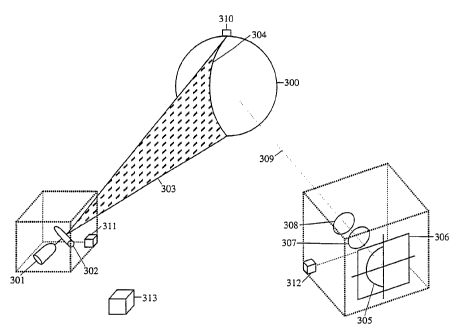
Figure 3: illustrates a perspective view of the system in Figure 1 when used
to scan a spherical object with a fan beam.
Referring to Figure 1, 100 is the object to be scanned. The major
components of the sc~nning system are as follows. An illumination assembly 110
incorporates a low-power laser 101 which is directed through a cylindrical lens
CA 02201107 1997-03-26
W O96/10205 PCTANZ9~/00097
-- 8--
102 thereby generating a fan beam. Other methods of producing a fan beam are
envisged. For example, a point source with a slit aperture and collimator may
produce the desired fan beam. An im~ging assembly 109 incorporates a two-
dimensional (area array) electronic camera 103 which has an optical band-pass
inte.~~ ce filter 104 covering its lens.
The spatial location system comprises a spatial location tr~n~mitter 105
and spatial location receivers 106, 107 and 108.
Spatial location electronics unit 111 and laser line extraction electronics
112 are interfaced to controlling electronics and power supply 113. 114
corresponds to a digital culll~u~
It is considered that an innovative feature enabling the construction of the
truly arbitrary-geometry scanner described herein, resides in the use of spatiallocation devices 105, 106, 107 and 108 to obtain the relative position and
orientalion (6 degrees of freedom) of the object 100, laser(s) 101 and camera(s)103. The spatial location system may correspond to an electronic device such as a
Polhemus 'Fastrak' based on alternating electric fields or an Ascension 'Bird'
based on pulsed static electric fields.
Referring to Figure 1, the dashed boxes 109 and 110 in~ te the
components which are combined into the portable hand-held assemblies each
associated with a spatial location receiver 107 and 108. In this case the im~ging
assembly 109 consists of im~ging components (camera 103 and filter 104) and
spatial location receiver 108. The illumin~tion assembly 110 consists of
illllmin~tion components (laser 101 and cylindrical lens 102) and spatial location
receiver 107.
CA 02201107 1997-03-26
WO 96/10205 PCT/~Z9~l00097
A three-dimensional representation of the system of Figure 1 is shown in
- Figure 3. A cylindrical lens 302 spreads the beam emitted by the laser 301 into
a fan beam 303 so that the intersection between the fan beam and the object being
sc~nnt~l 300 produces a profile 304. The camera includes a lens 307 a CCD array
306 and a filter 308 in front of the camera. The image 305 of the profile 304 isobtained by the camera when viewing the object at an offset angle. The two-
~lim~n.~ional coordinates of the image of the profile are recorded.
The object 300, laser 301 and camera (306 and 307) are associated with
spatial location receivers 310, 311 and 312 respectively thereby allowing their
orientation and location in space to be measured in real time. Thus the laser and
camera may be moved albiLldlily in space so as to record desired profiles
thereby building a reconstructed surface. Alternatively, the object may be movedso as to record the desired profiles.
In use, profiles 304 are recorded by directing the laser fan beam at the
object while .simlllt~n~ously positioning the camera so that the profile is visible to
it. The utility of the present system is illustrated by situations where features of
the object might obscure either the illnmin~tion or the camera's field of view
when using a fixed illnmin~ti~n/im~ging system. If such a geometry is
encountered, the illllmin~tion and/or camera and/or object may be moved into an
orientation or position where the profile is visible to the camera.
The spatial location system 310, 311, 312 and 313 provides the required
spatial location and orientation information for the object, camera and laser
whereupon the three-~iim~n~ional coordinates of the profile are (let~rmin~l fromthe t~,vo-~lim~on~ional pixel coordinates in the camera CCD array 306.
CA 02201107 1997-03-26
W O96/10205 PCTANZ95/00097
- 10-
The scanner may include an hltelr~lcllce filter 308 which allows sc~nning
under ambient light conditions. A further purpose of the interference filter is to
balance the profile contrast as seen by the camera as discussed below.
IllLelrelcnce filters present a lower wavelength pass-band to light from off-
axis and this effect is exploited. The intensity of the profile typically tiimini.~h~s
with tli~t~n~e from its centre. Therefore, if a filter is chosen with a pass-band
centred above the laser wavelength, the distal ends of the laser profile are subject
to less attenuation by the filter. This balances the laser profile contrast as seen by
the camera. Such an application of an inL~lrelcllce filter is, to the applicants'
knowledge, novel.
Referring to Figure 1 the output from each two-dimensional camera 103
(such as a CCD array) is processed a~lo~.liately by line extraction electronics
112 to produce a list of pixels (two-dimensional camera coordinates) at which the
intensity exceeds some threshold (constant or adaptive).
The controlling electronics unit 113 performs such tasks as synchronising
the cameras, lasers and spatial location receivers, monitoring switches, supplying
power, preproce~ing and interfacing this data slream to the digital input/outputport of the host digital cOlll~ul~l 114. The digital co~llL,ul~l is programmed to
reconstruct the three-dimensional coordinates of the object's surface. Such a
reconstruction may employ LLdllsro-lllation methods known in the art which
convert each two-~limen~ional point in the profile, viewed by the camera, to a
three-dimensional point in the camera frame of reference and then to a three-
~limen~ional point in the object frame of reference.
CA 02201107 1997-03-26
wo 96/10205 PCTINZ95100097
- 11 -
The reconstruction process~ must der~ in~ the coordinates of a three-
dimensional point, in the object's fraIne of reference, corresponding to each pixel
identified by the laser line extraction electronics.
This can be accomplished in a number of ways. For example, if a simple
linear model of the camera is assumed, then a ray can be traced from the pixel
location through the centre of the lens whereby the intersection of the ray withthe plane of the laser will determine the three-t1imen.cional coordinate of the
i11umin~ted spot on the object, the camera coordinates and the laser plane having
been transformed into the object's coordinate system using the spatial location
information.
~ 1tern~tively, a 'look-up table' can be used to transform from pixel
coordinates to three-~limen.cional coordinates in the camera frame of reference,and then these coordinates can be transformed into the objects coordinate systemusing the spatial location hlrollllation.
The look-up table can be produced by an empirical calibration process.
Therefore allowances may be made for non-linear effects such as lens distortion
as well as providing for a faster means of data conversion in the co,lll,uL~l.
It will be appreciated that the location of the object being sc~nn~l is
constantly determined by means of the spatial location system. Therefore, so long
as the receiver associated with the object remains in fixed relation to the object,
the object is free to move during the sc~nnin~ process.
It is to be appreciated that both the number of cameras and lasers and/or
the geometry of the system can be varied if desired. If, for example, any two or
CA 02201107 1997-03-26
Wo 96/10205 PC~r/NZss/00097
- 12 -
more components retain a fixed relative spatial relationship throughout the scan,
then the position and orientation of the combined assembly may be recorded by a
single spatial location receiver (the relative locations and orientations of theassembly components being fixed and determined beforehand).
Figure 2 illustrates an embodiment in which the cameras 202 and 203 and
laser 204 are mounted on a hand-held assembly 205 (dotted). In this configuration
the geometrical relationship between the laser fan beam and the cameras are fixed
and known. Accordingly, savings in image processing speed can be effected.
The system shown in Figure 2 is, in most respects, the same as that in
Figure 1 except that additional line extraction electronics 215 are required and a
single spatial location receiver 208 is required for the hand-held assembly 205.
The embodiment shown in Figure 2 is also advantageous in that the
sc~nning assembly is contained in a convenient 'package' or 'wand'. However,
the present invention is not restrictecl to such a construction, and there may be
applications where one or more arbitrarily located cameras and/or lasers are
required.
In the applicants' p~oLoLy~e (which corresponds to the example shown in
Figure 2) a single laser 204 and cylindrical lens 206 is positioned between two
cameras 203 and 202, the laser and cameras being fixed in relation to each otherand mounted on a portable hand-held assembly in-licate(l by the dashed box 205.
The location and orientation of 205 is ~let~rrnin~(l by the spatial location receiver
208. The location of the object 200 is ~te~ Pd by a second spatial location
receiver 201 with the tr~n~mitter 209 fixed in space throughout the scan. Each
camera is s~d~ d from the laser by about 250mm and the optical axis of each
-
CA 02201107 1997-03-26
Wo 96/10205 = PCTJNZ95/Ooos7
- 13 -
carnera is angled to cross t'ne plane of the fan beam at an enclosed angle of about
30 degrees.
In operation, the hand-held unit 205 is directed so that the fan beam
intersects the object 200. Each camera 203 and 202 images the profile at a knownand f~ed offset angle. The profiles are sampled at a rate sufficient so that if the
hand held unit is moved at right angles to the plane of the beam (ie; the laser fan
bearn is swept across the object) the scanned area can be considered as a series of
profiles, each of which is imaged and reconstructed thus forming the scanned
surface.
~ ltern~tively, the spatial location tr~n~mi~ter could be attached directly tO
the object in place of a separate receiver.
In an ~ ive embodiment, the object is held in fixed relation to the
tr~n.~mitter throughout the course of the sc~nnina process. Similarly, any one
component of the sc~nning system itself (camera or laser) may be held stationaryt'nroughout the scan. Its position and orientation is thus an arbitrary constant and
need not be recorded by the spatial location system.
Where in the foregoing description reference has been made to elem~nt~
or integers having known equivalents, then such equivalents are included as if
they were individually set forth.
Although the present invention has been described by way of example and
efe~ ce to particular embodiments, it is to be understood that modifications andimprovements may be made without departing from the scope of the invention as
set out in the appended claims.