Note: Descriptions are shown in the official language in which they were submitted.
W097/05398 PCT~S96/11823
2201 142
-- 1
BALLJO~L~KAND METHODOFPRODUC~GSAME
BACKGROUND OF THE INVENTION
This invention relates to improved ball joint
links that are light in weight and inexpensive to
manufacture, and to methods for forming such links.
Molding techniques in the past have been used
in the fabrication of various ball joint components.
For example, Duncan U.S. Patent No. 3,941,495 teaches a
method for forming a ball around a stud to form a ball
stud.
Sinclair U.S. Patent No. 5,277,860 discloses
an all-plastic rod end in which opposed raceways are
mated to form a socket around a ball. The raceways are
then overmolded to complete fabrication of the rod end.
Memory U.S. Patent 3,591,669 discloses a
plastic universal bearing which is molded in place in a
link. In this case, the plastic that forms the socket
of the ball joint is integral with the plastic that
forms the center section of the link.
Hellon U.S. Patent Application Serial No.
08/253,688, filed June 3, 1994 and assigned to the
assignee of the present invention, discloses an insert
molded ball joint as shown in attached Figure 8. The
ball joint of Hellon includes a housing 100 which is
insert molded around three separate parts: a tubular
center section 102 of a ball joint link, a ball 104 of
a ball stud 106, and a cap 108. A high-strength,
fiber-reinforced plastic is used for the housing 100,
and the same high-strength material that forms the
housing 100 both secures the housing 100 to the center
section 102 and forms the bearing surface for the ball
104. In this way, high pull out forces are required to
dislodge the ball stud 106 from the housing 100.
The present invention differs significantly
from the prior art of Figure 8, particularly with
SUBSnTUTE SHEEr (RULE 26)
W097/0~398 PCT~S96/11823
220 1 1 42
respect to the manner in which the ball stud is
retained in the ball joint, the manner in which the
ball joint socket is formed, and the manner in which
the ball joint is molded.
SUMMARY OF THE INVENTION
According to a first aspect of this
invention, a ball joint link comprises a ball stud and
a strengthening element. The ball stud comprises a
stud which supports a ball, and the strengthening
element is disposed around the ball stud. The
strengthening element comprises a first portion sized
to receive at least part of the ball. A molded body is
formed around part of the ball to form a ball joint.
This body is formed around at least part of the first
portion of the strengthening element to hold the ball
in the ball joint.
According to a second aspect of this
invention, a method for forming a ball joint comprises
the following steps. First, a ball stud and a
strengthening element are positioned in a mold. The
ball stud includes a stud which supports a ball, and
the strengthening element comprises a first portion
receiving at least part of the ball. Then a plastic
material is injected into the mold around the
strengthening element to form a ball joint, such that
the ball and the strengthening element are insert
molded in place in the ball joint.
According to a third aspect of this
invention, a method for forming a ball joint comprises
the following steps. First, a ball stud and a cap are
positioned in a mold. The ball stud comprises a stud
which supports a ball and the cap is supported in the
mold in a desired relationship with respect to the
ball. Then a plastic material is injected into the
mold around the cap to form a body in which
W097/05398 PCT~S96/11823
220 1 1 42
substantially all of the cap is embedded. The body,
ball stud and cap form a ball joint.
The various aspects of this invention are
preferably used together, as described in the following
s detailed description. However, it should be understood
that individual aspects of this invention can be used
independently of one another if desired.
BRIEF DESCRIPTION OF THE DRAWINGS
Figure 1 is a side elevational view of a ball
joint link which incorporates a presently preferred
embodiment of this invention.
Figure 2 is a cross-sectional view of the
ball joint link of Figure 1.
Figure 3 is a perspective view of a
strengthening element shown in Figure 2.
Figure 4 is a side view of the strengthening
element of Figure 3.
Figure 5 is a cross-sectional view taken
along line 5-5 of Figure 4.
Figure 6 is a perspective view of a ball cap
shown in Figure 2.
Figure 7 is a cross-sectional view taken
along line 7-7 of Figure 1, showing portions of a mold
used to form the body 12.
Figure 8 is a cross-sectional view of a prior
art ball joint.
DETAILED DESCRIPTION OF THE PREFERRED EMBODIMENTS
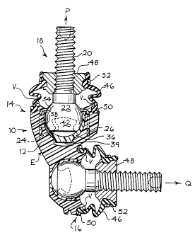
Turning now to the drawings, Figures 1 and 2
show two views of a ball joint link 10 which comprises
a body 12 that forms two ball joints 14, 16. In this
embodiment, the ball joints 14, 16 are oriented at
right angles to one another. It should be understood
that in general the ball joint link 10 can include one
or more ball joints, and if multiple ball joints are
-
W097/05398 PCT~S96/11823
220 1 1 42
provided, they can be oriented at any desired angle
with respect to one another. For example, many ball
joint links include two ball joints oriented with an
included angle of 180 between the ball joints. The
ball joint link 10 can, for example, be adapted for use
with automotive suspension components, such as
stabilizer bar links.
The ball joint 14 includes a ball stud 18
that includes a threaded stud 20 and a ball 22. Many
arrangements are possible for the ball stud 18. For
example, the ball 22 can be formed integrally with the
stud 20, or the ball 22 can be molded in place on the
stud 20. In this embodiment, the ball 22 defines a
non-spherical surface 24 that forms a recess within the
ball 22. Alternately, the end of the ball 22 opposite
the stud 20 can be spherical in shape.
The ball 22 is surrounded by a strengthening
element 26, which is shown in greater detail in Figures
3 through 5. The strengthening element 26 is a
reinforcing element formed of a high-strength material
such as a suitable steel. The strengthening element 26
includes a first portion 28 shaped as an annular flange
that defines an array of through holes 30. The
strengthening element 26 also includes a second portion
32 that extends radially inwardly from the first
portion 28, and that defines an annular surface 34
shaped and positioned to bear on the ball 22. As best
shown in Figure 2, the diameter of the bearing surface
34 can be smaller than the diameter of the ball 22,
such that the ball 22 is prevented from passing through
the strengthening element 26. Alternately, the annular
surface can be sized to allow the ball 22 to pass
through the strengthening element 26.
As shown in Figures 2 and 6, a ball cap 36 is
pivotably mounted on the ball 22. The ball cap 36
defines a bearing surface 38 that receives the ball 22.
W097/05398 2 2 0 1 1 4 2 PCT~S96/11823
The bearing surface 38 forms a ball-receiving recess
that defines a solid angle of at least about a
hemisphere. As shown in Figure 2, the bearing surface
38 extends more than half way around the ball 22, and
the ball cap 36 is held in place on the ball 22 with a
snap fit. If desired, slits 40 (Figure 6) can be
formed on the ball cap 36 to facilitate assembly of the
ball cap 36 on the ball 22. The ball cap 36 can
include an integral protrusion 39.
As best shown in Figure 2, the ball cap 36
cooperates with the ball 22 to form a confined space 42
therebetween. This space 42 can be partially filed
with a lubricant such as a suitable grease.
The ball joint 16 is similar to the ball
joint 14 described above, except that the ball joint 16
does not include a strengthening element. In the
illustrated embodiment, both of the ball joints 14, 16
are formed in a single insert molding operation.
As best shown in Figure 2, each of the ball
joints 14, 16 includes an elastomeric boot 46 and a
threaded nut 48 received on the respective stud. Each
of the boots 46 is secured to the housing 12 by a
retaining ring 50 and to the respective nut 48 by a
retaining ring 52. In the conventional manner, the
region enclosed by the boot 46 can contain a lubricant
such as a suitable grease.
The ball joint link 1~ can be formed
efficiently in an insert molding operation. First the
ball studs are lubricated with a suitable grease that
is held in place by the respective ball caps 36. The
ball caps 36 snap in place on the respective balls,
thereby retaining the grease in place and preventing
plastic from entering the recess in the ball during the
subsequent molding operation. Then the balls, the ball
caps and the strengthening element 26 are positioned
properly inside a mold cavity. Fixtures (not shown in
W097/05398 PCT~S96/11823
- 220 1 1 42
Figure 2) preferably position the strengthening element
26 into contact with the ball 22, as shown in Figure 2.
Alternately, the strengthening element 26 can be
positioned by causing it to bear against the ball cap
36 or the mold surface.
As shown in Figure 7, a mold 60 is used to form
the body 12. This mold 60 comprises two protrusions 62
that are positioned to contact the ball cap 36. These
protrusions 62 perform two functions: they form a stop
for the ball stud/cap combination to locate this
combination properly in the mold; and they prevent the
ball cap 36 from moving away from the ball 22 (Figure
2). In the preferred embodiment, the protrusion 39 of
the ball cap 36 is captured between the protrusions 62
of the mold 60, thereby preventing undesired rotation
of the ball cap 36 on the ball 22 during the molding
operation. After the mold cavity is closed,
thermoplastic material is injected into the mold
cavity. This thermoplastic material substantially
embeds the ball cap 36, and it fills the through holes
30 and the space on both sides of the first portion 28
in order to anchor the strengthening element 26
securely in place in the body 12.
Preferably, the thermoplastic material is a fiber-
reinforced material, and the flow of thermoplastic
material in the mold is arranged to enhance the
strength of the resulting body 12. In this example,
the thermoplastic material is injected into the mold
near point E, and the mold is vented at various points
V (Figure 2). This tends to align the fibers in the
thermoplastic material in a high-strength orientation.
After the thermoplastic material has cooled the mold is
opened and the remaining components of the ball joint
link 10 are assembled. The protrusions 62 of the mold
60 leave indentations in the body 12 that extend
laterally with respect to the stud 20 (Figure 2).
W097/05398 PCT~S96/11823
2201 142
Alternately, the ball cap 36 may be held in
position by rods that extend laterally into the mold
cavity (either transverse or at a predetermined angle
to the axis of the stud). These rods (not shown)
perform the same function as the protrusions 62, but
they can be removed from the mold cavity during the
molding operation to prevent the formation of
indentations in the body 12.
Materials, dimensions, and details of
construction can, of course, be varied to fit the
specific application. The following details of
construction are provided merely to define the
presently preferred embodiment in greater detail, and
are not intended to be limiting. The body 12 can be
formed of a thermoplastic such as 30% glass reinforced
6/6 nylon. DuPont 70G33 has been found suitable. The
strengthening element 26 can be formed of a material
such as 1020 steel, having a wall thickness of about
0.090 inches. The ball caps 36 can be formed of an
acetal material such as that sold under the tradename
Delrin. The ball studs can be formed of 4140 steel,
and the nuts and retaining rings can also be formed of
suitable steel. The boots can be formed of urethane or
rubber.
The ball joint link described above provides
a number of important advantages. First, the
strengthening element is securely anchored in the body,
and the considerable hoop strength of the strengthening
element provides a substantial increase in the strength
of the ball joint link to resist pull out forces
exerted in the direction P. High pull out force
resistance is provided while allowing the use of a ball
cap formed of a material that provides an excellent
bearing surface, and while accommodating a wide angular
range of motion for the ball stud.
W097/05398 PCT~S96/11823
- 2201 142
--8--
Additionally, since the body 12 is insert
molded around the major components of the ball joint,
the assembly is light in weight and relatively
inexpensive to manufacture. Since the end caps snap in
place on the balls of the ball studs, the end caps are
effectively retained in position on the balls during
the molding operation.
In the intended application for the ball
joint link lO, pull out forces along the direction P
are anticipated to be substantially greater than pull
out forces in the direction Q. For this reason, the
ball joint 14 does not require a strengthening element
26 in this application. Of course, it will be
understood that strengthening elements 26 can be
provided on all of the ball joints of the ball joint
link lO if desired.
A wide range of changes and modifications can
be made to the preferred embodiments described above.
For example, the strengthening element 26 described
above can be used without the ball cap 36.
Additionally, materials and configurations can be
adapted as appropriate for the particular application.
Furthermore, it is not required that the first portion
of the strengthening element be annular in
configuration.
It is therefore intended that the foregoing
detailed description be regarded as illustrative rather
than limiting. It is the following claims, including
all equivalents, which are intended to define the scope
of this invention.