Language selection

Search

Patent 2201248 Summary

Third-party information liability

Some of the information on this Web page has been provided by external sources. The Government of Canada is not responsible for the accuracy, reliability or currency of the information supplied by external sources. Users wishing to rely upon this information should consult directly with the source of the information. Content provided by external sources is not subject to official languages, privacy and accessibility requirements.

Claims and Abstract availability

Any discrepancies in the text and image of the Claims and Abstract are due to differing posting times. Text of the Claims and Abstract are posted:

  • At the time the application is open to public inspection;
  • At the time of issue of the patent (grant).
(12) Patent: (11) CA 2201248
(54) English Title: TURF AERATOR ATTACHMENT FOR TRACTOR
(54) French Title: ACCESSOIRE D'AERATION DE GAZON POUR UN TRACTEUR
Status: Deemed expired
Bibliographic Data
(51) International Patent Classification (IPC):
  • A01B 45/02 (2006.01)
(72) Inventors :
  • LECLERC, FRANCOIS (Canada)
(73) Owners :
  • LECLERC, FRANCOIS (Canada)
(71) Applicants :
  • LECLERC, FRANCOIS (Canada)
(74) Agent:
(74) Associate agent:
(45) Issued: 2005-01-11
(22) Filed Date: 1997-03-27
(41) Open to Public Inspection: 1997-09-27
Examination requested: 2002-03-27
Availability of licence: N/A
(25) Language of filing: English

Patent Cooperation Treaty (PCT): No

(30) Application Priority Data:
Application No. Country/Territory Date
60/014,164 United States of America 1996-03-27

Abstracts

English Abstract

An aerator apparatus suitable for use with a tractor, the apparatus comprising a frame and a plurality of aerator disc assemblies. Each aerator disc assembly comprises a plurality of aerator discs and a pair of aerator disc mounting arms extending between the frame and the aerator disc axle. The mounting arms are rotatably journalled on the frame to thereby permit pivotable movement of each of the aerator disc assemblies. Interconnecting means are utilized to interconnect the aerator disc assemblies. The arrangement allows for the turning of the aerator apparatus without damage to the equipment and turf.


French Abstract

Appareil aérateur approprié pour une utilisation avec un tracteur, l'appareil comprenant un cadre et une pluralité d'assemblages de disques d'aérateur. Chaque assemblage de disques d'aérateur comprend une pluralité de disques d'aérateur et une paire de bras de montage de disques d'aérateur s'étendant entre le cadre et l'axe central de disques d'aérateur. Les bras de montage sont montés en rotation sur le cadre pour ainsi permettre un mouvement pivotant de chacun des assemblages de disques d'aérateur. Des moyens de raccordement sont utilisés pour raccorder entre eux les assemblages de disques d'aérateur. L'agencement permet de faire tourner l'appareil aérateur sans endommager l'équipement et l'accessoire.

Claims

Note: Claims are shown in the official language in which they were submitted.


-9-


I CLAIM:

1. An aerator apparatus suitable for use with a
tractor, said apparatus comprising:
a frame,
a plurality of aerator disc assemblies, each aerator
disc assembly comprising a plurality of aerator discs and
aerator disc mounting means, each aerator disc having an
aerator axle, at least one aerator tine extending radially
outward from each of said aerator discs, said aerator disc
mounting means extending between said frame and each of said
aerator axles, said mounting means being rotatably
journalled on said frame to thereby permit pivotable
movement of each of said aerator discs,
and interconnecting means connecting said aerator
disc assemblies.
2. The apparatus of Claim 1 wherein each of said
aerator discs includes a plurality of radially extending
tines.
3. The apparatus of Claim 1 wherein each of said
mounting means comprises a pair of mounting arms, each of
said mounting arms extending between said frame and said
axle, said mounting arms being secured to a shaft, said
shaft being rotatably journalled with respect to said frame.


-10-


4. The apparatus of Claim 1 wherein said
interconnecting means comprises a connecting member
extending between said aerator disc assemblies.
5. The apparatus of Claim 1 further including
attachment means associated with said frame for attaching
said apparatus to a tractor.
6. The apparatus of Claim 1 wherein each of said
mounting means comprises first and second parallel mounting
arms, said first and second parallel mounting arms being
joined together at one end thereof by a first end wall and
at a second end thereof by a second end wall, a shaft
extending between said frame and said first end wall to
permit rotatable movement of said parallel arms with respect
to said frame.

Description

Note: Descriptions are shown in the official language in which they were submitted.


2201248
- 2 -
TURF AERATOR ATTACHMENT FOR TRACTOR
BACKGROUND OF THE INVENTION
The present invention relates to a turf perforating
device or more particularly relates to a turf perforating
device commonly known as an aerator and which is adapted to
be pulled behind a vehicle such as a tractor.
SUMMARY OF THE INVENTION
The use of aerators is well known in the art and
they are used to maintain a healthy vigorous growth of
grass. Aerating devices range from those designed to be used
by the individual homeowner on a relatively small lawn area
to those designed to be pulled behind tractors for larger
areas such as golf courses, parks, athletic fields, and all
other suitable grassy areas.
Aerators generally include a plurality of elements
which are designed to enter the soil as the aerator is
pulled along. This is done for the purpose of pruning root
growth, providing access for air and water to the soil, and
for thatching the existing turf while leaving untouched the
surrounding areas so that normal use of the turf may be
continued.
As aforementioned, there are a number of known
aerators which are adapted to be pulled by a vehicle such as
a tractor and which aerators generally include a plurality
of discs mounted on a shaft. Each of the discs includes a
plurality of elements which are adapted to pierce the soil.


221248
- 3 -
In this respect, there have been several proposals for the
type of element which will pierce the soil; some include a
cylindrical shaped member having a hollow interior such that
plugs are pulled from the soil. These are the so-called
core aerators.
Also known in the art is what is known as a shatter
aerator which does not pull a plug and consequently leaves a
better looking surface. These aerators include specially
shaped tines or spoons which can enter the soil and both
opens and closes the soil to a certain extent.
The problem which has always existed is the use of
the aerators on both uneven ground and the problems for
following an irregular course - i.e. one in which turning is
required. Thus, the conventional arrangement is one wherein
all the discs are mounted on a single shaft and the amount
of turning must be minimized to avoid substantial damage to
the grounds and/or the equipment itself.
It is therefore an object of the present invention
to provide an aerator of the type to be pulled or pushed by
a vehicle such as a tractor and which aerator can follow
other than a straight line without damage to the equipment
and/or turf.
It is a further object of the present invention to
provide an aerator attachment for a tractor and which
aerator attachment can be designed to either be pushed ahead
of a tractor or be towed thereby.


2201248
- 4 -
According to one aspect of the present invention,
there is provided an aerator apparatus suitable for use with
a tractor, the apparatus comprising a frame, a plurality of
aerator disc assemblies, each aerator disc assembly
comprising a plurality of aerator discs and aerator disc
mounting means, each aerator disc having an aerator axle, at
least one aerator tine extending radially outward from each
of the aerator discs, the aerator disc mounting means
extending between the frame and each of the aerator axles,
the mounting means being rotatably journalled on the frame
to thereby permit pivotable movement of each of the aerator
discs, and interconnecting means connecting the aerator
disc assemblies.
In greater detail, the aerator apparatus of the
present invention can, as aforementioned, either be towed
behind a tractor or mounted on the front of tractors which
are designed to accept such equipment. The means for
attaching the aerator apparatus to the tractor may be any
conventional including a draw bar, three point attachment,
etc. It suffices to say that most tractor manufacturers
have a standard attachment means.
Each aerator disc assembly of the present invention
includes an aerator disc having at least one aerator tine
extending radially outwardly therefrom. This is a
conventional arrangement and the tines may be of the type
adapted to remove a plug or it may be of the type known as a
shatter aerator tine or spoon which enters the soil and both


22~124g
- 5 -
opens and closes the soil. The number of tines extending
radially outwardly from the disc may be varied and would
typically range from between 6 and 12 times per aerator
disc.
Each aerator disc has an axle associated therewith
and mounting means are utilized to connect between the ends
of each axle to the frame. The mounting means are rotatably
journalled or mounted such that each mounting means and
associated aerator disc with which together comprise the
aerator disc assembly can pivot or rotate. The connection
between the frame and the mounting members can be any
conventional arrangement.
BRIEF DESCRIPTION OF THE DRAWINGS
Having thus generally described the invention,
reference will be made to the accompanying drawings
illustrating an embodiment thereof, in which:
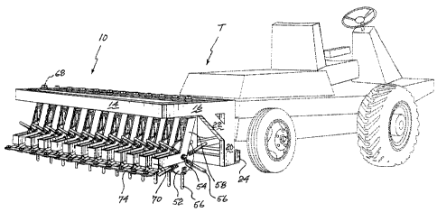
Figure 1 is a perspective view of a tractor and
aerator apparatus according to the present invention;
Figure 2 is a rear elevational view of the aerator
apparatus;
Figure 3 is a side view of the aerator apparatus;
Figure 4 is a top plan view of the aerator
apparatus;
Figure 5 is a side elevational view showing one
means of attachment of the aerator apparatus to a tractor;
and


221248
- 6 -
Figure 6 is a top plan view similar to Figure 4
illustrating the pivotatable or rotatable movement of the
aerator disc assemblies.
DESCRIPTION OF THE PREFERRED EMBODIMENTS
Referring to the drawings in greater detail and by
reference characters thereto, the illustrated embodiment
shows an aerator apparatus generally designated by reference
numeral 10 and which aerator apparatus 10 is designed to be
operated in conjunction with a tractor T.
Aerator apparatus 10 has an upper frame assembly
comprising a pair of side frame members 12 and 14 and a pair
of end frame members 16 and 18. As may be seen in Figure 1
and 3, a vertical frame member 20 extends downwardly from
the junction of side frame member 12 and end frame member
16. A reinforcing frame element 22 extends between end
frame member 16 and vertical frame member 20. A similar
arrangement (not shown), is provided on the other side at
the point of juncture of side frame member 12 and end frame
member 18. At the lower extremity of vertical frame member
20 there is provided a bottom horizontal frame member 24.
Bottom horizontal frame member 24 carry first and
second lower attachment means 26 and 32 respectively. Lower
attachment means 26 comprises a pair of outwardly extending
plates 28 and 30 while lower attachment means 32 also
includes outwardly extending plates 34 and 36. Mounted on
side frame member 12 is a upper attachment means generally


Zzo ~ 24a
_ 7 _
designated by reference numeral 38 and which comprises
outwardly extending plates 40 and 42.
Extending between end frame members 16 and 18 and in
a generally parallel relationship with side frame members 12
and 14 are a pair of horizontal mounting bars 44 and 46
(Figures 4 and 6). A plurality of frame elements 50
extend between horizontal mounting bar 44 and side frame
member 12 and also between horizontal mounting bar 46 and
side frame member 14. A metal mesh 48 covers the top
portion of the apparatus.
Aerator apparatus 10 includes a plurality of aerator
discs 52 mounted in a side by side arrangement with each
disc including an axle 54 and having tines 56 extending
radially therefrom. Each disc 52 has mounting means
associated therewith, the mounting means comprising a pair
of parallel mounting arms 58 and 60 which, at their upper
end, have a pair of horizontal elements 62 and 64 extending
therebetween. The arrangement is such to receive a shaft 66
which is retained by means of shaft retaining nut 68.
At their lower extremity, mounting arms 58 and 60
are interconnected by an end wall 70 which in turn has a
bracket 72 extending therefrom.
Brackets 72 are interconnected by horizontal
interconnecting member 74 by a nut a bolt arrangement 76.
The arrangement is such that when towed or pushed,
each mounting means is pivotable or rotatable due to the
rotatable mounting of shaft 66. Interconnecting member 74


2201248
_8_
ensures that all discs 52 turn simultaneously as indicated
by arrows 78 (Figure 6).
As aforementioned, the attachment by means of a pair
of lower attachment means 26 and 32 is substantially
conventional while upper attachment means 38 may be designed
to receive a chain 80 for further attachment to the
tractor T.
It will be understood that the above described
embodiment is for purposes of illustration only and that
changes and modifications may be made thereto without the
departing from the spirit and scope of the invention.

Representative Drawing
A single figure which represents the drawing illustrating the invention.
Administrative Status

For a clearer understanding of the status of the application/patent presented on this page, the site Disclaimer , as well as the definitions for Patent , Administrative Status , Maintenance Fee  and Payment History  should be consulted.

Administrative Status

Title Date
Forecasted Issue Date 2005-01-11
(22) Filed 1997-03-27
(41) Open to Public Inspection 1997-09-27
Examination Requested 2002-03-27
(45) Issued 2005-01-11
Deemed Expired 2014-03-27

Abandonment History

There is no abandonment history.

Payment History

Fee Type Anniversary Year Due Date Amount Paid Paid Date
Application Fee $150.00 1997-03-27
Maintenance Fee - Application - New Act 2 1999-03-29 $50.00 1999-03-16
Maintenance Fee - Application - New Act 3 2000-03-27 $50.00 2000-03-17
Maintenance Fee - Application - New Act 4 2001-03-27 $50.00 2001-03-27
Request for Examination $200.00 2002-03-27
Maintenance Fee - Application - New Act 5 2002-03-27 $75.00 2002-03-27
Maintenance Fee - Application - New Act 6 2003-03-27 $75.00 2003-03-24
Maintenance Fee - Application - New Act 7 2004-03-29 $100.00 2004-03-04
Final Fee $150.00 2004-10-14
Maintenance Fee - Patent - New Act 8 2005-03-29 $100.00 2005-03-08
Maintenance Fee - Patent - New Act 9 2006-03-27 $100.00 2006-03-06
Maintenance Fee - Patent - New Act 10 2007-03-27 $125.00 2007-03-16
Maintenance Fee - Patent - New Act 11 2008-03-27 $125.00 2008-03-19
Maintenance Fee - Patent - New Act 12 2009-03-27 $125.00 2009-03-20
Maintenance Fee - Patent - New Act 13 2010-03-29 $125.00 2010-03-02
Maintenance Fee - Patent - New Act 14 2011-03-28 $125.00 2011-02-28
Maintenance Fee - Patent - New Act 15 2012-03-27 $225.00 2012-03-09
Owners on Record

Note: Records showing the ownership history in alphabetical order.

Current Owners on Record
LECLERC, FRANCOIS
Past Owners on Record
None
Past Owners that do not appear in the "Owners on Record" listing will appear in other documentation within the application.
Documents

To view selected files, please enter reCAPTCHA code :


To view images, click a link in the Document Description column. To download the documents, select one or more checkboxes in the first column and then click the "Download Selected in PDF format (Zip Archive)" or the "Download Selected as Single PDF" button.

List of published and non-published patent-specific documents on the CPD .

If you have any difficulty accessing content, you can call the Client Service Centre at 1-866-997-1936 or send them an e-mail at CIPO Client Service Centre.


Document
Description 
Date
(yyyy-mm-dd) 
Number of pages   Size of Image (KB) 
Drawings 1997-03-27 3 155
Representative Drawing 1999-09-28 1 21
Abstract 1997-03-27 1 18
Description 1997-03-27 7 233
Claims 1997-03-27 2 48
Cover Page 1999-11-02 1 42
Representative Drawing 2004-12-07 1 25
Cover Page 2004-12-07 1 53
Assignment 1997-03-27 3 105
Prosecution-Amendment 2002-03-27 1 23
Fees 2003-03-24 1 25
Correspondence 2004-10-14 1 27
Fees 1999-03-17 1 28
Fees 2001-03-27 1 25
Fees 2002-03-27 1 26
Fees 2000-03-17 1 25
Fees 2004-03-04 1 23
Fees 2005-03-08 1 21
Fees 2006-03-06 1 20