Language selection

Search

Patent 2201517 Summary

Third-party information liability

Some of the information on this Web page has been provided by external sources. The Government of Canada is not responsible for the accuracy, reliability or currency of the information supplied by external sources. Users wishing to rely upon this information should consult directly with the source of the information. Content provided by external sources is not subject to official languages, privacy and accessibility requirements.

Claims and Abstract availability

Any discrepancies in the text and image of the Claims and Abstract are due to differing posting times. Text of the Claims and Abstract are posted:

  • At the time the application is open to public inspection;
  • At the time of issue of the patent (grant).
(12) Patent: (11) CA 2201517
(54) English Title: A DEVICE FOR BURNING GAS FROM A PRODUCTION PLANT FOR OIL OR GAS
(54) French Title: DISPOSITIF SERVANT A BRULER LE GAZ A LA SORTIE D'UNE INSTALLATION DE PRODUCTION DE PETROLE OU DE GAZ
Status: Term Expired - Post Grant Beyond Limit
Bibliographic Data
(51) International Patent Classification (IPC):
  • F23G 07/08 (2006.01)
  • F23K 05/00 (2006.01)
(72) Inventors :
  • HYSTAD, HARALD (DECEASED) (Norway)
(73) Owners :
  • ANNE ELISE LEGAL REPRESENTATIVE OF HARALD HYSTAD HYSTAD
(71) Applicants :
  • ANNE ELISE LEGAL REPRESENTATIVE OF HARALD HYSTAD HYSTAD (Norway)
(74) Agent: SMART & BIGGAR LP
(74) Associate agent:
(45) Issued: 2000-07-25
(86) PCT Filing Date: 1995-10-02
(87) Open to Public Inspection: 1996-04-11
Examination requested: 1997-04-01
Availability of licence: N/A
Dedicated to the Public: N/A
(25) Language of filing: English

Patent Cooperation Treaty (PCT): Yes
(86) PCT Filing Number: PCT/NO1995/000175
(87) International Publication Number: NO1995000175
(85) National Entry: 1997-04-01

(30) Application Priority Data:
Application No. Country/Territory Date
943680 (Norway) 1994-10-03

Abstracts

English Abstract


A device for burning gas from a production plant for oil/gas comprising a
burner at the top of a flare pipe (8). The production plant is connected to
the flare pipe (8) through a low pressure collection line (1) for process gas.
One has aimed at reducing combustion of valuable production gas to a minimum.
To this end, the collection line (1) is connected to an expansion tank (2)
having a return line (4) to the production plant and, downstream relative to
the expansion tank (2), a liquid trap (6) has been disposed.


French Abstract

Dispositif servant à brûler le gaz à la sortie d'une installation de production de pétrole ou de gaz, et comportant un brûleur monté à l'extrémité supérieure d'une conduite de torchage (8). L'installation de production est reliée à la conduite de torchage (8) par l'intermédiaire d'un tuyau collecteur à basse pression (1) pour le gaz produit. On a cherché à minimiser la combustion du précieux gaz de production. A cette fin, le tuyau collecteur (1) est relié à un réservoir de détente (2) possédant un tuyau de retour (4) vers l'installation de production, et un piège à liquide (6) est monté en aval par rapport au réservoir de détente (2).

Claims

Note: Claims are shown in the official language in which they were submitted.

6
CLAIMS
1. A device for burning gas from a production plant for
oil/gas, comprising a flare burner at the top of a
flare pipe (8), raid production plant being connected
to said flare pipe (8) through a low pressure
collection line (1) for process gas, a liquid trap (6)
being positioned between said production plant and said
flare pipe (8), characterized in that
said low pressure collection line is connected to a
tank (2) having a return line (4) to said production
plant, said liquid trap (6) being positioned between
said tank (2) and said flare pipe (8).
2. A device as sect forth in claim 1,
characterized in that said liquid trap
(6) is formed from an upwardly concave pipe bend which,
at one end thereof, is connected to a downwardly
directed pipeline portion included in a pipeline
extending between said tank (2) and said liquid trap
(6) and which, at the other end thereof, is connected
to said flare pipe (8) through the intermediary of a
flare pipe pot (7).
3. A device as set forth in claim 1,
characterized in that said liquid trap
(6) is connected to a liquid reservoir (12), to a level
controller (13) as well as to a non-return valve (17)
disposed in a connection line (16) extending between
said liquid reservoir (12) and said liquid trap (6).

7
4. A device as set forth in claim 1,
characterized in that said tank (2) is
connected to a compressor (3) connected to said
production plant and adapted to establish and maintain
an underpressure within said tank (2), and that said
flare burner at the top of said flare pipe (8) is
connected to a separate fuel supply pipe (9).
5. A device as set forth in claim 2,
characterized in that said flare pipe
pot (7) internally has one or more guide/barrier plates
(18, 18') having a vertically through-going aperture
(19, 19').

Description

Note: Descriptions are shown in the official language in which they were submitted.


~~A~~~ 7
WO 96/10719 PCT/N095/00175
1
A device for burning gas from a production plant for
oil or gas.
The invention relates to a device for burning gas in oil/
gas production, wherein the production plant is assigned
a burner through a low pressure collection conduit for
process gas.
Gas escaping a production plant for oil/gas constitutes
an explosion risk and is, consequently, burned before the
combustion products are released iW;:o thc~ atmos phere.
In order that sudden and unintentional discharges of gas
could be burned in the burner, the latter has to be ignited
at all times. This involves the necessity of supplying the
burner with gas continuously.
Burning gas pollutes the atmosphere and gives an increased
discharge of COZ ~ Moreover, in order to maintain the
ermanent flame, one has to burn gas that otherwise might have
been sold and it is, therefore, connected with substantial
costs to keep the burner continuously in operation with a
view to a possible future unintentional discharge of gas.
Consequently, the object of the invention has been to
provide a device for burning gas in accordance with the
introduction section, Wherein burning of valuable production
gas has been kept at a minimum level.
According to the invention, this object is realized through

CA 02201517 1999-09-09
2
the provision of a device for burning gas from an
oil/gas production plant comprising a flare burner at
the top of a flare pipe connected to the production
plant through a low-pressure collection line for
process gas, a :Liquid trap being positioned between the
production plants and the flare pipe. The device is
particularly ch<~racterized in that the aforementioned
low-pressure co:Llection line is connected to a tank
which has a return line to the production plant, the
liquid trap being positioned between the tank and the
flare pipe.
A process plant to which the device according to the
invention should be assigned, is in known manner
connected to a collection line for surplus gas. This
collection line is assigned a tank (expansion tank) in
which an underpressure is maintained, a compressor
carrying surplu:~ gas from the tank and back into the
process. The tank is connected to a flare burner
through a liquid trap preventing the compressor to suck
false air.
Thus, according to an important feature of the
invention, the burner is connected to an expansion tank
through a liquid trap.
According to another important feature of the
invention, the 7_iquid trap is assigned a liquid
reservoir and a level controller adapted to influence
the liquid resex-voir in order to replace possible loss
of liquid in the' liquid trap.
Advantageously, the liquid trap may be assigned a non-
return valve adapted to prevent gas from penetrating
into said liquid reservoir.
A flare pipe pot: may be disposed downstream relative to

CA 02201517 1999-09-09
2a
the liquid trap, and said pot may be provided with at
least one later<~1 guide/barrier plate preventing trap
liquid from the liquid trap from being hurled up into
the flare pipe :Leading to the burner which is located
at the uppermost. level.
Upon sudden discharge of gas, the pressure within the
expansion tank increases, whereupon liquid from the
liquid trap is hurled up into said flare pipe pot and,
thus, gives a free passage for gas to the burner.

WO 96/10719 'Z ~ p 7 PCT/N095/00175
According to a subordinate feature of the invention, the
burner is continuously driven with pilot gas, such that
a permanent pilot flame is being maintained. Thus, the
burner is assigned a pilot gas reservoir for controlled
supply of pilot gas to the burner. Such a controlled
combustion of pilot gas represents only insignificant
costs as compared with the excessive combustion of process
gas taking place at known and conventional process plants,
and which has been further accounted for introductorily.
Further objects, features and advantages of the invention
appear from the following description of an examplary
embodiment which is diagrammatically illustrated on the
attached drawings, wherein:
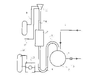
Figure 1 shows the process plant's collection line and
burner as well as intermediate equipment components in
sides elevational view/axial section;
Figure 2 shows in perspective the expansion tank and the
flare pipe pot and intermediate components;
Figure 3 shows a vertical cross-sectional view through
the flare pipe pot separately.
In the drawings, figure 1, reference numeral 1 denotes a
collection line for surplus gas and smaller gas discharges,
assigned a process plant not further shown.
The collection line 1 leads to an expansion tank 2 (a tank
which accommodating change of volume) operating at
underpressure and which, to this end, is connected to a
compressor 3 adapted to carry gas from the tank 2 back
into the process again through a pipeline 4.
Through a short pipeline 5, the expansion tank 2 is
connected to a liquid trap 6 which, at the downstream end
thereof, is connected to a flare pipe pot 7. The flare

WO 96110719 ~ ~ PCT/N095100175
4
pipe which uppermost carries a burner known per se (not
further shown in figure 1), is generally denoted at
reference numeral 8.
In order to maintain a permanent pilot flame which is
independent on the supply of excess gas from the process
plant, the burner is supplied with fuel gas and air through
pipelines 9 and 10, respectively. The pilot burner at the
top of the flare pipe 8 is assigned a cap in order to
maintain good combustion conditions.
In order to replace possibly lost liquid trap liquid, a
liquid reservoir 12 has been disposed, the liquid trap 6
being assigned a level controller 13 which is coupled to the
liquid reservoir 12 for - upon falling liquid surface within
the liquid trap 6 - to cause the reservoir 12 to supply
thereto an amount of liquid corresponding to the one lost.
according to figure 2, the liquid reservoir 12 has been
assigned a liquid pump 14 and a venting pipe 15, a non-return
valve 17 being disposed in a connection line 16 between
liquid reservoir 12 and liquid trap 6, and adapted to prevent
gas from penetrating into the liquid reservoir 12.
In the example, in accordance with figure 3, the flare pipe
pot 7 is equipped with two internal, parallel guide/barrier
plates 18, 18', each having a through-going, central hole 19,
19'. The plates 18, 18' shall prevent liquid from being
hurled up into the flare pipe 8 leading to the burner.
During normal operation, excess gas and smaller discharges
of gas are conducted to the expansion tank 2 in order to have
the pressure reduced. The compressor 3 carries gas from the
tank 2 back into the process again through the pipeline 4. If
the discharge is so large that the pressure within the
expansion tank 2 exceeds a predetermined value given by
the liquid column in the liquid trap 6, the liquid trap
6 opens, liquid being hurled up into the flare pipe pot 7,

WO 96/10719 ~ ~ ~ ~ PCT/N095l00175
where the liquid is spread, so that gas may pass. When the
pressure within and the gas flow through the expansion tank
are reduced, liquid trap liquid from the flare pipe pot 7
will flow back into the liquid trap 6, which is formed by a
downwardly convex pipe bend (6). A possible loss of liquid
in the liquid trap 6, is replaced from the liquid reservoir
12 through the level controller 13.

Representative Drawing
A single figure which represents the drawing illustrating the invention.
Administrative Status

2024-08-01:As part of the Next Generation Patents (NGP) transition, the Canadian Patents Database (CPD) now contains a more detailed Event History, which replicates the Event Log of our new back-office solution.

Please note that "Inactive:" events refers to events no longer in use in our new back-office solution.

For a clearer understanding of the status of the application/patent presented on this page, the site Disclaimer , as well as the definitions for Patent , Event History , Maintenance Fee  and Payment History  should be consulted.

Event History

Description Date
Inactive: Expired (new Act pat) 2015-10-02
Inactive: Late MF processed 2009-11-17
Letter Sent 2009-10-02
Letter Sent 2007-05-28
Inactive: Office letter 2006-12-12
Inactive: Entity size changed 2006-12-06
Inactive: Corrective payment - s.78.6 Act 2006-11-20
Grant by Issuance 2000-07-25
Inactive: Cover page published 2000-07-24
Pre-grant 2000-04-18
Inactive: Final fee received 2000-04-18
Notice of Allowance is Issued 1999-12-07
Letter Sent 1999-12-07
Inactive: Approved for allowance (AFA) 1999-10-29
Amendment Received - Voluntary Amendment 1999-09-09
Inactive: S.30(2) Rules - Examiner requisition 1999-06-02
Inactive: IPC assigned 1997-07-10
Inactive: First IPC assigned 1997-07-10
Inactive: IPC assigned 1997-07-10
Letter Sent 1997-07-02
Inactive: Acknowledgment of national entry - RFE 1997-06-27
Inactive: Applicant deleted 1997-06-27
All Requirements for Examination Determined Compliant 1997-04-01
Request for Examination Requirements Determined Compliant 1997-04-01
Application Published (Open to Public Inspection) 1996-04-11

Abandonment History

There is no abandonment history.

Maintenance Fee

The last payment was received on 1999-09-13

Note : If the full payment has not been received on or before the date indicated, a further fee may be required which may be one of the following

  • the reinstatement fee;
  • the late payment fee; or
  • additional fee to reverse deemed expiry.

Patent fees are adjusted on the 1st of January every year. The amounts above are the current amounts if received by December 31 of the current year.
Please refer to the CIPO Patent Fees web page to see all current fee amounts.

Owners on Record

Note: Records showing the ownership history in alphabetical order.

Current Owners on Record
ANNE ELISE LEGAL REPRESENTATIVE OF HARALD HYSTAD HYSTAD
Past Owners on Record
HARALD (DECEASED) HYSTAD
Past Owners that do not appear in the "Owners on Record" listing will appear in other documentation within the application.
Documents

To view selected files, please enter reCAPTCHA code :


To view images, click a link in the Document Description column. To download the documents, select one or more checkboxes in the first column and then click the "Download Selected in PDF format (Zip Archive)" or the "Download Selected as Single PDF" button.

List of published and non-published patent-specific documents on the CPD .

If you have any difficulty accessing content, you can call the Client Service Centre at 1-866-997-1936 or send them an e-mail at CIPO Client Service Centre.


Document
Description 
Date
(yyyy-mm-dd) 
Number of pages   Size of Image (KB) 
Abstract 1997-03-31 1 46
Description 1997-03-31 5 181
Claims 1997-03-31 2 72
Drawings 1997-03-31 3 33
Description 1999-09-08 6 193
Claims 1999-09-08 2 49
Representative drawing 2000-07-05 1 5
Notice of National Entry 1997-06-26 1 202
Courtesy - Certificate of registration (related document(s)) 1997-07-01 1 118
Commissioner's Notice - Application Found Allowable 1999-12-06 1 164
Maintenance Fee Notice 2009-11-15 1 170
Late Payment Acknowledgement 2009-12-01 1 163
Fees 2003-08-24 1 30
PCT 1997-03-31 12 431
Correspondence 2000-04-17 1 45
Fees 1998-09-07 1 37
Fees 2000-08-28 1 30
Fees 2002-08-25 1 32
Fees 2001-09-03 1 33
Fees 1997-09-28 1 30
Fees 1999-09-12 1 26
Fees 2004-08-19 1 30
Fees 2005-08-18 1 28
Fees 2006-08-21 1 28
Fees 2006-11-19 2 56
Correspondence 2006-12-11 1 28
Correspondence 2007-05-27 1 14
Correspondence 2007-01-25 1 28
Fees 2006-11-19 2 65
Fees 2007-08-21 1 30
Fees 2008-08-19 1 35
Fees 2009-11-16 1 33
Fees 2009-11-16 1 34