Note: Descriptions are shown in the official language in which they were submitted.
2 2 0 1 5 4 7
TRANSPORT APPARATUS FOR VERTICALLY MO~ OBJECTS AND METHOD
Field of the Invention
The Invention relates to transport apparatus for
repetitively moving objects between a number of vertically
spaced transport positions. The invention is used on assembly
lines to keep assembly line workers stocked with the necessary
work parts which are attached to assemblies moving along the
line.
Description of the Prior Art
Parts are conventionally supplied to assembly line workers
on pallets which are stored in two level and three-level pallet
racks located on one side of the line adjacent a work station.
These racks are relatively narrow, given the close spacing of
work stations along the line. The worker picks parts from the
pallet at the bottom of the rack and places the parts on
assemblies moving along the line. Pallets loaded with parts are
placed on the rack at the upper two levels in order to assure
that a supply of parts is maintained adjacent the work station
for transfer to the lower level when parts are exhausted from
the pallet at the lower level.
Loaded pallets on the racks are moved to different
positions in the rack using a fork lift truck which is driven
along a roadway extending along the side of the racks away from
the assembly line. The fork lift trucks load filled pallets in
the upper two levels on the rack and, in response to requests
from workers, remove empty pallets from the bottom level of the
2 20 1 54Z
rack and then pick up a full pallet from one of the upper levels
and move the pallet to the bottom level. It is essential that
these operations be performed promptly in order to assure that
the workers always have a supply of parts. If a work station
runs out of parts the assembly line must be shut down until
parts are resupplied to the station.
The worker is unable to transfer a loaded pallet on the
rack to the bottom station but must await the arrival of a fork
lift truck to perform this operation. There can be a
considerable delay between the time a worker signals that the
pallet at the lower work level is empty and an available lift
truck can be driven to the opposite side of the rack for removal
of the empty pallet and movement of a loaded pallet at an upper
down to the lower level. The job of supplying work parts
to assembly line workers is further complicated because the
number of parts carried by a single pallet may vary depending
upon the size or weight of the part. This means that there is
a greater call for fork lift trucks to service the work stations
with pallets carrying a small number of parts than there is for
work stations with pallets carrying a larger number of parts.
The problem of supplying work parts to assembly line work
stations is further complicated because the work stations are
closely spaced together along the length of the line. Parts
must be stored above the lower level in pallet racks because
there is no available space to either side of the work station.
All of these factors complicate the supply of pallets with
work parts to assembly line workers, particularly in assembly
220 1547
lines where the delay or misplacement of a single pallet of
critical parts could delay or stop production on the entire
line. Shutdown of an assembly line of this type because of a
lack of work parts is very expensive.
Summary of the Invention
The invention is a transport apparatus useful on an
assembly line for on-demand delivery of loaded pallets to a
bottom work position. The apparatus includes a vertically
extending frame, a transport column in the frame, a number of
vertically movable plate assemblies mounted on the frame and a
number of assembly drives connected to the plate assemblies for
moving the assemblies up and down the frame.
The frame has an operator side with a work part discharge
opening that provides worker access to work parts on a pallet at
the bottom work position and an opposed loading side that
provides fork lift truck access to the bottom work position and
to two elevated storage positions.
The plate assemblies each include a carriage mounted on the
frame, a pallet support plate, a hinge connection between the
carriage and the support plate and a hinge drive. The hinge
drive rotates the plate from a horizontal load-supporting
position in the transport column to a retracted vertical
position outside the column close to the frame. The assembly
drive lowers plate assemblies with horizontal plates carrying
loaded pallets down to the bottom work position to supply parts
to an assembly line worker on demand.
When all the work parts have been removed from the pallet
at the work position, the worker pushes the empty pallet from
- 2 2 0 1 5 ~ 7
--4--
the work position and actuates the transport apparatus to
automatically rotate the empty lower plate to a vertical
position at one side of the column and then lower an elevated
plate assembly carrying a loaded pallet down the column, past
the vertical plate and to the work position to resupply parts to
the lower or bottom position. The plate assembly with the
vertical plate is raised past the new assembly at the lower
position to an elevated position and the vertical plate is then
returned to the horizontal to receive a loaded pallet from a
supply fork lift truck.
The transport apparatus moves loaded pallets from an
elevated storage position down to the bottom work position upon
worker demand. The transfer of a loaded pallet down to the work
position is made automatically and rapidly without the need to
position a fork lift truck at the back of the frame, lift a
loaded pallet from an upper storage position, withdraw the
lifted pallet from the frame, lower the pallet on the truck to
the bottom position and then move the pallet into the frame and
place the pallet in the lower position. On-demand delivery of
loaded pallets to the work position reduces assembly line
downtime due to a lack of parts.
The transport apparatus is compact with all plate
assemblies and associated drives located within the space
occupied by a conventional three level or tier pallet frame.
The compact design is important because there is very limited
space available for pallet storage to one side of a production
line.
r 2 20 1 5 6~ 7
-5-
Other objects and features of the invention will become
apparent as the description proceeds, especially when taken in
conjunction with the accompanying drawings illustrating the
invention, of which there are sixteen sheets and one embodiment.
Description of the Drawings
Figure 1 is a perspective view of the apparatus according
to the invention taken from one side;
Figure 2 is a perspective view similar to Fig. 1 taken from
the opposite side;
Figures 3 and 4 are partial perspective views of a plate
assembly taken from opposite sides;
Figure 5 is a side view of the plate assembly of Figs. 3
and 4;
Figures 6 and 7 are partial perspective views of a plate
assembly with an elongate carriage;
Figures 8 and 9 are perspective views of the plate assembly
of Figs. 6 and 7 in a retracted vertical position;
Figure 10 is a side view of a plate assembly similar to
Figs. 6 and 7;
Figure 11 is a sectional view of the apparatus taken along
line 11 -- 11 of Fig. l;
Figure 12 is a sectional view similar to Fig. 11 taken
along line 12 -- 12 of Fig. l;
Figure 13 is a perspective view of an assembly drive; and
Figures 14A and 14B - 25A and 25B are paired views of the
apparatus in different positions illustrating one cycle of
operation from the operator side and the right side.
1 220 15~7
--6--
Description of the Preferred Embodiment
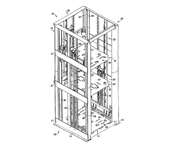
As illustrated in Figs. 1 and 2, transport apparatus 10
includes a rectangular vertically extending frame 12, three
plate assemblies 14, 16 and 18 mounted on the frame 12 and three
assembly drives 20, 22 and 24 connected respectively to
assemblies 14, 16 and 18 for moving the plate assemblies
vertically along frame 12.
Frame 12 includes a right side 26, a left side 28, an
operator side 30 and a loading side 32 each extending from frame
base 34 to top 36. Frame 12 surrounds and defines vertical
transport column 38. Transport column 38 includes a bottom work
position 40 adjacent base 34, a middle storage position 42
spaced above bottom work position 40 and a top storage position
44 spaced above middle storage position 42 and below top 36.
Like assembly drives 20 and 22 move like plate assemblies
14 and 16 up and down along transport column 38 between bottom
work position 40, middle storage position 42 and top storage
position 44. Assembly drive 24 moves plate assembly 18 up and
down between bottom work position 40 and middle storage position
42.
Frame 12 includes four elongate corner posts 46 extending
from base 34 to top 36, a number of cross members 47 between the
posts, and three pairs of opposed vertical U-channels 48, 50 and
52 at the edges of right side 26, left side 28 and operator side
30, respectively. Each U-channel is joined to and extends the
full height of frame 12 along one of posts 46.
As shown in Figs. 3-5, plate assembly 14 includes a
vertically moveable carriage 56 extending across side 26 between
2~0 ~54~
adjacent pair of U-channels 48, a rectangular plate 58, a
horizontal hinge 60 joining plate 58 to carriage 56 and a pair
of fluid cylinder hinge drives 62 and 64 mounted on carriage 56
and operable to rotate plate 58 between a horizontal load
5 supporting position in column 38 and a vertical position
adjacent the frame and to one side of the column.
Two spaced carriage wheels 66, 68 and 70, 72 are mounted on
each opposed end of carriage 56. The wheels run in U-channels
48 to facilitate vertical movement of carriage 56 on the frame.
The axis of hinge 60 extends horizontally across the right side
26 of frame 12 and along the carriage 56, to one side of
transport column 38. Cylinder drives 62 and 64 connect the
plate and carriage a distance outwardly from the hinge to rotate
the plate relative to the carriage as described. The drives 62
15 and 64 are located at the ends of the hinge 60 and do not
obstruct the load supporting surface of the plate 58 in column
38. Stops on the carriage 56 support the plate when in the
horizontal position. When the plate is in the vertical
position, the assembly drive 20 may move plate assembly 14
vertically past the other plate assemblies 16 and 18. Pairs of
spaced guide rails 74 are mounted on frame 12 right and left
sides 26 and 28 and extend vertically from the base 34 to top 36
of the frame.
Assembly drive 20 includes a hydraulic cylinder 76 having
25 a body mounted on the base 34 between pair of guide rails 74 and
a piston rod 78 extending vertically from the body to a lift
head 80 on the end of the rod. A pair of idler sprocket gears
82 are mounted on head 80. Assembly drive 20 also includes two
2 2 0 ~ 5 4 7
--8--
like lift chains 84. One end of each chain is secured to a
cross member 47 at bottom of the frame. The chains extend up
from the cross member, are wrapped around gears 82 on head 80
and extend down from the gears to second ends secured to
carriage 56 of plate assembly 14. Extension and retraction of
cylinder 76 moves assembly 14 between the bottom, middle and top
positions in column 38. Pairs of guide wheels 86 and 88 on head
80 are located to either side of rails 74 and hold the head in
place between the rails during raising and lowering of assembly
14. Assembly drive 20 is located entirely within the frame 12.
The drive rapidly raises and lowers plate assembly 14 at twice
the extension and retraction speed of cylinder 76.
Assembly drive Z2 for plate assembly 16 is identical to
assembly drive 20 and need not be further described.
As shown in Figs. 3-5, hinge 60 includes a number of plate
ribs 90, 92, 94, 96, 98 and 100 mounted on the bottom of plate
58, a number of carriage ribs 102 mounted on carriage 56 and a
hinge pin 104 extending through bores in the free ends of the
ribs. Hinge drive cylinders 62 and 64 are connected between the
carriage 58 and the free ends of plate ribs 98 and 100 so that
extension of the cylinders raises the plate from the horizontal
position to the vertical position.
Plate assembly 16 is identical to plate assembly 14 and
includes a vertically moveable carriage 106, a rectangular plate
108, a hinge 110 joining plate 108 to carriage 106 and a pair of
hinge drives 112 and 114 mounted on carriage 106 and operable to
rotate plate 108 like the corresponding members of plate
assembly 14 and need not be described further.
220 ~54~
g
As shown in Figs. 6-10, plate assembly 18 differs from
plate assemblies 14 and 16 and includes a vertically moveable
rectangular carriage 116 defining a rectangular opening 134, a
rectangular support plate 118, a hinge 120 joining plate 118 to
5the bottom bar of the carriage 116 and a pair of cylinder hinge
drives 122 and 124 mounted on carriage 116 and operable to
rotate plate 118.
Carriage 116 includes bottom bar 126, top bar 128 and side
bars 130 and 132 joining the ends of bottom bar 126 and top bar
10128 to form a hollow rectangular frame surrounding the
rectangular work part discharge opening 134. Opening 134
extends across the width of operator side 30 of the frame and
vertically a distance equal to the distance between the bottom
work position 40 and the middle storage position 42. The hollow
15rectangular frame provides operator access through opening 134
to plate 118 when the carriage 116 is in the bottom work
position 40.
Three spaced carriage wheels 136, 138, 140 and 142, 144,
146 are mounted on each opposed ends of carriage 116 and run in
20U-channels 52 to facilitate vertical movement of carriage 116 on
the frame 12.
Assembly drive 24 raises and lowers the assembly 18 between
the work and middle positions only. A pair of opposed vertical
guide rails 148 on frame 12 extend from a point on the frame 12
25adjacent middle storage position 42 to top 36 along operator
side 30. The drive 24 includes a hydraulic cylinder 150 having
a body mounted on a frame cross member 47 at middle position 42
between rails 148 and a piston rod 152 extending vertically from
220 ~5~
-10-
the body to a lift head 154 on the end of the rod 152. Two
pairs of drive wheels 156 and 158 mounted on opposed ends of
lift head 154. Each pair 156 and 158 engaging one of rails 148
for guiding vertical movement of cylinder 150 between rails 148.
A pair of idler sprocket gears 160 are mounted on head 154 and
a pair of chains 162 secured to the cross member 47, wrapped
around gears 160 and secured to carriage top bar 126. Extension
and retraction of the cylinder 150 raises and lowers the
assembly 18 between bottom position 40 and middle position 42.
Drive 24 is located entirely within frame 12 and does not
obstruct workers access to the bottom work positions.
As shown in Figs. 6-10, hinge 120 includes a number of long
plate ribs 164 and short plate ribs 166 mounted on the bottom of
plate 118, a number of carriage ribs 168 mounted on carriage
116, two drive ribs 170 and 172, and a hinge pin 174 extending
through bores in the free ends of the ribs. Hinge drive
cylinders 122 and 124 are connected between the carriage 116 and
the free ends of drive ribs 170 and 172 so that extension of the
cylinders raises the plate from the horizontal position to the
vertical position to one side of column 35. Stops hold the
plate in the horizontal position.
The axies of the plate hinges are located outside of the
transport column 38 and inside the frame sides to permit upward
rotation of the plates from the horizontal load-carrying
position to the vertical position located outside of the column
and inside the adjacent frame side. When in the horizontal
position, the plates extend across the transport column with the
plate edges away from the hinges defining the sides of the
2 ~ Q ~ S 4 7
column.
Transport apparatus 10 includes a control system (not
illustrated) for operating the apparatus in response to operator
input. The control system extends and contracts the disclosed
power cylinders to cycle the apparatus as described below.
The cycle of operation of transport apparatus 10 will now
be described with reference to Figs. 14A and B through 25A and
B. The paired views of these figures show operation of the
apparatus 10 from the operator side 30 in the A figure and from
the right side 26 in the B figure.
As shown in Figs. 14A and B, apparatus 10 begins operation
with the plates of assemblies 16, 18 and 14 extending into
transport column 38 in bottom work position 40, middle storage
position 42 and top storage position 44, respectively. Each
plate assembly 14, 16 and 18 supports a filled work material
pallet (not illustrated).
A worker, standing adjacent operator side 30, reaches into
frame 12 through the access opening between bottom work position
40 and middle storage position 42 and removes the work parts
from the pallet on plate assembly 16. When all the work parts
have been removed from the pallet, the worker pushes the pallet
out from frame 12 through loading side 32 and activates the
drive control for apparatus 10.
As shown in Figs. 15A and B, the empty plate of plate
assembly 16 is rotated out of transport column 38 by hinge
drives 112 and 114 to the retracted vertical position parallel
left side 28 and outside column 38.
2 ~ ~ ~ 5 4 7
As shown in Figs. 16A and B, plate assembly 14 is then
moved by assembly drive 20 from top storage position 44 to
middle storage position 42 and simultaneously plate assembly 18
is moved by assembly drive 24 from middle storage position 42 to
bottom work position 40, thereby resupplying work parts to the
work positions.
As shown in Figs. 17A and B, plate assembly 16 is next
moved by assembly drive 22 from bottom work position 40 to top
storage position 44 and the plate is rotated back to the
horizontal in the transport column 38 by hinge drives 112 and
114. A fork lift truck then places a filled pallet on assembly
16.
The worker again reaches into frame 12 through the access
opening between bottom work position 40 and middle storage
position 42 and opening 134 and removes the work parts from
plate assembly 18. When all the work parts have been removed
from the pallet on plate assembly 18, the worker pushes the
pallet off plate assembly 18 and out of frame 12 as before and
again activates the drive control.
As shown in Figs. 18A and B, the empty plate of plate
assembly 18 is then rotated out of transport column 38 by hinge
drives 122 and 124 to the retraced vertical position parallel
operator side 30.
As shown in Figs. l9A and B, plate assembly 16 is moved
down from the top storage position 44 to the middle position 42
and plate assembly 14 is simultaneously moved from middle
storage position 42 to bottom work position 40 to resupply work
parts to the bottom position.
220 ~ S47
As shown in Figs. 20A and B, plate assembly 18 is then
moved by assembly drive 24 from bottom work position 40 to
middle storage position 42 and is held with the plate in the
vertical position. The worker again reaches into frame 12
through the access opening between bottom work position 40 and
middle storage position 42 and removes the work parts from plate
assembly 14. When all the work parts are removed from plate
assembly 14, the worker pushes the pallet off plate assembly 14
out of frame 12 through loading side 32 and again activates the
drive control.
As shown in Figs. 21A and B, the assembly 14 plate is then
rotated out of transport column 38 by hinge drives 62 and 64 to
the retraced vertical position parallel to right side 26. As
shown in Figs. 22A and B, plate assembly 16 is then moved by
assembly drive 22 from middle storage position 42 to bottom work
position 40 to resupply work parts to the bottom position.
As shown in Figs. 23A and B, plate assembly 18 is then
rotated into transport column 38 at the middle work position 42.
As shown in Figs. 24A and B, plate assembly 14 is then
moved by assembly drive 20 from bottom work position 40 to top
storage position 44 and rotated into transport column 38 by
hinge drives 62 and 64.
As shown in Figs. 25A and B, this completes one cycle of
operation and plate assemblies 14, 16 and 18 are in there
original starting position.
After a plate assembly has been moved from the bottom work
position 40 to a storage position 44 or 42 and rotated back into
transport column 38, the plate assembly is loaded with work
2 2 0 ~ 5 4 7
-14-
material by a forklift from the loading side.
A11 the plate assemblies move down column 38 to the bottom
position with horizontal plates supporting filled pallets.
After the pallets are emptied at the bottom position, the plates
are rotated to the vertical outside the column and moved up to
elevated positions to receive filled pallets. Assembly 14 and
16 move between all three bottom, middle and top positions.
Assembly 18 moves between the bottom and middle positions only.
Apparatus 10 has been described has having a work position
and two elevated storage positions. The invention includes
transport apparatus with a single storage position for feeding
pallets or work to the work position. Additionally, if desired,
the apparatus may have more than two storage positions and
additional plate assemblies for these positions.
The disclosed work position is located at the bottom of the
frame. It is contemplated that the work position may be located
at the top of the frame or even in the middle of the frame. In
the former case pallets would be conveyed up the frame from a
storage position to the work position for unloading. In the
latter case, pallets would be conveyed up to the work position
from one or more storage positions located below the work
position and pallets would be conveyed down to the work position
from one or more storage positions located above the work
position.
While I have illustrated and described a preferred
embodiment of my invention, it is understood that this is
capable of modification, and I therefore do not wish to be
limited to the precise details set forth, but desire to avail
r 2~ 2 O ~i 5 ~ 7
-15-
myself of such changes and alterations as fall within the
purview of the following claims.