Note: Descriptions are shown in the official language in which they were submitted.
57 . 218
2201552
- - 1 -
Noise Detection and Suppression System for Wellbore Telemetry
The present invention relates to telemetric systems
communicating data through noisy transmission channels. The
present invention particularly relates to telemetric systems in
formation evaluation or borehole telemetry. More specifically it
relates to the identification and suppression of noise in such
channels.
BACKGROUND AND OBJECT OF THE INVENTION
In the development, completion, and operation of natural
hydrocarbon reservoirs, various telemetric systems and
techniques are known and employed to achieve what is known in
the art as measurement while drilling (MWD).
For the purpose of this application, MWD includes any type of
data transmission from sensor units in the drill bit, bottom
hole assembly, or any other part of the sub-surface drill
string. Another acronym often encountered in the art besides M4dD
is LWD (Logging While Drilling). MWD includes in particular low
data bit rate transmission systems, as operating below 10 kHz,
preferably below 1 kHz, such as acoustic telemetry through the
drill string itself, or mud pulse telemetry.
In the latter, currently prevailing technique data are
transmitted by means of a mud pressure pulse generator located
inside the drill string. The system generates pressure pulses in
the drilling fluid or mud, typically by way of a valve or siren
type of device. The pulses are detected at the surface by
57.218
_ _~ ~~~~~52
- 2 -
suitable means, e.g., pressure sensors, strain gages,
accelerometers, and the like, which means are in general
directly attached to the drill string.
Borehole or wellbore telemetry is a well established technology.
Improvements to this technology as have been made over the past
decades are published for example in a large number of patents,
including the US Patents US-A-3 790 930, US-A-3 820 063, US-A-4
739 325, US-A-4 932 005.
Of particular interest for the scope of the present invention
are the numerous attempts being made to improve the data
detection of the transmitted data at the surface. It should be
noted that the drilling process presents an exceedingly noisy
environment for telemetry owing to the mechanical generation of
broadband noise and to the drilling fluid circulation system.
To improve the signal-to-noise ratio, the data as gathered by
the sensor units can be encoded such that the distortion by
noise has less impact on the data recovery. Usually employed
encoding schemes include Frequency Shift Keying (FSK), Phase
Shift Keying (PSK) or m-ary pulse coding. Alternatively a binary
non return to zero coding may be used. Different encoding
methods are described for example in US-A-3 789 355 or US-A-4
562 559.
In US-A-5 381 092 the signals from those sensors which evaluate
the earth formation are subdivided prior to transmission into a
plurality of groups, each group represented by one value.
In US-A-5 055 837 an attempt is described to improve the quality
of the transmission by determining a transfer function which
57.218 ~2~1~~2
- 3 -
characterizes the transmission properties of the drilling fluid
column in the drill pipe.
In an acoustic telemetry system, as described in US-A-5 128 901,
the data signals are (pre-)conditioned to counteract distortions
caused by the drill string.
A filtering technique to cancel or minimize noise in the
transmitted data signals is disclosed in US-A-4 878 206. This
known approach uses independent measurements of the vibrations
of the drill string at the surface to remove pressure
disturbance caused by these vibrations and affecting the mud
column pressure. A similar technique is known from US-A-5 289
354.
Probably the closest prior art is an undocumented, "manual"
approach to noise filtering, wherein an experienced operator
searches the frequency spectrum of the transmitted signal for
obvious peaks, marks those frequenciesrat which the peaks occurs
and selects appropriate filters to remove them from the signal.
This procedure depends on the quality of the operator. It can
not be used to provide a deterministic, reliable, and real-time
operation service.
A straightforward automation of the above process faces
difficulties arising from the nature of wellbore telemetry
signals. Those signals are characterized by a low S/N ratio,
large fluctuations in the absolute value of the esignal and
drifts or baseline shifts.
In view of the above cited prior art it is an object of the
invention to provide an automated telemetry system with improved
CA 02201552 2004-O1-15
72424-48
- 4 -
noise reduction and cancellation. The system should be
compatible with or independent from the various transmission
media and encoding methods. It is a particular object of
the invention to provide such a system for downhole
telemetry in the low frequency domain, in particular for mud
pulse telemetry.
SUMMARY OF THE INVENTION
According to the present invention, there is
provided a noise filtering apparatus for wellbore telemetry
data signals, comprising: a receiver located on the surface
and adapted to receive a wellbore telemetry data signal,
said telemetry data signal including data which represents
one or more measurements related to a downhole drilling
operation, the data being unknown to the receiver prior to
reception; a transformer in communication with said receiver
and adapted to transform at least part of the telemetry data
signal to generate a spectrum of at least part of the
telemetry data signal; an approximator in communication with
said transformer adapted to generate an approximation of a
noise-free spectrum of the at least part of the telemetry
data signal; a ratio calculator in communication with said
approximator adapted to generate a dimensionless spectrum by
calculating the ratio of the spectrum of at least part of
the telemetry data signal and the approximation of a noise-
free spectrum; and an identifier in communication with said
ratio calculator adapted to analyze the dimensionless
spectrum and select frequencies from said dimensionless
spectrum that are characterized by a substantial level of
noise.
According to another aspect of the present
invention, there is provided a wellbore telemetry apparatus
for gathering data related to subsurface conditions and for
CA 02201552 2004-O1-15
72424-48
- 4a -
transmitting said data to the surface, said apparatus
comprising: a first transducer in a well adapted and
configured to convert gathered data into signals to be in
operation transmitted to said surface; a second transducer
adapted and configured to reconvert said signals into
processable data; and a processor in communication with said
second transducer adapted and configured to process said
processable data, characterized in that said processor
comprises a transformer for generating a signal spectrum of
at least a part of the signal, an approximator for
generating an approximation of a noise-free spectrum of said
at least a part of said signal, and a ratio generator
adapted to compute the ratio of said signal spectrum and
said approximation of a noise-free spectrum so as to
identify noise frequencies.
According to a further aspect of the present
invention, there is provided a method for identifying a
frequency or range of frequencies of noise in a wellbore
telemetry data signal, comprising the steps of: receiving a
wellbore telemetry data signal using a receiver located on
the surface, said telemetry data signal including data which
represents one or more measurements related to a downhole
drilling operation, the data being unknown to the receiver
on the surface prior to reception; transforming at least
part of the telemetry data signal to generate a spectrum of
at least part of the telemetry data signal; generating an
approximation of a noise-free spectrum of the at least part
of the telemetry data signal; generating a dimensionless
spectrum by calculating the ratio of the spectrum of at
least part of the telemetry data signal and the
approximation of a noise-free spectrum; and identifying
noise frequencies by analyzing the dimensionless spectrum
and selecting frequencies from said dimensionless spectrum.
CA 02201552 2004-O1-15
72424-48
- 4b -
It is seen as a first important feature of the
invention that noise frequencies are identified from a
dimensionless spectrum, which is in a preferred embodiment
of the invention generated by dividing the signal spectrum
and another spectrum representing an approximation of the
noise-free signal.
The spectrum of the gathered telemetry signal and
an approximation of a noise-free spectrum of the gathered
signal is generated, preferably using a Fourier-type
transformation. The approximated spectrum is preferably
generated by averaging or integrating the signal spectrum.
This process is based on the observation that noise in
downhole telemetry often has a narrow bandwidth.
Dimensionless is defined for the scope of the
present invention as having the nature of a pure number,
with a value independent from the choice of units. The
property of being dimensionless should not be confused with
the numbers having arbitrary units such as often encountered
in cases where the absolute value in
57.218
- ~, 2201~~~
SI or other internationally standardized units is of no
importance for the result displayed.
From the dimensionless peak spectrum noise frequencies can be
determined by, for example, setting a threshold above which
every part of the peak spectrum is regarded as noise. In this
process, it is an important advantage for borehole telemetry to
be independent of absolute values, as the telemetry signals in
this technical field are prone to various drifts and sudden
changes caused by external sources.
To facilitate computation, the signal is prior processing
subdivided into adjoining time intervals.
Obviously the invention is not restricted to the transmission of
signals to the surface, but could also be employed in downhole
receivers which are responsive to control commands sent from the
surface .
These and other features of the invention, preferred embodiments
and variants thereof, and advantages will become appreciated and
understood be those skilled in the art from the detailed
description and drawings following hereinbelow.
BRIEF DESCRIPTION OF DRAWINGS
FIG. 1 shows a schematic view of a mud pressure pulse
generator and drill string as providing the background
for an example of the present invention; -
57.218
~~~1552
- 6 -
FIG. 2 shows a flow diagram illustrating major functions of a
noise identification and removing system in accordance
with an example of the present invention;
FIG. 3 shows a flow diagram illustrating major functions of a
noise identification step within the system of FIG. 2;
FIGS. 4A-4C show spectra illustrating major aspects of an
example in accordance with the invention.
MODES) FOR CARRYING OUT THE INVENTION
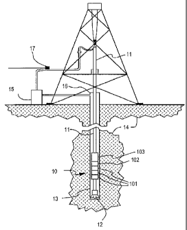
Referring now to the drawings, there is shown in FIG. 1 a
tubular MWD tool 10 connected in a tubular drill string 11
having a rotary drill bit 12 coupled to the end thereof and
arranged for drilling a borehole 13 through earth formations 14.
As the drill string 11 is rotated by the drilling rig,
substantial volumes of drilling fluid ("drilling mud") are
continuously pumped by mud pumps 15 down through the drill
string 11 and discharged from the bit 14 to cool and lubricate
the bit and carry away cuttings removed by the bit. The mud is
returned to the surface along the annular space 16 existing
between the walls of the borehole 13 and the exterior of the
drill string 11. This circulating stream of mud can be used for
the transmission of pressure pulse signal from the MWD tool 10
to the surface.
The MWD tool 10 of this example is an integral part of the -
drill-string bottom hole assembly. It comprises measuring
devices 101 for environmental and drilling parameters and
57.218
_ 7 -
appropriate encoders 102 to reduce and refine electrical signals
representative of the measured parameters for transmission via
mud pulse telemetry signals to the surface. In this example the
MWD tool measures direction and inclination of the hole, gamma
radiation, temperature, and weight and torque on bit. Sensors
and tools for other parameters such as downhole pressure,
downhole resistivity or conductivity of the drilling mud or
formation, neutron spectroscopy etc. might be added. It should
however be obvious that the present invention is not concerned
with any specific kind of parameter or measuring device as used
in the wellbore.
Electrical power for the operation of the tool is provided by
battery producing electrical energy. The tool 10 also includes a
modulator, or mud siren, 103 which selectively interrupts or
obstructs the flow of the drilling mud through the drill string
in order to produce pressure pulses in the mud. Suitable
generators are for example described in US-A-4 785 300, US-A-4
847 815, US-A-4 825 421, US-A-4 839 870 or US-A-5 073 877.
The modulator 103 is controlled such that the pressure pulses
are produced in the form of encoded acoustic data signals which
correspond to the encoded signals from the measuring devices
101. These signals, typically in the form of binary coded
sequences, are transmitted to the surface by way of the mud
flowing in the drill string.
In the present example NRZ (Non-Return-to-Zero) telemetry is
used to communicate information to the surface. In NRZ
modulation the symbols are binary ones and zeros. The system .
states are the modulator closed (corresponding to a one) and the
modulator open (corresponding to a zero). Thus, if two
57.218
g -
succeeding bits are the same the modulator does not move. If a
one follows a zero the modulator closes, if a zero follows a one
the modulator opens.
Other signal modulation techniques are usable, and selection of
the specific encoding and modulation schemes to be employed in
connection with the operation of the modulator are matters of
choice. A number of possible modulation schemes for acoustic
borehole telemetry are described by S.P.Monroe, "Applying
digital data-encoding techniques to mud pulse telemetry",
Proceedings of the 5th SPE Petroleum Computer Conference,
Denver, 25th-28th June 1990, SPE 20236, pp. 7-16.
When these signals reach the surface, they are detected, decoded
and converted into meaningful data by a suitable signal detector
36, which in the present example includes a electro-mechanical
transducer which is generally known in the art as SPT (Stand-
pipe Pressure transducer) 17. Transducers suitable for a
acoustic signal/pressure conversion into electrical signals are
also found in the published UK Patent GB-A-2 140 599, in US-A-5
222 049, or in the published International Patent Application
WO-A-95/14 845.
The analog signal of the SPT is sampled at an appropriate
frequency to derive a digitally coded representation of the
analog signal, which then can be further processed as described
in the following.
Referring now to FIG. 2, the major steps for removing the noise
from transmitted and received signals are described.
57.218 ~ ~ ~_
g _
The first step 21 comprises the identification of noise by
determining its frequency spectrum or at least its major
frequency component or components in a time interval,
hereinafter also referred to as the data vector, which taken
from the received signal.
In a second 22 and third step 23 noise frequencies are selected
and removed from the signal.
After noise removal, an adjacent time interval, i.e., the
subsequent data vector of the received signal is selected (step
24). And the procedure is reiterated until the complete signal
is processed.
It should be noted that the above-described sequence of steps
not necessarily reflects a fixed temporal order. It is for
example feasible to process several intervals of the signals in
parallel and thus accelerating the noise identification.
The noise identification is regarded as one of the key steps of
the present invention; it is described in greater detail making
reference to FIG.3.
The noise identification includes the step 31 of selecting a
data vector. In the current example the data vector spread over
60 to 120 seconds of the received signal. It is centered around
a time reference point.
The following step 32 comprises several processes: As the
signal, and hence the data vector, may be subject to slow trends
or drifts, methods and means for removing these trends are
employed. Preferable this step is performed before any
57.218
~2~152
- 10 -
transformation into the frequency domain. Normally the best-fit
line using least-square based is sufficient to remove a trend
from the data. Other means and methods are readily available to
a person skilled in the art. The parameters for the line fit are
retained for a reconstruction of the data after the noise
removal.
The data vector is then transformed by a Fourier transformation
into the frequency domain. In a particularly preferred variant
of the present example the chosen data vector is multiplied by a
suitable windowing function (such as a flat window with cosine
end-tapers), and padded with zeros - lengthening the data four
or eight fold, thereby enhancing the resolution of the spectrum.
Zero padding introduces side-bands next to the noise peaks, but
these are removed in later step 36 as is described below. The
Fourier transform itself can be performed for example by a
accordingly programmed multi-purpose microprocessor, a digital
signal processor (DSP), or an application specific integrated
circuit (ASIC).
After the spectrum of the data vector is determined in absolute
values, in one variant of the invention, the spectrum is scaled
such that if only signal were present the spectrum would be
approximately flat. For the NRZ telemetry of this example the
spectrum is roughly proportional to the inverse of the
frequency, so the spectrum is multiplied by the frequency to
flatten it. This,step 33 is not essential, but can improve
results.
In a further step 34, a running median filtering process is
applied to the spectrum. The filter has a window length of 0.2
Hz. Essentially this step results in a smoothened version of the
57_218
~~~~~52,
- 11 -
original spectrum, in which all peaks are largely reduced in
height. Though this method generally gives the best results,
other methods, which can be summarized as a weighted median or
mean value based, could be applied to generates a smoothened
version of the spectrum of the signal. Other integrating methods
are feasible.
In another example the (non-windowed) median of the complete
spectrum is used as an approximation of the noise-free spectrum.
In yet a further example, a windowed or shifting mean of the
spectrum is used as an approximation of the noise-free spectrum.
From these different variants, the windowed median filtered
spectrum provides the best results under usual circumstances.
Returning now to Fig. 3, in the next step 35 the smoothened
spectrum is used to identify the peaks in the original spectrum.
This is done by dividing both spectrums and using a threshold to
suppress all amplitude below a threshold, which is S in the
present example. The advantage of using a division rather than
the difference spectrum lies in that the resulting spectrum is
independent from absolute values or units.
To eliminate those side bands which are introduced by the zero-
padding in step 32, from the resulting peak spectrum, any non-
zero intervals in the peak spectrum that are close to, but have
a maximum value smaller than, another non-zero interval are
discarded. Now the frequencies within each interval at which the
peak spectrum attains a maximum are found. If the maximum is
above a second threshold value (usually chosen to be greater
than 6), then this frequency is identified as being narrow-band
57.218
- 12 -
noise frequency. If the maximum is between the two thresholds
then the frequency is only identified as a noise frequency if it
is the same as or very close to a frequency that has previously
been identified as a noise frequency. This is to allow for
frequency drift, and for noise sources whose amplitude goes up
and down.
The results of the above described operations are displayed in
Fig. 4. The frequency scaled spectrum with the prominent noise
frequencies (a,b) is shown in Fig. 4A. A smoothened version of
this spectrum is produced by windowed median filtering (Fig.
4B) .
In Fig. 4C the result of a division of the original spectrum
(Fig. 4A) and its median filtered version (Fig. 4B) is shown.
The resulting "peak spectrum" is dimensionless. The threshold
separates the (assumed) noise (a, b) from the signal.
The result of the process is a (possibly empty) list of
frequencies at which there is narrow-band noise.
The noise removal process make use of the frequency identified
through the previous steps as contaminated with noise. With
these information a variety of different filtering techniques
can be applied to the original data to reduce or cancel the
noise in the signal.
One possibility is to employ notch filters with notches at the
noise frequencies, or adaptive Least-Mean-Square (LMS) methods
described as such by B. Widrow and S.D. Steams in: "Adaptive
Signal Processing", Prentice Hall, 1985, on pp. 212-224 and pp.
99-116, respectively.
57.218 220I5~2
- 13 -
The method used for removing the noise frequencies from the
telemetry signal in the present example includes the step of
generating, for each of the identified noise frequencies, two
noise vectors of mono-chromatic noise at that frequency with a
90 degree phase difference between them, e.g., if the noise
frequency is F then the two noise vectors could be
[1] N1 = sin (27CFt) N2 = cos (2~Ft),
with t from a time interval which is much shorter than the
original interval, in this example 12 seconds as compared to the
60 to 120 seconds length of the noise identification vector.
Synthesizing noise for all the noise frequencies produces a
noise matrix N. Assuming that the data D is corrupted by an
additive noise component according to
[2] D = A N + S,
where D is the vector of data, S is the underlying signal, N is
the matrix of noise synthesized at the narrow-band noise
frequencies, and A is the vector of (unknown) noise amplitudes.
The vector A is found by minimized the residual E, given by
[3] E - ~ I D - A N 12 .
The solution to eq. [3] is given by
57. 228 z2 0l ~ 52
- 14 -
T T -1
[4~ A - (D N ) (N N )
where T denotes the transposed matrix, and the signal is given
by reordering equation [2]:
t5~ S - D - A N .
This process may also be carried out over a slightly longer
noise removal vector, multiplied by a windowing function that is
one over the original range of the removal vector, as defined
above, and beyond goes smoothly to zero, in which case the
noise vectors are multiplied by the same windowing function.
The signal has its trend reinstated, adding back the linear
function removed during noise identification, and a data jump is
avoided by adding a constant to the data such that the last
point of the previously-processed data and the first point of
the current data are the same.
The reference time is then moved forward by the length of the
noise-removal vector, and the process is repeated.
An improvement can be made to the method described above when
the signal is also subject to time-domain spike noise, and the
data has a wider bandwidth than the signal alone. Spike noise
causes problems with Fourier techniques, since when a large
spike is within the noise-identification vector, the frequency
transform is dominated by the spike. Spike removal may be
achieved by using a running-median filter on the data, and
comparing the original data with the median filtered version. An
example of this method is described as such in "Running median
57.218
2~o~~~z
- 15 -
filters and a general despikker", in: Bull. Seism. Soc. Am. 72
(1982), pp. 331-338, by J.R. Evans. If the difference is greater
than a threshold, the original data is replaced by the median
filtered version - if not then it is unaltered. To this end, the
data is low-pass filtered with a bandwidth that exceeds the
signal bandwidth, preferably by a factor of two. The median
filter length is then chosen so that the spikes, after low-pass
filtering will be contained within the filter length. A suitable
length L is given by
F
t6~ L - 3 + 2 * ~
FL
where FN is the Nyquist frequency and FL is the frequency at
which the data has been low-pass filtered.
The process is performed on a general purpose computing machine
which receives the signal from the SPT and on which a suitable
program, e.g. MATLAB~ is installed. Other possibilities for
implementing the method include the use of a dedicated
microprocessor, known as such as DSPs or ASICs.