Note: Descriptions are shown in the official language in which they were submitted.
2201 b~J4
I ~ ALERTNESS AND DROWSINESS DETECTION AND TRACKING SYSTEM
z BACKGROUND OF THE INVENTION
This invention relates to systems for determining a subject's state of
alertness and drowsiness, and more particularly to apparatus and methods for
s analyzing EEG signals acquired from a subject to definitively determine the
subject's state of alertness, drowsiness, or his or her sleep stage, and to
determine
whether the subject's performance is impaired thereby.
THE NEED FOR ALERTNESS MONITORING, DROWSINESS DETECTION,
AND SLEEP STAGING
Io Sleep deprivation has become one of the most significant causes of
11 error and accident throughout our society. The United States Department
I2 of Transportation estimates that 200,000 traffic accidents each year may be
I3 fatigue- or sleep-related. In transportation alone, sleep-related accidents
annually
Ia claim over 5,000 lives, and cause hundreds of thousands of injuries, with
an
Is accumulated cost for health care, death, lost productivity, and damage to
property
16 in the billions of dollars. U.5. Department of Health and Human Services
(1992).
I~ Pilots say their schedules often force them to snooze in the cockpit in
Is order to get enough sleep. Industry insiders report that flight attendants
need to
I9 periodically check to ensure that the crew is awake. The National
Transportation
2o Safety Board (NTSB) cited pilot fatigue as either the cause or a
contributing
zI factor in 69 airplane accidents from 1983 through 1986 Stanford Sleep
Disorders
22 Clinic and Research Center (1991).
2s Recent analyses of spectacular accidents and catastrophes suggest that
1 k3I
2201694
sleepiness may have played an important role in such events, including the
2s . Three Mile Island nuclear disaster and the Exxon Valdez oil spill. Miner
et al.
zs (1988). Such accidents endangered large segments of the population and the
environment.
z8 The presidential Commission on the Space Shuttle Challenger accident
z9 ruled that ground crew fatigue was a contributing cause of the 1986
disaster. In
3o the near catastrophic launch of the shuttle Columbia only three weeks
before,
31 operator fatigue was reported as one of the major factors contributing to
this
3z incident. Stanford Sleep Disorders Clinic and Research Center (1991). Thus
33 the importance of human vigilance or attention is critical to the
performance of
3a individuals in various types of occupations.
35 Each human being requires a specific amount of sleep in each 24-hour
36 period to maintain a functional level of alertness. If an individual
obtains less
3~ sleep, he/she will be less alert the following day. Moreover, sleep loss
accumulates
38 from one night to the next as a "sleep debt." Therefore, only a modest loss
of
39 sleep per night may produce a serious sleep debt when sustained over
several
4o nights. The more sleep lost each day, the greater the sleep debt and the
larger the
41 impairment. Because individuals often do not recognize that they are
sleepy, they
42 seldom guard against involuntary sleep episodes. Much like intoxicated
drivers,
43 sleepy drivers do not realize that they are incapable of adequate
performance, and
44 may therefore deny drowsiness and impairment U.S. Department. of Health and
as Human Services (1992).
46 The effects of sleep loss can be amplified by the bi-modal circadian
rhythm.
2 k31
2201694
Evidence of this can be found in the temporal patterns of accidents attributed
to
48 "falling asleep" or even to mere lapses in operator attention. Studies of
single-
49 vehicle truck accidents in Israel, Texas, and New York all reveal two
distinct peaks
so in the time of day when these accidents occurred. Lavie et al. (1986);
Langlois et
51 al. (1985); G.W. Duff (unpublished observations). One peak occurs in the
early
52 morning hours from 1 a.m. to 7 a.m. and a lower peak occurs during the mid-
53 afternoon from 1 p.m. to 4 p.m.
s4 Another factor which raises risk of accidents is the increasing level of
55 automation. For example, drivers using cruise control and pilots using
automatic
5s flight control systems are more susceptible to drowsiness due to the
removal
of stimulating influences. The Exxon Valdez was on automatic pilot during
sa the critical minutes leading to its grounding as it hit Bligh Reef at 12:04
a.m.
s9 Stanford Sleep Disorders Clinic and Research Center (1991). The NTSB's
so investigation of the accident indicated that the third mate was asleep on
his
feet and failed to respond to the warning light and alarm identifying the reef
62 U.S. Department. of Health and Human Services (1992). Although automation
63 has provided tremendous benefits, it tends to limit operator activity to
vigilant
s4 monitoring of the system. Over a period of time, this can reduce the
awareness
s5 level of the operators and impair their ability to react properly to an
external
66 stimulus. In addition, vigilance is further degraded by sleep loss and
fatigue.
Thus, it would be highly desirable to produce an automated real-time
sa system to track the changes in levels of alertness, such as the transition
from
69 alertness to drowsiness, or the onset of sleep. In addition, there are a
number of
3 k31
2201694
other applications in which an automated system for measuring an individual's
alertness, drowsiness, or stage of sleep would be highly useful. For example,
sleep staging-i.e., the identification of a subject's stage or condition of
sleep
based on physiological indicators-is used clinically for diagnosing and
treating
sleep disorders. Sleep staging is also of interest in medical research.
Normally,
~s sleep staging is performed by a highly trained physician or technician by
studying
voluminous EEG records collected while a subject sleeps. A totally automated
n system for sleep staging could improve consistency and reduce research and
~s treatment costs. Although the sleep scoring field is well established, the
greatest
disagreement among sleep scorers analyzing identical segments of sleep data
80 occurs when scoring the transition from "stage W" (a state of wakefulness)
to
"stage 1" sleep (an initial stage of sleep sometimes referred to as the sleep
onset
82 period).
83 No system is currently available which can effectively use the EEG signal
84 for continuous drowsiness tracking and detection. A recent report to the
United
85 States Department of Transportation (DOT) surveying methods of drowsiness
86 detection acknowledged that automated processing of the EEG signal has
proved
very difficult to implement. Wierwille (1994). Various phases or stages of
sleep
8a are identifiable using automated methods. However, drowsiness and the onset
89 of sleep are much less distinguishable in the EEG waveform, and therefore,
9o much more difficult to identify using automated methods, than are sleep
stages.
91 Research surveyed in the DOT report suggests using a manual method of
92 analyzing EEG and EOG signals. Wierwille (1994), citing Planque (1991).
4 k31
2201694
It should be noted that in many real-world applications, it is insufficient
sa to detect sleep, as normally understood, because it is often essential to
provide
9s a warning before an individual's performance is impaired. In particular,
for
9s critical applications in which a lack of vigilance could affect health and
safety it
is necessary to detect extreme sleepiness. "Extreme sleepiness" is used herein
9s to refer to the state during which sleep is perceived as difficult to
resist, the
9s individual struggles against sleep, performance lapses occur, and sleep
will
10o eventually ensue but has not yet occurred. By detecting the onset of
extreme
101 sleepiness in an individual, the individual may be alerted, or
disqualified from
1o2 service, before they reach a state in which they are incapable of safely
performing
103 a task.
104 PRIOR-ART APPROACHES TO ALERTNESS MONITORING
1os A variety of methods have previously been used or proposed for detecting
1os or evaluating sleep or drowsiness in a subject. Although some prior-art
methods
10~ have been reasonably successful at automated detection of actual sleep,
there
1os has heretofore been no automated system capable of consistently and
definitively
109 detecting the onset of extreme sleepiness before an individual becomes
unable to
11o safely perform a task.
111 ALERTNESS MONITORING USING EXTERNAL MANIFESTATIONS OF
112 DROWSINESS
113 Several prior-art approaches to the automated sleep detection problem have
114 relied on externally observable manifestations of sleep. For example, Chiu
U.S.
ms Patent No. 4,875,030 discloses a system which observes the state of a
subject's
k31
2201694
~1s eyelids while performing a task, such as driving. If the subject's eyelids
remain
closed for a period greater than a normal blink interval, the subject is
determined
118 to be succumbing to sleep, and an alarm is given. This system could be
extended
119 to sound an alarm when some other blink-related characteristic, such as
blink
1zo duty cycle or blink frequency, deviates from established norms. Kishi U.S.
Patent
1z1 No. 5,311,877 discloses a system for estimating a "waking degree" (which
might
122 be a measure of alertness) using an individual's eye blink frequency or
the time
123 required for the individual to react to a visual stimulus. Estrada U.S.
Patent
124 No. 3,953,831, discloses a system which attempts to monitor the attitude
of the
125 subject's head; if the head is observed to droop, then the subject is
determined
1z6 to be succumbing to sleep, and an alarm is given. Slansky U.S. Patent No.
12~ 4,617,559, discloses a fatigue alarm system which employs a pressure-
operated
1z8 switch disposed in a wrapper for a steering wheel or the like; when the
grip of the
1as user becomes relaxed, the switch operates and the alarm is given.
13o These prior-art approaches suffer from a number of important
131 disadvantages, especially in real-time applications involving health or
safety. A
1sz primary disadvantage is that these approaches do not detect drowsiness or
lack
133 of vigilance early enough. If a subject closes his or her eyes, or allows
his or her
13a head to droop, and that behavior is the result of drowsiness, then the
subject
135 may already be at the far end of the drowsiness spectrum, and performance
may
136 already be impaired. In certain applications, eye closure or head drooping
is
137 meaningless in a drowsiness detection system, because such behavior is
neither
1ss necessary nor sufficient for a conclusion of drowsiness or sleep. For
example, there
6 k31
2207694
139 are some environments in which the subject is permitted to rest his or her
eyes for
mo brief intervals, provided that he or she remains awake and vigilant.
Furthermore,
14I detection of eye closure or head drooping produces a binary output, which
has
~4z no further sensitivity once the targeted behavior has been detected. Thus,
in
the aforementioned example, once the subject closes his or her eyes, the
system
~4a cannot distinguish among wakefulness, drowsiness, or sleep.
~4s Another disadvantage of these approaches is that it is relatively
difficult
146 in practice to usefully monitor a subject's physical activity, such as the
state of
147 a subject's eyes or head position. This disadvantage is further compounded
by
~aa the difficulty in using information about physical activity to distinguish
fatigue
149 from transient, but normal, variations in behavior. Estrada, for example,
discloses
~so using a mercury switch to monitor the position of the subject's head. Such
a
I5I switch provides a discrete-valued output, is difficult to adjust, and may
produce
~sz false indications during normal subject and vehicle movement. Although
imaging
153 systems have been proposed for capturing and interpreting an image of the
~sa subject's eye or eyes, such systems require expensive image and signal
processing
rss components. Further, any imaging system must contend with: various eyewear
~s6 and clothing which the subject may employ (e.g., prescription glasses,
sunglasses,
157 contact lenses, hats); large variations in normal lighting conditions;
contamination
158 of the vehicle environment by high-amplitude spurious lighting (e.g.,
illumination
259 by the headlights of another vehicle); and normal movement by the subject.
16o Seko et al. U.S. Patents Nos. 4,564,833 and 4,604,611 disclose drowsiness
16I detection systems for motor vehicles which detect the onset of sleep in a
driver by
k31
2201694
~sz observing a change in the number, rate, or amplitude of certain steering
inputs.
Is3 When a vehicle is being driven along a linear path, the driver typically
makes
Is4 frequent steering corrections by performing a series of small
displacements of
16s the steering wheel in either direction. Because these displacements
typically
166 are small in magnitude and frequently are in the direction opposite that
of the
Is~ previous displacement, they are sometimes referred to as "micro-
reversals." As
168 a driver falls asleep, the resolution of the driver's steering control
degrades. This
Is9 is detectable as a change in the frequency and amplitude of steering
inputs. As
Io a driver becomes sleepy and loses attentiveness, or if the driver falls
asleep for a
171 brief instant and then awakens, the driver will have failed to provide
appropriate
Im steering inputs during that interval. Upon awakening or regaining
attentiveness,
173 the driver attempts to rapidly supply steering inputs which correct the
entire
174 steering error that accumulated during the sleep interval. Thus, changes
in the
ms pattern of steering reversals may indicate that the driver has fallen
asleep or is
Ins about to do so.
1» This method of detecting drowsiness or sleep also has a number of
Ins disadvantages. It is difficult to distinguish between abnormal changes in
steering
179 patterns caused by the onset of sleep and normal steering pattern changes
Iso required by road or traffic conditions which may mimic drowsiness- or
sleep-
181 induced changes. As a result, systems which rely on this method are prone
to false
182 alarms. The method also fails to take into account characteristics of
individual
183 drivers. In addition, because this method relies on measurement of the
subject's
184 actual task performance, it does not detect the onset of sleep until the
subject's
k31
2201694
1as performance is already noticeably impaired. Such detection may not provide
18s sufficient warning to avoid an accident. Furthermore, many tasks which
require
1s~ vigilance do not employ any user inputs under normal conditions; other
tasks
188 require some user inputs, but such inputs may not form recognizable
patterns
1s9 from which abnormal user behavior may be distinguished.
19o ALERTNESS MONITORING USING INTERNAL MANIFESTATIONS OF
191 DROWSINESS
192 Other prior-art automated sleep detection approaches have attempted to
193 measure directly one or more of a subject's internal physiological
characteristics
194 which may indicate alertness or drowsiness. Yoshimi et al. U.5. Patent No.
19s 4,928,090 discloses a system for judging "arousal level" based on a
measurement
19s of skin potential level. A disadvantage of this system is that skin
potential level
197 may be affected by many factors other than arousal or drowsiness, and
therefore
198 it is difficult to distinguish drowsiness-related changes in skin
potential level and
199 changes caused by other factors.
Zoo EEG-BASED APPROACHES
Zo1 The electroencephalogram (EEG) is a recording of the low-voltage
Zo2 electrical activity produced in specific regions of the brain. The EEG
provides
Zo3 a powerful tool for studying both normal and abnormal brain function, and
has
2oa been commonly used to measure and define wakefulness and sleep. There is
Zos considerable evidence that physiological sleepiness is directly related to
the
206 rapidity of the onset of EEG-defined sleep. Torsvall et al. (1987);
Torsvall et al.
(1989); Akerstedt et al. (1990); Akerstedt et al. (1991); Wierwille et. al.
(1992);
k31
2201694
zo8 Dingus et. al. (1987).
209 Sleep is regarded as an active and complex state, and has been
21o characterized in terms of various stages and cycles. The term "sleep
architecture"
211 is used to describe these stages and cycles. The stages and cycles of
sleep may be
212 defined using both external manifestations and internal physiological
processes
213 which can be externally measured, such as EEG and electrooculogram
signals.
214 The electrooculogram (EOG) is a recording of the low-voltage electrical
ns activity associated with eye movement. (t has been observed that the
transition to
21s sleep is also frequently accompanied by slow rolling eye movements (SEMs)
that
21~ can be detected in EOG signals.
21a EEG signals include both periodically recurring or rhythmic features
219 (waves), and transient features, such as "spindles," which do not recur on
a
22o periodic basis and are highly localized in time. One method of summarizing
221 and evaluating the content of EEG records is through analysis of frequency
222 components contained in the EEG signal. Traditional EEG doctrine states
that
223 the information content of an EEG signal is band-limited between roughly
0.5
22a and 30 Hz. Within this range, standardized names have been given to
individual
22s frequency bands. (See Table 1).
k31
2207694
226 TABLE 1: TRADITIONAL EEG SIGNAL FREQUENCY BANDS
22~ Ba nd Lower Upper
22a Name Limit (Hz) Limit (Hz)
229 Delta 0.5 2
23o Theta 3 7
231 Alpha 8 12
232 Beta 13 30
233 A substantial amount of research has been conducted in an attempt to
234 characterize the relationships between a subject's EEG waveforms, the
subject's
2ss state of alertness, drowsiness, or sleep, and the subject's ability to
perform a
23s task. The relationship between performance degradation (slower reaction
rates
?37 and attention lapses) and increased sleepiness has been established by
several
238 researchers. Wilkinson and Houghton (1975); O'Hanlon and Kelley (1977);
239 Dinges (1988); Molodofsky (1992); Trejo and Shensa (1993); Makeig and
Inlow
2ao (1993). Similarly, a strong correlation has been noticed between
performance
241 degradation and particular patterns in the EEG waveform. Horvath et al.
(1976);
242 0'Hanlon and Beatty (1977); 0'Hanlon and Kelley (1977); Makeig and Inlow
24s (1993). In turn, the EEG waveform has also been correlated with vigilance
and
244 sleepiness of subjects in various studies. Gale (1977); Daniel (1967);
Fruhstorfer
2as et al. (1977); Santamaria and Chiappa (1987). Kishi U.S. Patent No.
5,311,877
246 purports to employ "brain waves" and performance measurement in A system
1 ~- k31
2201694
for estimating a "waking degree." Although the meaning of the term "waking
248 degree" is unclear, it is treated as equivalent to reaction time (see Fig.
11), and it
249 might be a measure of alertness. Kishi discloses the use of "brain waves"
analyzed
zso by a "brain wave processor" to supply inputs to the waking degree
estimation
251 unit. However, the particular analysis performed is unclear, and it is
likewise
252 unclear what relationship may exist between a subject's brain waves and
his or her
253 waking degree, or how any such relationship might be exploited.
254 Sleep researchers rely on the EEG in the classification of various phases
or
2ss stages of sleep. However, compared to sleep stages, drowsiness and the
onset
256 of sleep are not as easily distinguishable in the EEG waveform. In
particular,
25~ when drowsiness or sleep onset occur, the changes directly apparent in the
EEG
258 waveform are less profound, and may be masked by events or processes which
259 afFect the EEG but which are not directly related to drowsiness.
26o ALERTNESS MONITORING USING EEG FREQUENCY ANALYSIS
261 One commonly applied method of analyzing EEG signals has been to study
262 the frequency bands in which significant or predominant components of the
263 signals reside. The term "predominant" is used herein to refer to the
frequency
264 bands or components which contain most of the energy in EEG signals. The
26s research to date indicates that drowsiness is associated with a re-
distribution of
266 energy in the traditional frequency bands toward lower frequencies.
However, it
26~ is difficult to use this general guideline in a drowsiness detection
system because
268 of the varied characteristics of EEG signals among subjects. For example,
subject
269 behavior and physiology unrelated to drowsiness can produce changes in the
EEG
12 k31
2201694
o which are similar to those correlated with drowsiness.
Additionally, whether the eyes are open or closed can make a substantial
2n difference in the level of activity in particularfrequency bands of
interest in the
z~3 EEG. Based on sleep stage classification studies, Smith claims that the
EEG can
z~4 be used to identify states of severe sleepiness if the subject's eyes are
open. Smith
ass (1987). In alert subjects with their eyes open, the predominant energy in
the
s EEG signal appears in the beta frequency band (13-30 Hz). A shift of energy
2» into the alpha band (8-12 Hz) occurs as the subjects become drowsy.
0'Hanlon
a and Beatty (1977). For an individual with his or her eyes open, studies
clearly
indicate that increases in alpha and theta activity in the EEG may correlate
with
Zso sleepiness as well as reduced performance. Fruhstorfer et al. (1977);
0'Hanlon
za1 and Kelley (1977); Daniel (1967); Horvath et al. (1976); 0'Hanlon and
Beatty
Za2 (1977). Thus, the appearance of alpha activity in the EEG may be an
indicator of
2s3 drowsiness (an incipient indicator of a loss of vigilance), if the subject
has his or
za4 her eyes open. Santamaria and Chiappa (1987); Makeig and Inlow (1993).
28s If the subject's eyes are closed, however, it is much more difficult to
2ss differentiate between sleepy and alert states. Smith (1987). In
individuals with
zap eyes closed, EEG signal energy is predominantly located in the alpha
frequency
zsa band even though they are wide awake. As sleepiness develops, a subject
whose
Zss eyes are closed generally experiences a reduction in alpha band energy and
an
z9o increase in theta band energy (and possibly delta band energy) present in
the
291 occipital channel of an EEG. Smith observed a pattern of SEMs during
sleepiness
292 with "open eyes" and reported that the studied subjects alternated between
13 k31
2201694
293 open and almost closed eyes. Smith (1987). This may be an explanation for
the
294 increased alpha activity observed during drowsiness. Thus, when the EEG of
an
z9s initially-alert individual with eyes open displays a shift in predominant
energy from
<9s the beta band to the alpha band, that shift might indicate that the
individual has
become drowsy, but it also might simply indicate that the individual has
closed his
zs8 or her eyes but otherwise remains alert. 0'Hanlon and Beatty (1977);
Makeig and
299 Inlow (1993); Santamaria and Chiappa (1987).
30o A number of known techniques seek to characterize the subject's state
301 of alertness or sleep by observing the re-distribution of energy in the
subject's
302 EEG signal among the traditional frequency bands. Some of these
refinements
303 are directed to examining ratios of the energies present in two or more
frequency
304 bands, or examining the ratio of the energy contained in a predefined
frequency
3os band to the total energy in the 0-30 Hz band.
306 Other techniques of EEG signal analysis, which do not principally rely on
the frequency domain, have also been tried. Sleep spindles and K-complexes are
3oa perturbations in the EEG signal which are associated with stage 2 sleep
and are
309 generally recognizable in the time domain. But the presence of sleep
spindles and
K-complexes occurs too late to be useful in detecting drowsiness. Researchers
311 have also tried to use SEMs, which are detectable in EOG signals, as an
indicator
312 of drowsiness. However, none of these have produced a reliable indicator
of
3I3 d rowsi ness.
314 Thus, although it is clear that there exists some information in EEG
signals
315 which indicates drowsiness, and although some prior-art methods have been
k31
221694
316 reasonably successful at automated detection of actual sleep, heretofore
there has
317 been no automated system capable of consistently and definitively
detecting the
318 onset of extreme sleepiness (which functions as a precursor to sleep).
319 INADEQUACIES IN PRIOR-ART METHODS OF ACQUIRING, RECORDING,
32o AND ANALYZING EEG SIGNALS
321 Although the acquisition and recording of EEG signals from human
3z2 subjects has been practiced for many years, conventional acquisition and
analysis
323 techniques have not resulted in strong and consistent correlations between
the
3z4 EEG signal and alertness. Fig. 1 is a simplified block digram of a system
60 typical
325 of those used for recording and analyzing EEG signals for the primary
purpose of
32s medical diagnostics.
At least one signal electrode 64 and at least one reference electrode 66
32s are coupled to a subject 62 from whom it is desired to receive EEG
signals.
329 Although only one signal electrode 64 is shown, it is common in clinical
and
33o research applications to place signal electrodes at several standard
locations
331 on the subject's head to obtain EEG information which correlates with
various
33z physiological and or cognitive processes that occur in different regions
of the
333 brain. The electrodes 64, 66 are typically mechanically secured to the
subject's
334 scalp to provide a relatively low impedance electrical connection
therewith; often,
s3s a conductive gel or paste is used to enhance the conductivity of the
connection.
s3s Although one electrode 66 is designated as the "reference" electrode, such
337 designation is arbitrary because the EEG signal is measured
differentially. The
ssa electrodes 64 and 66 and certain related signal acquisition components (to
be
15 k31
2201694
339 further described) may represent a plurality of duplicate sets of
electrodes and
34o related signal acquisition components.
341 In both clinical and research applications, the traditional means of
3a2 displaying and recording EEG signals has been to supply the amplified
signals to
3a3 a "pen recorder" 74 as shown in Fig. 1. A pen recorder typically has a
strip of
344 paper or chart medium 76 which moves at a predetermined speed in a
longitudinal
34s direction corresponding to the time axis of the chart. One or more pens 88
are
346 mounted to trace one or more continuous lines on the chart as the chart
moves
3a~ longitudinally. A suitable mechanism causes transverse displacement of the
pen
3a$ responsive to a corresponding electrical signal input, so that the pen
traces a
349 record of the amplitude of the signal input over time.
3so With respect to EEG signals, the human body is a relatively high-
3s1 impedance source which produces very low voltage signals (in the microvolt
3sa range) at very low currents. In order to provide sufficient signal
amplitude to drive
353 the pen recorder 74, the EEG signals must be amplified. The electrodes 64,
66
3s4 are connected to an EEG amplifier 70 using suitable leads 68, which are
selected
ass to minimize noise contamination. Leads 68 may be provided with a shield 58
356 as an additional noise reduction step. The EEG amplifier 70 is typically a
high-
357 quality high-input-impedance linear amplifier having a several user-
selectable
358 gain settings in the range of 103-105. A variety of EEG amplifiers are
available
3s9 as commercial products and in various configurations; one EEG amplifier
popular
36o in clinical applications is a component of a commercially available
product sold
361 under the name "Grass Instruments Model 12C Neurodata Acquisition System."
16 k31
2201694
36z Traditional EEG doctrine states that the information content of an EEG
signal is band-limited between roughly 0.5 and 30 Hz. In addition, pen
recorders
3s, necessarily have limited bandwidth because they incorporate electro-
mechanical
365 transducers. Accordingly, conventional EEG acquisition systems include a
suitable
366 filter (shown in simplified form as filter 70 of Fig. 1) as part of the
amplifier
367 electronics. Typically, a first-order Butterworth type filter with a 50 %
amplitude
36a response at approximately 30 Hz is used. Fig. 2 is a graph 88 showing the
1-
369 500 Hz frequency response 90 experimentally derived from a commercial EEG
filter of the first-order Butterworth type, which is available as a component
3m of the aforementioned "Grass Instruments Model 12C Neurodata Acquisition
System." As best seen in Fig. 2, such a filter has a -3 dB point at
approximately
373 21-22 Hz, and a filter roll-ofE of approximately 20 dB per decade. Also,
in many
374 environments, there may be a large amount of electrical noise at the
commercial
s~s power-line frequency (60 or 50 Hz). Substantial contamination of EEG
signals
376 can occur at these frequencies, and therefore, most commercial EEG
equipment
377 provides additional filtering to minimize the efFect of this
contamination.
The analysis of EEGs generally involves the opinions of expert clinicians in
379 conjunction with an off-line data analysis procedure. In order to display
and record
Sao the signal, the amplified and filtered EEG signal 78 is typically supplied
to the pen
3s1 recorder 74. In some applications, it may also be desirable to record or
process
ss2 the EEG signal in electronic form. The amplified and filtered EEG signal
78 may
383 be supplied to an optional post-processing system 80 for storing and
processing
ssa the signal. The post-processing system 80 may employ any of a wide variety
of
17 k31
2201694
38s storage means 82, such as instrument tape recorders and digital storage
systems.
38s Any suitable post-processing functions 84 may be applied to the EEG data
stored
in storage means 82. The results of processing the EEG data may be provided on
a
38s lead or data path 86.
3s9 In some applications, the signal 78 may be converted using conventional
39o techniques into digital form for storage on any suitable digital storage
medium.
391 When a band-limited analog signal is periodically sampled for conversion
into
392 digital form, according to Nyquist's theorem the sampling frequency must
be
39a at least two times the highest frequency in the analog signal.
Accordingly, in
394 applications where EEG signals have been recorded and processed digitally,
395 sampling rates have generally been in the range of 90-275 Hz. EEG
examinations
396 may employ one or several electrodes. Because the examinations are
conducted
397 over periods of five minutes to several hours, a large amount of data must
be
398 collected, stored, and processed. Accordingly, it is highly desirable to
minimize
399 the sampling rate to the extent possible consistent with EEG signal
bandwidth in
400 order to minimize the amount of data storage and post-processing required.
Fig. 3 is a graph 92 showing an excerpt of a sampled EEG waveform 94
402 acquired from a human subject using conventional EEG recording techniques
as
403 generally shown in Fig. 1. This sample.waveform was obtained from the
occipital
404 EEG channel of an awake subject during an alertness test in which the
subject was
405 presented with a time-separated series of visual stimuli and scored on
their ability
406 to promptly respond to each stimulus. This sampled waveform corresponds to
a successful response. This waveform shows the amplitude of the EEG signal in
18 k31
2201694
4os microvolts over a 2-second interval and was acquired at a sampling rate of
256 Hz,
ao9 resulting in 512 data samples.
41o Fig. 4 is a graph 96 showing the power spectral density 98 of the sampled
411 waveform depicted in Fig. 3, over the frequency range 0-128 Hz. The energy
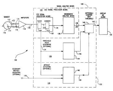
412 within the 0-30 Hz range accounts for more than 99% of the total spectral
energy.
413 Although approximately 1% of the total spectral energy is contained in the
414 frequency range above 30 Hz, it is not visible on the graph of Fig. 4,
which is
41s scaled for viewing the predominant frequency content in the 0-30 Hz range.
41s An interesting feature of graph 96 is the pair of prominent peaks 56 and
417 58 appearing in the power spectrum in the range of 9-11 Hz, which is
within the
41s alpha frequency band. These peaks account for approximately 50.5% of the
total
419 energy in the spectrum. Established EEG doctrine asserts that predominant
42o alpha band energy in the EEG of a subject whose eyes are open is an
indication
421 of extreme drowsiness and is often associated with poor task performance.
422 Surprisingly, although alpha band energy was present (and even
predominant)
423 in this sample, performance was not only acceptable, but corresponds to
one
424 of the fastest reaction times this subject achieved. (The fact that the
subject
425 responded to the visual stimulus, and corresponding data from a
simultaneously
a26 acquired vertical electrooculogram (EOG) signal, verify that the subject's
eyes were open.) This type of contradiction between a subject's alertness, as
42a demonstrated by task performance, and that predicted from the subject's
EEG
429 signals according to traditional doctrine can be seen in other test
samples.
4ao Therefore, an alertness monitoring system that relies heavily on the
presence or
19 k31
2201694
431 shift of the predominant energy in rhythmic EEG signals among the
frequency
432 bands that have traditionally been of interest in EEG research is prone to
error in
433 the form of disagreement between predicted and actual behavior.
434 It is taught throughout the EEG literature and assumed in the design of
43s prior-art alertness monitoring systems that all of the useful information
in the
436 EEG signal is contained in the 0-30 Hz frequency band. For example, Kishi
U.S. Patent No. 5,311,877 purports to employ "brain waves" and performance
438 measurement in a system for estimating a "waking degree." However, Kishi's
439 brain wave processor provides band-pass filters to select only the
traditional EEG
44o frequency bands, and is thus not directed to analysis of EEG signal
components
above 30 Hz.
44z It is believed that all methods, analyses, and systems built on the
443 hypothesis that the useful information in the EEG signal is contained in
the 0-30
444 Hz band share the following characteristics:
44s 1. the analysis focuses on the frequency band of the EEG signal
446 containing the predominant energy;
2. the analysis is directed to rhythmic signal activity at frequencies
448 below approximately 30 Hz (i.e., exclusively in the standard frequency
449 bands according to conventional EEG literature); and
4so 3. the analysis treats as noise, or otherwise discards signal components
4s1 above approximately 30 Hz (e.g., by low-pass filtering).
452 We have observed that higher-frequency components of EEG rhythms,
4ss although not the predominant components, nonetheless contain information
k31
2201694
454 useful for automated monitoring of alertness and drowsiness.
45s Although some research in the EEG field has employed wider filter
4ss bandwidths and higher sampling rates to preserve frequency components in
45~ the EEG signals above 30 Hz, such research has generally been directed to
458 the detection of physiological conditions other than drowsiness or sleep
or has
459 primarily relied on analysis of transient or non-periodic events. There
are several
46o well-known transient events during which higher frequency components
(above
4s~ 30 Hz) are present in the EEG signal. Common sources of high frequency
energy
462 are most often associated with burst activity such as the neurological
"spike"
463 activity observed during an epileptic seizure, and muscle/movement
artifact.
464 Muscle/movement artifact is an extremely common source of high-frequency
4ss contamination found in nearly every EEG record. Sleep spindles are brief
bursts
46s of 12-14 Hz activity in the EEG signal which have been associated with
Stage
467 2 sleep. Sleep spindles are events which are highly localized in time and
are
46s detectable primarily using time-domain analysis. Because they occur only
late
469 in a subject's sleep cycle, they are not generally useful in monitoring
alertness or
4~o drowsiness.
471 Researchers trying to identify spike activity in the EEG (commonly
required
4~z in epileptic research) have increased the bandwidth of their low pass
(anti-
4~3 aliasing) filters and have used faster sampling rates during digitization.
Because
4~4 the high frequency components in spike or burst activity are highly
localized and
475 sharply defined in the time domain, researchers use increased filter
bandwidth
4~6 and sampling rates to capture more of the frequency content of the spike,
thereby
21 k31
2201694
4» improving identification, analysis, and reconstruction in the time domain.
Researchers interested in transient, time-domain events generally have not
employed frequency analysis techniques to study them. For example, Olsen et
al.
4so U.S. Patent No. 5,311,876, discloses a system for automatic seizure
detection
481 using EEG signals, and uses a sampling rate of 200 samples per second.
However,
482 Olsen is directed to detecting seizures, not drowsiness, and attempts to
classify
4a3 events or features in the signals using time-domain analysis techniques,
such as
4s4 counting the number of signal extrema which occur in an analysis epoch.
4ss The transient time-domain events to which the aforementioned EEG
4e6 research has been addressed should not be confused with the continuous
4a~ appearance of high-frequency energy or "rhythms." We are unaware of any
prior
4as art establishing the presence of sustained high frequency rhythms in EEG
signals
489 or relating such rhythms to alertness, drowsiness, or sleep.
The current literature discourages those skilled in the art from exploring
491 the usefulness of high frequency rhythmic activity in EEG signals. For
example,
492 Gaillard refers to frequencies above the beta band as "high frequency
noise".
493 Gaillard (1987), 9-11. Pritchard refers to the higher frequency signals as
white
494 or near-white noise. Pritchard (1995), 378. Carskadon and Rechtswchaffen
state
49s that an upper filter cut-off frequency in the range of 30 to 35 Hz will
generally
496 pass through the "essential" wave forms, while minimizing high frequency
497 interference. Carskadon and Rechtswchaffen (1987), 668. 0'Hanlon and
498 Beatty also refer to "noise" greater than 30 Hz. 0'Hanlon and Beatty
(1977),
499 195. Thus, all of the prior art relating to EEG-based sleep detection has
either
22 k31
2201694
~soo ignored evidence of higher frequency rhythmic activity in the EEG, or has
failed
soy to recognize that such activity may be usefully correlated with alertness
and
sot drowsiness in a practical monitoring or detection system.
sos OBJECTS AND SUMMARY OF THE INVENTION
so4 It is therefore an object of the present invention to provide an automated
sos alertness and drowsiness monitoring system which avoids the disadvantages
of
sob prior-art systems.
soy (t is another object of the invention to provide an automated alertness
and
sos drowsiness monitoring system which reliably provides an indication when a
subject
so9 becomes excessively d rowsy.
s~o It is a further object of the invention to provide an automated alertness
and
sm drowsiness monitoring system which reliably provides an indication of
drowsiness
s~z before a subject becomes incapable of safely performing a task.
sls It is another object of the invention to provide an automated alertness
and
sla drowsiness monitoring system which reliably provides as an output a
continuous
sls measure representing the alertness or drowsiness of a subject.
s~6 It is a further object of the invention to provide an automated alertness
and
sm drowsiness monitoring system which provides an indication of a subject's
alertness
s~s or drowsiness based on information in a subject's EEG signal, including
frequency
s19 components above 30 Hz.
szo It is another object of the invention to provide an automated alertness
and
s2~ drowsiness monitoring system which provides an indication of a subject's
alertness
s22 or drowsiness based on information in a subject's EEG signal, including
non-
23 k31
2207694
sz3 predominant components thereof.
s24 It is a further object of the invention to provide an automated alertness
and
s25 drowsiness monitoring system which provides a reliable indication of a
subject's
s26 alertness or drowsiness from a subject's EEG signal, and which is suitable
for use
5m in real-time applications.
s2s A drowsiness detection system constructed according to the present
529 invention avoids the aforementioned disadvantages of the prior art by
preserving
Sao and analyzing newly discovered rhythmic signal components in selected
frequency
531 bands which the prior art has universally ignored or discarded as "noise."
sae An EEG-based system for monitoring or detecting alertness, drowsiness,
ssa and sleep is provided which exhibits improved performance over prior-art
systems
534 in detecting the onset of drowsiness in a human subject before the subject
actually
s35 succumbs to sleep or suffers a performance failure. The system is referred
to
536 herein as a drowsiness monitoring or drowsiness detection system, although
537 the invention may also find application in alertness monitoring, sleep
staging,
s3a state-of-consciousness monitoring, anesthesia monitoring, and other
related
539 applications. According to the invention, subject drowsiness is strongly
correlated
sao with the energy present in certain rhythmic components of the subject's
EEG
541 signal at frequencies above 30 Hz.
5a2 An EEG-based drowsiness monitoring system constructed according to the
sas present invention includes: acquisition components, signal analysis
components,
544 artifact detection components, and threshold components. The signal
acquisition
s4s components sense the subject's EEG signal, amplify the signal for further
analysis,
24 k3I
2201694
546 and filter certain signal components which apparently do not contain
useful
s4~ information and which degrade further processing and analysis steps. The
signal
548 analysis component receives the amplified and filtered EEG signal,
determines
s49 the amplitudes or energies of the components located in several predefined
s5o frequency ranges, including at least a portion of the frequency range 30-
500 Hz,
551 and determines an output measure signal which represents the drowsiness of
the
ss2 subject. The artifact detection components examine the subject's EEG
signal,
sss and optionally examine secondary indicators of the subject's physical
activity,
ss4 and determine therefrom whether the subject's EEG signal acquired during a
Sss particular time interval is likely to be contaminated by artifact, and
therefore
ss6 should not be used in drowsiness detection. The threshold component
establishes
5s~ a threshold against which the output measure of the signal analysis
component
55a may be compared to determine whether the output measure indicates that the
559 subject is excessively drowsy. The threshold may be determined for the
subject
s6o under examination using EEG signals collected from the subject in a known
state
ss~ of alertness, or may be a universal threshold applicable to the population
as a
562 whole.
s63 (n first and second embodiments of an EEG signal analysis component
5sa constructed according to the invention, primarily digital signal
processing
s65 techniques are used. The analog EEG signal is sensed, amplified, and low-
pass
566 filtered for anti-aliasing. Next, the analog signal is converted to a
digital signal
by an analog to digital converter system. The digital signal may be analyzed
on
56s line in real time, or may be stored for off-line processing and analysis.
During
25 k31
2201694
s69 analysis, a series of small overlapping windows or batches of data
corresponding
o to brief time intervals of the signal are sequentially selected. Frequency
analysis
s» (e.g. a Fast Fourier Transform (FFT)) is used to convert the time-domain
signal
s~z into a frequency domain output vector. Because the EEG signal is non-
stationary,
a windowing function is applied prior to frequency analysis. The power
spectral
spa density (or "power spectrum" ) of the FFT output vector is determined, in
order to
s~s obtain the power in each frequency component. The power spectrum
components
s~s are grouped into a small number of pre-selected spectral bins which
correspond
5n to predefined frequency ranges. The spectral bin components are aggregated
to determine the total energy in each bin, and each of the resulting spectral
bin
s~9 energy values is inverted. Weights are applied to the respective inverted
spectral
sso energy values. An "output measure" signal is determined as the sum of the
ss~ weighted inverted energy values. The output measure is a continuous-valued
582 signal indicating the drowsiness of the subject. The output measure may be
58s compared with the aforementioned threshold to produce a simplified output
signal
584 indicating, for example, that the subject is approaching extreme
drowsiness, or is
sss asleep, or is likely to be incapable of safely performing a task.
586 (n a third embodiment of an EEG signal analysis component constructed
according to the invention, primarily analog signal processing techniques are
used.
588 The signal processing components are broadly analogous to the digital
signal
589 processing components provided in the first and second embodiments.
590 BRIEF DESCRIPTION OF THE DRAWINGS
591 These and other features of this invention will be best understood by
26 k3I
2201694
s92 reference to the following detailed description of a preferred embodiment
of the
593 invention, taken in conjunction with the accompanying drawings, in which:
594 Fig. 1 is a block diagram of an EEG recording system typical of those used
595 according to the prior art;
596 Fig. 2 is a graph showing the frequency response of a low-pass filter used
in
ss~ the prior-art EEG recording system of Fig. 1;
59e Fig. 3 is a graph showing an excerpt of an EEG waveform acquired using an
59s EEG recording system according to prior-art techniques as shown in Fig. 1,
and
60o employing a low-pass filter having the response shown in Fig. 2;
sol Fig. 4 is graph showing the power spectral density calculated over the
602 frequency range 0-128 Hz from the EEG waveform which is depicted in Fig. 3
and
603 which was acquired using the prior-art EEG recording system and low-pass
filter of
604 Figs. 1-2;
605 Fig. 5 is a simplified block diagram showing the general structure of
first
606 and second embodiments of an EEG-based drowsiness monitoring system which
is
constructed according to the present invention and which is adapted for use
with
6os digital signal processing and related techniques;
609 Fig. 6a is a simplified schematic diagram showing a low-pass filter which
61o may be used for anti-aliasing in the inventive EEG-based drowsiness
monitoring
611 system of Fig. 5;
612 Fig. 6b is a graph showing the frequency response of the low-pass filter
of
613 Fig. 6a, for use in the inventive EEG-based alertness monitoring system of
Fig. 5;
614 Fig. 7 is a graph showing an excerpt of an EEG waveform acquired using an
27 k31
2201694
s~s experimental embodiment of the inventive alertness monitoring system of
Fig. 5;
Fig. 8 is a graph showing the power spectral density calculated over the
617 frequency range 0-128 Hz from the EEG waveform which is depicted in Fig. 7
and
6I8 which was acquired using the inventive alertness monitoring system of Fig.
5;
619 Fig. 9 is a graph showing the power spectral density calculated over the
6zo frequency range 31-475 Hz from the EEG waveform which is depicted in Fig.
6z~ 7 and which was acquired using an experimental embodiment of the inventive
sza alertness monitoring system of Fig. 5;
623 Fig. 10 is a graph showing the power spectral density (PSD) calculated
624 by averaging the PSDs over the frequency range 100-475 Hz from 25 EEG data
62s segments collected during experimental trials in which a subject
successfully
626 responded to a presented stimulus;
Fig. 11 is a graph showing the power spectral density (PSD) calculated
6zs by averaging the PSDs over the frequency range 100-475 Hz from 20 EEG data
6z9 segments collected during experimental trials in which a subject failed to
respond
63o to a presented stimulus;
631 Fig. 12a is a block diagram showing the configuration of the subject
632 interface portion of a first embodiment of the inventive drowsiness
monitoring
633 system shown generally in Fig. 5, the embodiment being adapted for
collecting
634 drowsiness-related EEG data in a clinical or research environment;
63s Fig. 12b is a block diagram showing the configuration of the information
63s processing and control portion of a first embodiment of the inventive
drowsiness
637 monitoring system shown generally in Fig. 5, the embodiment being adapted
for
28 k31
2201694
sae collecting drowsiness-related EEG data in a clinical or research
environment;
639 Fig. 13a is a block diagram showing the configuration of the subject
64o interface portion of a second embodiment of the inventive drowsiness
monitoring
system shown generally in Fig. 5, the embodiment being adapted for collecting
6a2 drowsiness-related EEG data in a stand-alone or task-based environment;
sa3 Fig. 13b is a block diagram showing the configuration of the information
644 processing and control portion of a second embodiment of the inventive
645 drowsiness monitoring system shown generally in Fig. 5, the embodiment
being
646 adapted for collecting drowsiness-related EEG data in a stand-alone or
task-based
environment;
64a Fig. 14 is a block diagram of a first embodiment of an EEG signal
processor
649 component which may be used with the inventive drowsiness detection system
650 of Fig. 5, the signal processor component being arranged to use digital
signal
6s1 processing techniques and in conjunction with the clinical or research
environment
s5z of Figs. 12a-126;
653 Fig. 15 is a block diagram of a second embodiment of an EEG signal
654 processor component which may be used with the inventive drowsiness
detection
655 system of Fig. 5, the signal processor component being arranged to use
digital
sss signal processing techniques and in conjunction with the stand-alone or
task-
65~ based environment of Figs. 13a-13b;
658 Fig. 16 is a data-flow diagram depicting, in simplified form, the
processing
65s of EEG signal information acquired from a subject to produce a useful
output
66o measure indicating the drowsiness of the subject, as that information is
operated
29 k31
2201694
661 upon by the processing means of the embodiments of Figs. 5 and 14-15;
ssT Fig. 17 is a block diagram of a third embodiment of an EEG-based
ss3 drowsiness monitoring system which is constructed according to the present
66a invention and which is adapted for use with analog signal processing and
related
s65 techniques;
Fig. 18 is a block diagram of a method for use in conjunction with the
inventive drowsiness detection system of Fig. 5 for detecting artifacts in EEG
sss signal data collected from a subject;
6s9 Fig. 19 is a block diagram of a method for use in conjunction with the
inventive drowsiness detection system of Fig. 5 for determining a drowsiness
671 threshold against which a drowsiness measure of a subject may be compared
to
determine when the subject's performance is likely to be impaired;
673 Fig. 20a is a graph depicting the output measure produced by an
experimental embodiment of the inventive drowsiness monitoring system during
two separate periods of an examination of a human subject. during the first of
676 which the subject was alert and performing a visual test, and during the
second of
677 which the subject was in bed going to sleep; and
Figs. 20b and 20c are graphs depicting the output measure produced by an
experimental embodiment of the inventive drowsiness monitoring system during
6so an examination of a human subject; in which the output measure accurately
6s1 predicted the subject's performance failures.
682 DETAILED DESCRIPTION OF THE PREFERRED EMBODIMENTS
6s3 According to one aspect of the present invention, an EEG-based alertness
30 k31
2201694
684 and drowsiness monitoring and detection system is provided which exhibits
sss improved performance over prior-art systems in detecting the onset of
drowsiness
sss in a human subject before the subject actually succumbs to sleep or
suffers a
performance failure. The inventive system also provides improved performance
sss in a variety of other applications requiring monitoring, detection, or
continuous
689 tracking of a subject's state of alertness, drowsiness, or sleep. The
inventive
sso system also may provide improvements in applications relating to other
aspects of
e91 a subject's alertness, which may not necessarily relate to sleep, such as
monitoring
ss2 aspects of a subject's state of consciousness or response to anesthesia.
Thus,
693 although the system disclosed herein will generally be referred to
henceforth as a
s94 "drowsiness monitoring system" or "drowsiness detection system," the scope
of
695 the present invention shall not be limited by the use of this shorthand
terminology.
696 Broadly defined, an EEG-based drowsiness monitoring system constructed
697 according to the present invention comprises: means for acquiring one or
more
698 EEG signals from a subject; means for filtering the acquired signals to
eliminate
699 signal components which are unimportant or spurious, while retaining
signal
components having a usable correlation with the subject's state of alertness
or
X01 drowsiness; means for processing the signals to select particular
components
which are relevant to alertness and drowsiness and to measure characteristics
of the selected signals; means for eliminating certain signal information
which,
based on analysis of the EEG signals or on external information, appears to be
contaminated by events unrelated to the subject's alertness or drowsiness; and
means for determining an output measure which indicates the subject's
alertness
31 k31
2201694
or drowsiness. Optionally, the system may also comprise means for comparing
the
output measure to a threshold to produce a simplified output signal
indicating,
for example, that the subject is approaching extreme drowsiness, or is asleep,
or
mo is likely to be incapable of safely performing a task.
711 An EEG-based drowsiness monitoring system constructed according to
m2 the present invention may take several different forms. Therefore, this
patent
n3 application discloses three preferred embodiments of the invention, from
which
na an appropriate one may be selected depending on the particular environment
7I5 in which the invention is to be applied and on the cost and availability
of
716 implementing technologies.
~1~ Fig. 5 is a simplified block diagram showing the general structure 100
n$ of a drowsiness detection system constructed according to an aspect of the
n9 present invention. Fig. 5 is a generic drawing which is applicable to all
three
specific embodiments with the understanding that everything outside block
X21 124 is optional and may or may not be present in the specific embodiments.
~z2 Figs. 12a, 12b, 14, and 16 show the structure of a first preferred
embodiment
723 700 of the invention. Figs. 13a, 13b, 15, and 16 show the structure of a
second
na preferred embodiment 800 of the invention. The first and second preferred
~z5 embodiments share many similarities in their methods of acquiring,
processing,
and analyzing EEG information, and may be primarily implemented using digital
signal processing and related technologies. Thus, these two embodiments will
~2s often be discussed together in this application. Fig. 17 is a simplified
block
diagram showing the structure of the third preferred embodiment 400. The third
32 k31
2201694
o preferred embodiment of the invention may be primarily implemented using
analog signal processing and related technologies.
Although these three embodiments may be implemented using different
733 technologies, according to one aspect of this invention, they all share
the features
a of: including particular EEG signal components which have heretofore been
~3s discarded or ignored in accord with the teachings of the prior art; and
exploiting
736 the information contained in these components to provide a reliable
measure
of a subject's alertness or drowsiness. The analog signal processing functions
~3a of the third embodiment are analogous to those performed using digital
signal
739 processing in the first two embodiments. Accordingly, the first and second
embodiments will be discussed first, and the third embodiment will be
discussed
741 subsequently with reference to analogous signal processing functions of
the first
and second embodiments.
743 The first embodiment, which is shown in greater detail in Figs. 12a, 12b,
and 14, may be most appropriate for use in a sleep laboratory, clinical sleep
745 analysis, or other medical or laboratory applications, in which it may be
desirable
746 to acquire large amounts of EEG data for post-processing and/or on-line
analysis
which is not necessarily limited to the recognition of alertness, drowsiness
or sleep.
The second embodiment, which is shown in greater detail in Figs. 13a, 13b, and
15, may be most appropriate in a stand-alone alertness/drowsiness monitoring
and alarm application. For example, the second embodiment might be used as a
~s~ self-contained, real-time device for on-line monitoring of the
alertness/drowsiness
752 of a sonar or radar operator, a nuclear power plant or industrial process
control-
33 k31
2201b94
~s3 room operator, or a vehicle operator.
~s4 In general, the variations between these two embodiments relate to the
ass scale and structure of the data acquisition and processing components.
These
756 variations are the result of differences in the amount of information
which may be
feasibly collected and the uses to which the raw data and analyzed results are
put
in the respective application environments. Fig. 16 is a simplified data-flow-
type
759 diagram showing the transformation of signal information at various
stages, and is
common to both embodiments.
The simplified block diagram of Fig. 5 presents a basic platform for
realizing an EEG-based drowsiness detection system 100 which is constructed
763 in accordance with an aspect of the present invention. The system 100 of
764 Fig. 5 may primarily employ either digital or analog signal processing and
related technologies. Fig. 5 is applicable to all three preferred embodiments.
766 The three embodiments discussed herein differ primarily in their
respective
767 application environments, and in the technology used to implement an EEG
signal
processor component 124. The signal processing components outside block 124,
769 particularly the threshold means and the artifact detection means are
optional
and may or may not be present in the specific embodiments. Further, according
m to another aspect of the invention, a drowsiness analysis component 136
could
»2 be used independently to analyze EEG signals acquired and stored by other
EEG
»s examination systems.
»4 The system 100 comprises suitable means (such as electrodes 112 and
»s 114) for obtaining one or more EEG signals or "channels" 116 from a subject
110,
34 k3I
2201694
amplifier means 118 for receiving and amplifying the EEG signals, signal
analysis
»> means 120 for receiving the amplified EEG signals on lead 130 and producing
an
output signal 142 indicating that the subject is excessively drowsy (or
another
»9 suitable result of the analysis), and means 122 for presenting a display or
alarm
indicating the result of the analysis.
The signal analysis means 120 may be conceptually divided into three main
functional components. EEG signal processor means 124 receives analog EEG
783 signals on lead 130 from amplifier means 118, filters and converts the
signals
~sa into a plurality of digital samples representing the EEG signals, analyzes
the
~8s digital samples, and responsively produces an output measure 138
indicating the
~s6 subject's state of alertness, drowsiness, or sleep. An optional artifact
detection
means 128 receives the digital samples from EEG signal processor means 124,
ass and analyzes the samples, and possibly other information, to determine
whether
the samples are apparently contaminated by artifacts, and therefore cannot be
o reliably used. An optional threshold means 126 generates a suitable
threshold
791 value (on lead 146) which is compared with the output measure 138 produced
by the EEG signal processor means 124. The result of the comparison may be
793 a simplified output signal 142 indicating that the subject has reached or
passed
a threshold stage of drowsiness or sleep. The threshold means 126 may use as
~9s threshold value 146 a universal value believed to be generally applicable
to the
796 human population, or may optionally determine the threshold value 146 for
an
individual using baseline EEG signals acquired therefrom.
~9a The conceptual division of signal processing and analysis means 120 into
2201694
799 several functional components is useful in describing its operation, but
when
goo implemented, signal analysis means 120 need not have separate
corresponding
gol physical components. For example, depending on application requirements,
all
sot of the functions of signal analysis means 120 could be implemented using
one
8o3 or more high-performance computer-based systems, or a single-board signal
8o4 processing system, or even a single-chip digital signal processor.
gos EEG signals may be obtained from a human subject 110 using any
806 appropriate means, of which several methods are well known in the art. The
most
807 commonly used method of obtaining EEG signals is to apply suitable
electrodes,
gob such as electrodes 112 and 114 (Fig. 5), at various locations on the
subject's
809 scalp in order to detect particular rhythmic EEG signals known to carry
desired
glo information.
811 The "International 10-20 System" of electrode placement has become the
812 standard instrument in research and clinical neurophysiology. The 10-20
System
813 determines electrode locations based on the size of the subject's head and
is
81a therefore specific to individuals. Use of the 10-20 System of electrode
placement
81s assures accurate and repeatable placement of electrodes for an individual
across
816 multiple occasions and examination facilities, and allows the comparison
of
817 EEG signals between subjects. The detailed head measurements and electrode
818 application techniques will not be described here, but are disclosed in
many
819 handbooks on EEG technology. Some commonly used location names are:
frontal
8zo (F), central (C), parietal (P), occipital (0), and anterior (A). (t is
believed that
821 among the standardized scalp locations, the location pairs 02-A1 and O1-A2
are
36 k31
22Q1694
822 good for use in detecting drowsiness.
823 Typical EEG electrode connections in clinical applications may have an
824 impedance in the range of 5-10 K ohms. It is generally desirable to
minimize
82s the impedance of the connections between the electrode and the subject.
82s Laboratory-grade electrodes may be used to form connections with
impedances
82~ below 2 K ohms. A conductive paste or gel may be applied to the electrode
to
828 further improve the conductivity and mechanical stability of the
connection.
829 Commercially available "active electrodes," which provide an amplifier on
or near
83o the electrode, may also be used. Needle electrodes may be applied
subcutaneously
831 in laboratory applications.
832 (n some other applications, the mechanical configuration or stability
833 of the electrodes, or the ease of applying the electrodes to the subject,
or the
834 compatibility of the electrodes with the subject's mobility, are high
priorities.
83s Capacitively coupled electrodes may also be used. Additionally, a
lightweight EEG
836 sensor could be advantageously provided in a suitable headset (not shown)
having
a sufficient number of electrodes.
838 Because the electrical currents of the EEG signals produce associated
839 magnetic fields, methods have been proposed for sensing these magnetic
fields to
84o acquire signals equivalent to conventional EEG measurements without
electrical
84~ contact with the subject. Such signals are referred to as
magnetoencephalogram
sae (MEG) signals. One of ordinary skill in the art will appreciate that the
present
s43 invention could be used with MEG signals with little or no modification.
8a4 To maximize clarity, the block diagram of Fig. 5 depicts collection and
37 k31
2201694
sas processing of a single EEG channel. However, one skilled in the art will
appreciate
Bas that an inventive drowsiness detection system could advantageously collect
and
process multiple EEG channels. If desired, collection and processing of
multiple
aa8 EEG channels may be accomplished by simply replicating all of the
components
sag shown on a per-channel basis. Alternatively, one could use multiplexing,
computer
sso multi-tasking, and other techniques which are known in the art for
processing
8s1 multiple signals with a smaller number of processing means and signal
paths.
8sz The number of EEG signals to be processed depends on the environment
8s3 in which the drowsiness monitoring system is to be used. In laboratory or
8s4 clinical environments, it may be desirable and relatively convenient to
collect
ass and process EEG signals obtained at several locations on the subject's
scalp.
8ss Skilled technicians are available to apply the electrodes, and portability
of the
asp signal acquisition and analysis equipment is not a high priority. In stand-
alone
858 environments, where a subject is to be monitored while performing a real-
world
8s9 task, technicians may not be available to apply the electrodes, and
subject
86o mobility requirements may limit the size and weight of the signal
acquisition
861 and analysis equipment. In such environments, it may be feasible to
collect
862 and process only a few channels, or only a single channel, of EEG data.
When
863 processed and analyzed according to the present invention, a single
channel of
8r~ EEG data is sufficient to reliably track or detect the onset of extreme
drowsiness
86s in a human subject.
866 The number of electrodes required depends on the number of EEG
86~ signals to be processed. At least two electrodes (one signal electrode,
such as
k31
2201694
sss electrode 112 (Fig. 5), and one reference electrode, such as electrode
114) are
8s9 required to obtain one EEG channel. The number of electrodes needed to
obtain
o greater numbers of EEG signal channels depends on whether separate reference
e» electrodes or a single reference electrode is used.
As noted previously, the EEG signals as measured are very low voltage
ass signals (in the microvolt range). In order to provide sufficient voltage
levels for
s~4 further processing, the EEG signals must be amplified. Any suitable cables
or
8~s wires 116 may be used to connect the electrodes 112 and 114 to an
appropriate
EEG amplifier means 118. Care should be taken to minimize interference from
8m electrical noise sources. For example, cable 116 may include a shield
conductor
174.
EEG amplifier means 118 may be implemented using a suitable high-quality
eeo amplifier having a high input impedance and sufficient gain to amplify the
EEG
say signals for input to the signal analysis means 120. As will be discussed
further,
8a2 the signal analysis means 120 is nominally configured to receive an output
signal
on lead 130 in the X2.5 volt range from amplifier means 118. However, another
s84 appropriate voltage range could be selected for the amplified signal,
provided
s$s that both the output of amplifier means 118 and the input of the signal
analysis
ash means 120 are compatible. High linearity, low distortion, flat frequency
response,
asp and good common-mode rejection are desirable characteristics for amplifier
Bas means 118. EEG signal levels available at the input of amplifier means 118
may
vary, depending on the subject, the type of electrode (or other probe device)
ego used, and the quality of the connections obtained. Preferably, amplifier
means
39 k31
220ib94
118 provides several operator-selectable gain settings to accommodate such
s92 variations. Because the amplifier means 118 will be electrically connected
to a
893 person, amplifier means 118 must be designed and constructed consistent
with
894 applicable safety standards for such equipment.
s9s Several commercially available amplifiers, which have been specifically
s96 developed for use in collecting EEG signals and meet these requirements,
could be
a9~ used. One such amplifier popular in clinical EEG applications is a
component of a
898 commercially available product sold under the name "Grass Instruments
Model
899 12C Neurodata Acquisition System." In stand-alone applications where low
90o cost and subject mobility are high priorities, commercially available
operational
amplifiers ( "op-amps" ) in single-chip or module form might be used in this
9oz application. One skilled in the art would appreciate how to select a
suitable op-
903 amp (and support components), or other suitable means, such as a portable
EEG
904 system, for use in this application.
905 As best seen in Fig. 5, an amplified EEG signal is provided on lead 130 to
906 an EEG signal processor means 124 which is a component of the signal
analysis
means 120. The signal on lead 130 is an "analog" signal. The first and second
9os preferred embodiments of this invention, are preferably implemented using
digital
909 signal processing and related technologies. Accordingly, in those
embodiments,
the analog EEG signal must first be digitized-that is, converted into a series
of
911 digital samples which represent the original EEG signal with sufficient
accuracy.
EEG signal processor means 124 comprises an EEG signal acquisition means
913 132 (including a filter 164 and an analog-to-digital (A/D) converter 212)
and
4~ k31
2201694
r
91a a drowsiness analysisineans 136. The filter 164 filters the EEG signal,
and the
91s converter 212 sampled and converts the EEG signal into digital form, and
may
s
916 store the converted samples. The drowsiness analysis means 136 analyzes
the
917 samples and produces therefrom an output signal on lead 138 which serves
as a
91s "measure" of a subject's state of alertness, drowsiness, or sleep.
919 Prior-art attempts at automated drowsiness detection using EEG signals
9zo have systematically discarded or ignored EEG signal components at
frequencies
921 greater than approximately 30 Hz, a factor which we believe has been a
significant
contributor to the failure of such systems. According to one aspect of the
923 present invention, reliable and accurate information concerning a
subject's
9za state of alertness, droirvsiness, or sleep is extracted from EEG signal
components
9zs in frequency ranges well above those considered relevant by traditional
EEG
926 doctrine. Prior-art EEG recording systems have filtered out these
frequencies
as "noise." According to this invention, these frequencies are preserved and
9zs analyzed.
929 We have determined experimentally that particularly useful information
93o resides in the frequency range of approximately 80-475 Hz. Accordingly,
the
931 frequency range of 80-475 Hz is discussed herein merely as an example of
932 frequencies above 30 Hz which are of interest in the analysis of EEG
signals
933 for information concerning a subject's state of alertness, drowsiness, or
sleep.
934 Drowsiness detection systems which use this exemplary frequency range may
935 be constructed consistent with the preferred embodiments of the invention
disclosed herein, and v~ould provide significantly improved performance over
prior-
41 k31
2201 X94
art systems. However, it is believed that at feast some of the advantages of
the
938 present invention may be obtained using any reasonably selected subranges
of
939 frequencies between approximately 30 Hz and 500 Hz. In addition,
frequencies
94o above 30 Hz which are outside the exemplary frequency range of 80-475 Hz
may
941 also be found useful upon further study, and if used might enable
drowsiness
94z detection systems to provide satisfactory or improved performance.
Therefore,
943 embodiments of the invention may be designed to acquire and analyze an
944 expanded range of frequencies, even above 475 Hz.
94s In order to analyze such high frequency information, the EEG signal must
946 be sampled at a sufficiently high rate during digitization, and a properly
designed
947 anti-aliasing filter must be used to condition the signal prior to
sampling. (t
948 is known that a band-limited signal can be uniquely represented by a
plurality
949 of regularly spaced samples if the rate f5 at which samples are taken is
at least
9so twice the highest frequency fmaX in the original sample. For example, in
order
to sample a signal containing components at frequencies up to an exemplary
9s2 maximum frequency fmax of 475 Hz, the minimum sampling rate f5 would be
9ss 950 samples per second (5P5), but any sampling rate greater than 950 SPS
954 could be used. In a prototype embodiment of the invention, a sampling rate
fs
9ss of 950 Hz was used to collect data (discussed below in detail) concerning
the
9s6 performance of the invention in detecting drowsiness. Although the
sampling rate
9s~ may be increased to the limits of available technology, faster sampling
increases
9s8 the cost of equipment and the amount of signal data which must be
processed.
9s9 Inexpensive commercially available equipment could be advantageously
employed
42 k3I
2201694
o in preferred embodiments of the invention to allow exploitation of EEG
signal
961 information at higher frequencies.
Drowsiness monitoring system 100 preferably comprises suitable anti-
9s3 aliasing low-pass filter means 164 for attenuating signal components above
9s4 the maximum frequencies desired for drowsiness detection, thereby
providing
9s5 a band-limited signal for digitization. Filter means 164 is shown in Fig.
5 as an
96s integral part of EEG signal acquisition means 132, but it may be located
elsewhere
provided that it operates on the EEG signal before sampling, and could be, for
9se example, integrated with the EEG signal amplifier 118. It is conventional
to
969 employ a low pass filter 70 (Fig. 1) in an EEG recording system, and a
variety of
o such filters are commercially available. However, the commercially available
filters
9» designed for conventional EEG recording applications are not preferred for
anti-
aliasing because they employ a low-order design (such as first-order
Butterworth)
973 resulting in a shallow filter roll-off (see Fig. 2).
If the previously mentioned exemplary frequency band of 80-475 Hz were
975 selected for use with the first and second preferred embodiments discussed
herein,
a minimum sampling rate f5 of 950 Hz could be used. A low-pass (anti-aliasing)
9» filter providing 50 dB of attenuation in the stop band would be sufficient.
A sixth
order Butterworth filter having a -3 dB point selected at 182.1 Hz provides at
least
979 50 dB of attenuation at 475 Hz and above and can be affordably implemented
9so with commercially available components. This type of filter has a more
rapid
transition from the pass band to the stop band than the shallower first-order
9s2 response of filters typically implemented in EEG equipment.
43 k3I
220i~94
983 Fig. 6a is a schematic diagram of a low-pass anti-aliasing filter means
164a
9s< which has these characteristics and which is suitable for use in
conjunction with
98s the drowsiness monitoring system 100 (Figs. 5, 14, 15) of the present
invention.
9se Fig. 6b is a graph 644 showing the frequency response 646 of the low-pass
filter of
9a~ Fig. 6a. As best seen in Fig. 6b, the attenuation of the filter 164a
begins within
98s the frequency band of interest. However, subsequent processing may be used
to
989 compensate for this attenuation (see filter compensation means 230, Figs.
14 and
990 15), or a higher sampling rate could be used to allow the filter's -3 dB
point to be
991 moved beyond 182.1 Hz, thereby extending the pass band of the filter.
992 As best seen in Fig. 6a, anti-aliasing filter means 164a comprises a
suitable
993 power supply 612 (which may be shared with other signal acquisition
equipment),
994 an optional input bufFer amplifier 614, an optional output buffer
amplifier 620,
99s a filter module or circuit 616, and an oscillator module 618 for
determining
996 the cut-off frequency of the filter module 616. Power supply 612 may be
any
997 suitable regulated DC power supply providing at least a first output "V-"
626
99a at approximately-5 volts, and a second output "V-f-" 628 at approximately -
f-5
999 volts, referenced to a common ground 654. Power supply 612 is preferably
of the
log "linear" type which generally provides reduced noise at the power supply
outputs
(compared to "switching" power supplies).
A suitable power supply 612 is commercially available from Power-One,
Inc., 740 Colte Plano, Camarillo, California 93012, under the designation
"International Series, Model HCCS-6/OVP-A," but other power supplies could
coos also be used. The power supply outputs 626, 628, and ground reference 654
44 k31
2201594
loos may be supplied to other data acquisition components, such as analog-to-
loo~ digital conversion means 212 (see Figs. 14 and 15) to allow the analog-to-
digital
loos conversion means 212 access to a low-noise source of power without
providing
I009 an additional power supply. The power supply 612 may receive power from
any
logo suitable source, such as leads 622 and 624 connected to a domestic AC
power
IOII source. In a vehicular application, a suitable DC-DC power supply could
be used,
1012 and leads 622 and 624 could be connected to the vehicle electrical
system. In an
1013 application where portability is desired, power supply 612 could be
replaced with a
1014 suitable battery.
loll Any suitable high-performance low-pass filter circuit 616 providing
loll sufficient attenuation could be used to implement the filtering function
of
l01 filter means 164a. In a preferred embodiment of the invention, a sixth-
order
1018 Butterworth-type switched capacitor low-pass filter may be used as the
filter
1019 circuit 616. Such a filter is commercially available, packaged in a
single integrated
lozo circuit (IC), from National Semiconductor Corporation, Santa Clara, CA
under
lozl the designation "LMF60CIN-100." However, other filter circuits could also
be
1022 used.
1023 The LMF60 switched capacitor filter circuit advantageously provides a
1024 high-performance filter and requires few external components. The filter
circuit
lots 616 uses an externally derived clock signal supplied on lead 634 to
determine its
1026 cut-off frequency. The cut-ofF frequency is obtained by dividing the
clock signal by
102 100. The LMF60's sixth-order Butterworth design provides a minimum stop-
band
lots attenuation rate of approximately 36 dB per octave. In an embodiment
which
4 ~J k31
2201694
~oz9 employs a sampling rate fs of 950 Hz, the resulting sampling system upper
limit
o frequency f5/2 is 475 Hz. A cut-off frequency of 200 Hz is suitable for use
with
1031 this filter to provide at least 50 dB attenuation at 475 Hz. Accordingly,
a 20 KHz
1032 filter clock signal may be provided on lead 634 to select a 200 Hz cut-
off. One of
1033 skill in the art will appreciate that filters having different cut-off
frequencies and
I034 stop-band attenuation rates could also be used as desired provided that
sufficient
I035 attenuation is provided at the sampling system upper limit frequency
f5/2.
1036 Filter means 164a comprises an appropriate oscillator circuit 618 which
provides the clock signal for filter circuit 616. Any suitable 20 KHz
oscillator
1038 could be used. In a preferred embodiment of the invention, a crystal-
controlled
1039 oscillator having an integrated externally-programmable divider chain may
be
1040 used to provide the 20 KHz clock signal. An integrated crystal oscillator
and
divider circuit 618 which may be used in the filter means 164 of the present
1042 invention is commercially available from Epson America, Inc. under the
X043 designation "SPG-8651B." As best seen in Fig. 6a, oscillator 618 has a
plurality
1044 of control inputs 632 by which operation of the internal divider chain
may be
1045 programmed. In order to produce an output of 20 KHz with the SPG-8651B
1046 integrated circuit, control inputs C1 and C3 must be connected to V-f-
via lead
1047 628, and control inputs C2 and C4-C6 must be connected to ground via lead
a 654. The output signal from oscillator 618 is supplied to filter 616 on lead
634.
1049 The use of a programmable divider advantageously allows a variety of
different
loco clock frequencies to be selected as desired for a particular application.
Other
I051 suitable oscillator/divider circuits which can produce different
selections of output
46 k31
2201694
1052 frequencies are commercially available.
1053 With reference once again to Fig. 5, the EEG signal from EEG amplifier
118
1054 is provided to filter means 164 on lead 130. The anti-aliased EEG output
signal
1055 from anti-alias filter means 164, is supplied to signal sampling and
conversion
1056 means 212 (Figs. 5, 14, 15) on lead 310. As best seen in Fig. 6a, the EEG
signal
105 is preferably buffered by an input buffer amplifier 614. Lead 130 is
connected to
lose the input of the input buffer amplifier 614. The output of the buffer
amplifier 614
1059 is connected to the input of the filter means via lead 630. The input
impedance
1060 of the filter circuit 616 may be undesirably low. The input buffer
amplifier 614
1061 may be used to present a higher input impedance to the EEG signal
supplied on
1062 lead 130. Any suitable amplifier could be used for input buffer amplifier
614. The
1063 LMF60 filter IC includes two uncommitted operational amplifiers, of which
one
1064 could be used as a buffer amplifier 614. However, another commercially
available
1065 operational amplifier could also be used. Alternately, lead 130 may be
connected
I066 directly to the input of filter circuit 616.
1067 An output buffer amplifier 620 is preferably provided to isolate the
filter
1068 circuit 616 from the filter means output lead 310. The filter circuit
output lead
1069 636 is connected to the input of the output buffer amplifier 620; and the
output
logo of amplifier 620 is connected to the filter means output lead 310. Any
suitable
1071 amplifier could be used for output buffer amplifier 620. The LMF60 filter
IC
lo~z includes two uncommitted operational amplifiers, of which one could be
used
1073 as an output buffer amplifier 620. However, another commercially
available
1074 operational amplifier could also be used. Alternately, filter means
output lead 310
47 k31
zzon~4
logs may be connected directly to the output of the filter circuit 616.
1076 The anti-aliased EEG signal output from filter means 164 is provided to
1o» signal sampling and conversion means 212 (Figs. 5, 14, and 15) on lead
310.
logs Signal sampling and conversion means 212 may be implemented using any
1079 suitable analog-to-digital converter system capable of sampling at the
desired rate
loco and providing sufficient resolution (or precision). Analog-to-digital
conversion at
loll a resolution of 12 bits (i.e. 4096 discrete values) is adequate, but
conversion at
lose higher resolution (such as 16 bits) may result in greater overall
performance of the
1083 drowsiness detection system.
1084 In clinical or laboratory applications, such as the environment in which
the
loss first preferred embodiment 700 (see Figs. 12a, 12b) of the invention may
be used,
loa6 a general purpose computer system may be employed as an acuisition
control and
loss processing means 216a (Fig. 12b) for EEG data collection. The computer
system
loss is preferably equipped with an interface card or accessory containing one
or more
1089 analog-to-digital converters and suitable control software to drive the
converters
1090 and save the converted samples. The EEG signal is converted into digital
samples
1091 for subsequent analysis using digital signal processing techniques. For
example,
Io92 many small "personal computers" may be used.
1093 A suitable analog-to-digital interface card for use in a general-purpose
logs computer is commercially available from Keithley MetraByte, Inc., 440
Myles
1095 Standish Boulevard, Taunton, MA, 02780, under the designation "DAS-
1096 1802HR." As noted above, when processed and analyzed according to the
present
loss invention, a single channel of EEG data is sufficient to reliably detect
the onset
48 k31
2201594
I098 of extreme drowsiness in a human subject. In addition, a sampling rate of
950
Io99 samples per second appears to be adequate to acquire an exemplary range
of
Iloo frequencies of interest in drowsiness detection. However, it may be
advantageous
1101 to collect EEG signal data obtained from a plurality of electrode
locations, or
mot to collect data at higher rates. The aforementioned interface card is
capable of
1103 sampling and converting up to 8 fully differential analog channels to
digital data
1104 at a resolution of 16 bits at an aggregate rate of 100,000 samples per
second. If all
Ilos eight channels are used, the interface card can accommodate a sampling
rate of
Ilos approximately 12,500 samples per second, which allows signals up to 6,250
Hz to
IIO~ be sampled. Other analog-to-digital interface cards could also be used.
Ilos In a stand-alone application, such as the environment in which the second
1109 preferred embodiment 800 (see Figs. 13a, 13b) of the invention may be
used,
1110 it may be a priority to implement a drowsiness detection system 840 in an
1111 inexpensive and highly portable package. Signal sampling and conversion
means
1112 212 may be implemented using a small general-purpose computer, which may
be
I113 equipped with an analog-to-digital interface card as described above.
1114 As an alternative, signal sampling and conversion means 212 could be
IIIS implemented using any appropriate single-board computer which is equipped
1116 for signal processing applications, of which several are commercially
available.
1117 For example, Texas Instruments produces several board-level products for
II18 digital signal processing applications which may be used. A suitable
single-
1119 board computer for use in this application would provide: at least one
channel of
1120 analog-to-digital conversion capable of a sampling rate of at least 950
samples
49 k3I
2201694
1121 per second; a digital signal processor or other high-performance
microprocessor
1122 to control data acquisition; sufficient memory for storing control
software and
1123 acquired data; and means for presenting the acquired data for analysis.
1124 Another alternative would be to implement signal sampling and conversion
112s means 212 using a single-chip microcomputer having suitable on-chip
facilities
1126 for analog-to-digital conversion. For example, a single-chip
microcomputer
~~2~ commercially available from Motorola, Inc., Austin, TX 85284, under the
1128 designation "MC68HC11A8" includes an analog-to-digital converter which
can
1129 sample and convert up to four analog signal inputs at approximately
15,000
1130 samples per second, producing 8-bit results. Although higher resolution A-
D
11x1 conversion results would be desirable, 8 bits of A-D resolution may be
adequate
1132 for some drowsiness detection applications.
1133 Once EEG signal data is acquired and converted by the signal sampling and
1134 conversion means 212 (Figs. 5, 14, 15), the data is provided to the
drowsiness
1135 analysis means 136 (Figs. 5, 14, 15~, which analyzes the data and
produces
1136 therefrom an output signal on lead 138 which serves as a "measure" of a
subject's
1137 state of alertness, drowsiness, or sleep. The operation of the drowsiness
analysis
113s means is described in greater detail in connection with Figs. 14-16. Any
suitable
1139 general-purpose computer, or a special-purpose digital signal processing
system,
1140 may be used to implement the drowsiness analysis means 136. A general
purpose
1141 computer may be used to control EEG signal acquisition means 132 and to
1142 perform all of the other processing functions of signal analysis means
120,
1143 including those of the drowsiness analysis means 136, threshold means
126, and
50 k31
2201694
1144 artifact detection means 128.
~~as (f a general-purpose computer is used, capabilities required of the
computer
1146 will depend on the sampling rate, the number of EEG signal channels to be
may analyzed, and whether the results of the analysis are required in an on-
line mode.
m4s In some applications, such as in clinical diagnostics, it may be
appropriate to
1149 collect a large batch of EEG data for subsequent analysis. In other
applications,
1150 and particularly in stand-alone environments in which a drowsiness
detection
1151 system is used to provide a warning when a subject performing a task
becomes
ms? unable to perform the task safely, it is essential to analyze the data and
produce a
ms3 real-time result. For a single EEG signal sampled at approximately 1000
samples
1154 per second, a medium performance personal computer having an Intel "i486"
1155 or equivalent central processor is suitable for implementing the
functions of the
1156 drowsiness analysis means 136 in real time; lower performance computers,
such
IZ57 as a single-chip microcomputer, may also be usable. For a plurality of
EEG signals
mss sampled at higher rates (e.g., 4 signals sampled at 12,000 samples per
second), a
II59 mid-range workstation or high-performance personal computer may be
suitable,
1160 such as personal computer models having Intel Pentium brand processors.
1161 As best seen in Fig. 5, the signal analysis means 120 preferably also
1162 comprises a threshold means 126 responsive to the value of an output
measure
1163 138 produced by the EEG signal processor means 124 to produce an output
signal
1164 142. This output signal 142 would indicate the level of alertness,
drowsiness, or
1165 sleep of the subject relative to the threshold. As best seen in Figs.
20a, 20b, and
1166 20c (discussed further in greater detail), the output measure 138 is
preferably a
1 k31
2201694
1167 continuous quantity representing the instantaneous drowsiness of the
subject.
11s8 An exemplary method of determining the output measure is discussed
further in
1169 greater detail in connection with Figs. 14-16, but it may be briefly
characterized
Ilo as a weighted sum of the inverse of the energy of a subject's EEG signal
in
lln selected frequency bands.
1172 We have determined experimentally that for any particular subject, the
II73 output measure 138 is useful as a relative indicator of drowsiness. The
measure
ll~a increases in magnitude in response to the increased drowsiness of the
subject.
1m5 According to one aspect of the present invention, EEG data may be
collected
1176 from an alert individual and used to establish a threshold such that
values of
1177 the measure which exceed the threshold reliably indicate excessive
drowsiness
Im8 in that individual. As best seen in Fig. 5, threshold value generator
means 144
1179 preferably receives on lead or data path 134 certain baseline EEG data
which
118o was collected by EEG signal acquisition means 132, and provides a
drowsiness
118I output measure threshold value or signal on lead 146. A process 510 for
use in
1182 connection with threshold value generator means 144 for determining a
subject's
1183 drowsiness threshold from baseline EEG data acquired from the subject is
shown
1184 in Fig. 19, and is discussed further in greater detail. However, it may
not always
Ilea be desirable or convenient to obtain baseline EEG data from the subject.
It
1186 is believed that a predetermined universal threshold value, which has
been
1187 determined experimentally, may be used with most of the population to
provide
Ilea acceptable drowsiness detection results.
1189 Threshold means 126 preferably includes comparison means 140 for
~J 2 k31
2201694
1190 comparing the output measure 138 produced by the EEG signal processor
means
1191 124 with the threshold value on lead 146 to produce a simplified output
signal
1192 on lead 142 indicating that the subject has reached or passed a threshold
of
1I93 drowsiness or sleep. Comparison means 140 preferably also receives a
signal
1194 on lead 150 from artifact detection means 128 indicating that the EEG
signal
1195 currently being analyzed appears to be contaminated by artifact and one
may
11~ choose not to use this data in determining the subject's drowsiness.
11s~ Any appropriate comparison device or process could be used to implement
II98 comparison means 140, depending on the form of the signals or data to be
II99 compared and on the desired form of the output. In an embodiment which
lzoo employs digital signal processing, the values of the output measure, the
1201 threshold value, and the artifact detection signal may be stored in
locations
lzoz which are updated from time to time. (n that case, the comparison means
140
lzos may be implemented using a software comparison routine. However, in other
1204 implementations, the output measure, the threshold signal, and the
artifact
1205 detection signal, could appear as individual digital signals, or as three
separate
1206 analog signals, and any suitable comparator hardware, such as magnitude
lzo~ comparators or analog comparators, could be used to implement comparison
lzos means 140. The output signal on lead 142 may be used to drive an
appropriate
1209 display or alarm 122 device to indicate that the subject being monitored
by the
121o drowsiness detector is excessively drowsy.
121I As best seen in Fig. 5, the signal analysis means 120 preferably
comprises
122? artifact detection means 128 for determining whether the EEG samples
acquired
53 k3I
2201694
1213 from the subject are apparently contaminated by artifact. Artifact
detection
1214 means 128 preferably provides an output signal on lead 150 to comparison
means
1215 140. In this case, comparison means 140 may responsively inhibit
drowsiness
1216 indications produced from artifact-contaminated data. This process can
1217 effectively ignore or discard the EEG data acquired during intervals when
artifact-
121s contaminated data is present.
1219 Artifact detection means 128 preferably comprises means 148 for analyzing
122o EEG data, and optionally, information obtained from non-EEG sources which
I2z1 may indicate that artifact may be present. A process 540 for use in
conjunction
1222 with artifact analysis means 148 for evaluating whether artifact is
likely to be
1223 present from the actual EEG data acquired from a subject is shown in Fig.
18,
1224 and is discussed further in greater detail. The artifact analysis means
148 may
1225 be implemented using any suitable hardware and/or software components.
1226 In the first and second preferred embodiments, which employ digital
signal
1227 processing techniques, and in which sampled EEG data is readily
available, the
1228 artifact analysis means 148 may be implemented using the same general
purpose
1229 computer used to implement the drowsiness analysis means 136 and may
operate
123o concurrently with the drowsiness analysis components thereof.
1231 However, according to an aspect of the present invention, any artifact-
1232 related information which can be conveniently acquired and analyzed may
be
1233 used to assist in determining that artifact is present in the EEG
signals. Thus,
1234 artifact detection may also be performed by analyzing signals (shown
generally
1235 as secondary artifact indicators 824, 176; Figs. 5, 134, and 13b)
representing
54 k31
2201694
1236 external observations of the subject's movement or behavior, such as
signals
1237 produced by an external motion detector.
1238 In some applications, it may be unnecessary to explicitly provide
artifact
1239 detection means 128, including means for implementing the artifact
detection
1240 method 540 of Fig. 18. In general, many types of artifact produce a broad-
~2a~ band increase in the energy of a subject's EEG signal. In prior-art EEG-
based
~2a2 drowsiness or sleep monitoring systems, which rely on increases in low
frequency
1243 energy as an indication of drowsiness, the presence of artifact may be
perceived
1244 as an indication of drowsiness, so that artifact tends to produce a false
positive
1245 alarm. In the present invention, which relies on a change in energy at
higher
~2as frequencies as an indication of drowsiness, the presence of artifact
produces a
~24~ response opposite that of drowsiness, and therefore, the inventive system
provides
1248 substantial immunity to many types of artifact.
1249 Figs. 12a and 126 are block diagrams showing the configuration of a first
~2so embodiment 700 of a drowsiness detection system which is constructed
according
~2s1 to the present invention and adapted for use in a clinical or research
environment,
1252 such as a sleep laboratory. The first embodiment 700 is an implementation
~2s3 based on the general structure of the drowsiness detection system 100
shown in
~2sa Fig. 5, and employs primarily digital signal processing and related
techniques.
~2ss Fig. 12a is a block diagram showing the configuration of a portion 710 of
the
1256 first embodiment directed to the function of interfacing with a subject
to be
1257 monitored. Fig. 12b is a block diagram showing the configuration of a
portion
12s8 712 of the first embodiment directed to acquiring EEG signals and other
signals
55 k3r
2201694
1259 relating to examination of the subject, processing the data, displaying
and
IZSO recording results, and performing certain control tasks. Figs. 12a and
12b are
I261 shown separately because the interface portion 710 and processing portion
712
Iz6z may be functionally distinct. It may be convenient to locate the
processing and
1263 analysis equipment in a location sufficiently remote from the subject so
that
1264 its routine operation does not disturb or distract the subject. However,
some
1265 components of the subject interface portion 710 and the processing
portion 712
1266 could be physically integrated if desired.
1267 As best seen in Fig. 12a, an exemplary application environment for
Izr~ the first embodiment 700 may be a clinical or research laboratory in
which a
1269 subject's alertness, drowsiness, or sleep stage is being monitored. The
application
Imo environment shown in Figs. 12a and 12b is similar to one which was used in
the
1271 development of the present invention for the detection of the onset of
extreme
12n drowsiness. A brief description of the experimental work may aid in
understanding
the configuration of the first embodiment and how the invention could be
124 advantageously used in a research or clinical setting. The experiments
were
Ims directed to obtaining EEG signal information from a subject while
performing an
126 assigned vigilance task, and subsequently while resting and falling
asleep.
1277 Initially, "baseline" EEG signal information was recorded from a wakeful
I2~s subject over a period of several minutes. Next, a performance test was
conducted.
The subject was seated in front of a stimulus display and input device. The
IZSO stimulus display had several diffuse stimuli which appeared temporarily
as dimly
1281 illuminated portions of an otherwise blank display field. The subject was
provided
5fi k31
2201694
1282 with an input device to respond when the stimuli were observed. A
computer
1283 was used to present stimuli at random intervals and the subject was
instructed
1284 to activate the input device when each stimulus appeared. The stimuli
were
1285 physically spaced on the display field so that a subject monitoring the
stimuli
1286 would have to visually scan the display field to observe each stimulus.
If the
12s~ subject failed to respond to a stimulus, subsequent stimuli were
presented more
1288 frequently until the subject successfully responded. Video cameras, EOG
data,
1289 and other external indicators were used to determine whether a
performance
129o failure was due to drowsiness or sleep, or non-sleep-related behavior.
Subsequent
1291 to the performance testing phase, the subject was allowed to rest on a
bed and to
1292 fall asleep.
1293 EEG, EOG and other information regarding the subject was recorded
1294 throughout the testing, and an experimental embodiment of the present
invention
1295 was used to determine the output measure indicating the subject's
drowsiness.
1296 Results of the trials on human subjects using the experimental embodiment
129 are discussed further in connection with Figs. 7-11. The performance test
was
1298 intended to simulate a task typical of those in which drowsiness is a
particular
1299 problem, such as monitoring a sonar or radar screen, or controlling the
operation
1300 of a process. Such tasks are characterized by limited physical activity
and external
I301 stimuli, and requires a high level of vigilance and concentration.
Successful
1302 operation of the experimental embodiment in monitoring the drowsiness of
a
1303 subject who participated in the aforementioned performance testing is
believed to
1304 be representative of the performance of the invention in a real-world
application.
57 k31
2201694
1305 The interface portion 710 may be located in a suitable room (not shown)
1306 which is preferably isolated from spurious noise, lighting, and other
subject
1307 distractions. A chair 730 is provided for the subject to use while
performing the
1308 assigned task. A bed 726 is preferably provided for use by the subject
when resting
1309 or sleeping as part of the test. Appropriate sensors 778, 780, and 782
collect EEG
1310 and EOG signals from the subject and transmit them via a group 732 of
signal
1311 leads to an array of EEG amplifiers 118 (Fig. 12b) (or other suitable
amplifiers).
1312 Sensors 778, 780, and 782 may be any suitable electrodes, transducers, or
other
1313 sensors, such as conventional EEG and EOG electrodes. When the subject is
using
1314 bed 726, sensors 778, 780, and 782 may be connected to the group 732 of
signal
1315 leads via an alternate connection 728.
1316 A display means 742 facing the subject when in a seated position and an
1317 input device 734 are preferably provided for use by the subject during
performance
1318 testing. The display board 742 and input device 734 are connected to a
signal
1319 conditioning unit 768 (Fig. 12b) by means of leads 744 and 736,
respectively. The
1320 signal conditioning unit .768 is connected to a monitoring and control
computer
1321 772 using leads 770. The monitoring and control computer 772 is primarily
1322 responsible for interacting with the subject in the context of an
experiment or
I323 test, such as the aforementioned subject performance test. As best seen
in Fig.
1324 12b, the examination monitoring and control computer 772 and an
acquisition
132s control and processing means 216a may be provided as separate units.
However,
1326 a single computer could also be used to perform these tasks. Display
board 742
1s2~ may be any suitable display which the subject can observe during a test.
k31
2201694
1328 In an experimental embodiment of the invention, the display means 742
13?9 was constructed as a planar surface having five spaced indicia 746 which
could
1330 be illuminated under control of the monitoring and control computer 772.
When
1331 not illuminated, the indicia 746 were essentially invisible to the
subject. The
1332 input device 734 may be any device actuatable by the subject in response
to an
1333 external stimulus including the indicia 746 of display board 742. For
example,
1334 the input device 734 may be a push-button switch. Other devices could be
used
1335 to implement the display means 742, indicia 746, and the input device
734. The
1336 signal conditioning unit 768 may be any suitable I/0 interface for
connecting a
1337 computer to real-world inputs and outputs. For example, the signal
conditioning
1338 unit 768 may be implemented using a model CIO-D1024 digital input/output
1339 module coupled using suitable interconnection means to model DC05-B DC
1340 output isolation modules and model DC15-B DC input isolation modules, al)
of
1341 which are commercially available from Omega Engineering, Inc., P.O. Box
4047,
1342 Stamford, CT, 06907. Other interface equipment could also be used.
1343 In order to observe and record the subject's movements, suitable camera
1344 means 714 and 722 may be trained on the chair 730 and the bed 726
respectively.
1345 Camera means 714 and 722 may be any suitable cameras providing a
recordable
1346 output; in a preferred embodiment of the invention, camera means 714 and
722
I347 are CCD video cameras having high sensitivity to visible and infra-red
light, and
1348 provide a standard NTSC video output on leads 716 and 724, respectively.
Leads
1349 716 and 724 are preferably connected to a suitable monitor 750 for
viewing by a
1350 remote person, such as a nurse or a person supervising the experiment or
test. An
59 k3I
2201694
1351 intercom 740 in the testing room may be connected to the monitor 750 via
lead
1352 748 to allow the subject and the remote person to communicate orally.
1353 The monitor 750 preferably includes means to allow an operator to
1354 select the camera from which an image is displayed, and provides a video
signal
1355 corresponding to the signal from selected camera on lead 752 to a
recorder 754.
1356 Recorder 754 may be any suitable image and sound recording means, such as
a
1357 conventional VHS-format "video" cassette recorder. The monitor 750
provides a
1358 suitable audio output signal on lead 760 to an audio mixer panel 762. The
output
1359 of the audio mixer panel is provided to recorder 754. A monitor 758,
which may
1360 be a conventional television receiver or monitor is connected to the
recorder to
1361 present the recorded video and audio to a user. An infra-red light source
718
1362 supplied with power on lead 720 illuminates the testing room to enable
operation
1363 of the cameras even when room lighting is subdued or off.
1364 The image information supplied by the cameras 714 and 722 may be
1365 useful in the evaluation of the cause of some artifacts in the EEG
record, and to
1366 determine whether a failure by the subject to respond to a stimulus was
due to
1367 some cause other than drowsiness or sleep. For example, the subject may
be fully
1368 alert, but may not be looking at the display board 742. Accordingly,
information
1369 obtained from the cameras may be supplied to the drowsiness detection
system
1370 100 as an optional secondary input to the artifact detection means 148
(see lead
1371 176, Fig. 5~. Systems (not shown which detect motion or change in a video
1372 signal are known in the art and could also be used to produce a signal
indicating
1373 the presence of movement at particular times in the subject's EEG record.
Such
60 k31
2201694
1374 a signal could be used by artifact detection means 148 (Fig. 5) either
alone, or in
1375 conjunction with other artifact indicators (such as those derived from
the EEG
1376 data itself and from EOG signals) for artifact detection as previously
discussed.
1377 As best seen in Fig. 12b, EEG and related signals may be provided to an
I378 array of EEG amplifiers 118 on signal leads or bus 732. As described
previously
1379 in connection with Fig. 5, any suitable EEG amplifiers may be used.
Suitable
1380 anti-aliasing filters 164 are preferably provided for each channel of EEG
or related
1381 data, and may either be integrated with the EEG amplifiers (as depicted
in Fig.
~s82 126), provided as self-contained filters, or provided as a component of
the EEG
1383 signal acquisition means 132a. A suitable anti-aliasing filter 164a for a
single
1384 channel has been described previously in connection with Fig. 6a, but
other filter
1385 designs could also be used. EEG amplifier 118 may be connected to
suitable
1386 test equipment, such as oscilloscope 786 and signal generator 788 for use
by the
1387 testing supervisor or other personnel in verifying the operation of the
amplifier and
~3ss in calibration.
1389 Amplified EEG and related signals are provided on signal leads or bus 776
to
1390 a monitoring and control computer 772 and a acquisition control and
processing
1391 means 216a. Each computer preferably cooperates with suitable means for
1392 interacting with a testing supervisor, such as displays 790, 792,
respectively. The
1393 acquisition control and processing means 216a samples EEG signals,
converts the
1394 sampled signals into representative digital data, and stores the digital
signals so
1395 that they may be analyzed in real-time or in subsequent processing. An
additional
1396 computer system 218a may be provided to analyze the digitized EEG signals
61 k3I
2207694
1397 and present results. Analysis control and processing means 218a
preferably also
1398 cooperates with suitable means for interacting with a testing supervisor,
such as
1399 display 798.
140o Acquisition control and processing means 216a provides the digital data
1401 representing the EEG signals to the signal analysis computer 218a on a
suitable
1402 computer-to-computer interconnection medium 794. The interconnection
1403 medium 794 may be implemented using any suitable medium, such as a serial
data
1404 link or a local area network. If it is desired that the signal analysis
computer 218a
l4os analyze EEG data in real time, interconnection medium 794 must be capable
of
140 relatively high-speed data transfers. For example, a 10 Mbps Ethernet
network, or
1407 another network providing suitable performance, could be used.
Iaoe As best seen in Fig. 126, the first preferred embodiment 700 may comprise
1409 separate computers (control and processing means) 772, 216a, and 218a for
1410 examination control and monitoring, data acquisition, and signal analysis
i4I1 functions. However, all of these functions could also be implemented
using a
141? single computer. In the configuration of Fig. 126, computer 216a is used
to
1413 implement the functions of the EEG signal acquisition means 212 of Fig.
5, and
1414 computer 218a is used to implement the functions of the drowsiness
analysis
1415 means 136 of Fig. 5. Computer 218a may also be used to implement the
other
1416 functions of signal analysis means 120, including those of threshold
means
1417 126, and artifact detection means 128. The drowsiness analysis means
136a,
1418 is described further in greater detail in connection with Figs. 14, 15,
and 16.
1419 In the first preferred embodiment 700, in which several (e.g., 4-8)
channels of
62 k31
2201694
la2o EEG data may be simultaneously acquired at a sampling rate of 950 samples
142I per second per channel, medium performance personal computers having
Intel
1422 "i486" or equivalent central processors are suitable for use as computers
772 and
1423 216a, and 218a. However, other computers could also be used, and the
minimum
~a2a performance required of computers 772, 216a, and 218a has not been
determined.
~42s The inventive drowsiness detection system may analyze acquired data and
1426 produce a result on-line in a "real-time" mode, or may perform these
functions
off-line. In a clinical or research laboratory environment, it is typically
desirable
to store a lasting record of the EEG and related signals acquired from a
subject
1429 for further review and analysis even if analysis is initially performed
on-line. If
1430 sampled EEG data is to be stored for later review, large amounts of
storage may
be required in computer 216a. If the data is not compressed, acquisition of 8
1432 channels of EEG data at 950 12-bit samples per second per channel
requires
1433 approximately 53.4 megabytes of storage per hour. If the sampled EEG data
is
1434 not stored for later review, only a small amount of data storage is
required. As
1435 discussed further in greater detail, the drowsiness analysis means 136a
operates
1436 on successive, overlapping segments of data or "windows" representing the
1437 subject's EEG signal during short time intervals. As a minimum, storage
must
1438 be provided in either the data acquisition means 132a (computer 216a) or
in
1439 drowsiness analysis means 136a (computer 218a) for at least one complete
1440 "current" window of data, plus approximately one half window of new data
which
1441 may arrive during or after analysis of the "current" window. Additional
storage
1442 may be required for other functions, such as threshold determination and
artifact
63 k31
2201694
1443 detection.
1444 A synchronization device 764 is provided to allow correlation of the
1445 contents of the video and audio record made by recording means 754 with
subject
I446 performance test results recorded by computer 772 and EEG data acquired
144 and recorded by computer 216a. Synchronization device 764 may be activated
144s automatically (by monitoring and control computer 772 via signal
conditioning
1449 unit 768) to supply a synchronization signal on leads 766 to recording
means 754
1450 via audio mixer panel 762. A functionally equivalent signal may be
supplied to
1451 computer 216a. The synchronization signal allows a particular instant in
time
I4s2 to be identified in the separately acquired subject performance, video
and audio,
1453 and EEG records. The synchronization signal may be any suitable signal
usable
I454 and recording means 754. For example, synchronization signal may be an
audio-
I4s5 frequency signal generated by a conventional oscillator or signal
generator. Other
1456 synchronization signals and methods, such as time stamps derived from a
master
~4s~ clock, could also be used.
14s8 Figs. 13a and 136 are block diagrams showing the configuration of a
second
I459 embodiment 800 of a drowsiness detection system which is constructed
according
1460 to the present invention and adapted for use in a real-world
alertness/drowsiness
I461 monitoring and alarm application. For example, the second embodiment
might be
14x2 used to monitor the drowsiness of a person assigned to the operating
position of
1463 a sonar or radar system, a power or chemical process plant, or a vehicle.
(n order
1464 to be most useful in such environments, the second embodiment 800 is
preferably
I465 adapted for implementation in a relatively small, portable, configuration
840
64 k31
2201694
1466 which may be assembled into a single enclosure, free of external
components
1467 except for sensors (e.g. electrodes) for EEG and related signals.
lass The second embodiment 800 is an implementation based on the general
1469 structure of the drowsiness detection system 100 shown in Fig. 5, and
employs
14~o primarily digital signal processing and related techniques. Fig. 13a is a
block
1m1 diagram showing the configuration of a portion 810 of the second
embodiment
1472 directed to the function of interfacing with a subject to be monitored.
Fig. 136
1473 is a block diagram showing the configuration of a portion 812 of the
second
1474 embodiment directed to acquiring EEG signals and other signals relating
to
1475 monitoring of the subject, processing the data, displaying and recording
results,
1476 and performing certain control tasks. Figs. 13a and 136 are shown
separately
14n because the interface portion 810 and processing portion 812 may be
functionally
1478 distinct. Preferably, processing portion 812 is integrated in a small
equipment
1479 package 840 which may be carried on the subject's person or installed in
an
1480 operator's console or in a vehicle, at a location near the subject. The
processing
1481 portion 812 may be conceptually divided into an analog signal processing
section
1482 842 and a control and processing means 2166 which may be conceptually
viewed
1483 as a digital signal processing section. The conceptual division of
processing
1484 portion 812 into two functional sections is useful in describing its
operation,
1485 but when implemented, the processing portion 812 need not have separate
lass corresponding physical components, and could be implemented using a
single
1487 printed-circuit module or even a single integrated circuit.
las8 As best seen in Fig. 13a, an exemplary application for the second
65 k31
2201694
las9 embodiment 800 may be to monitor for drowsiness a subject 110 assigned to
la9o the operating position 866 of a sonar system, shown schematically as 818.
One
1491 of skill in the art would appreciate how the second embodiment 800 could
also
1492 be used in many other applications with minor or no modification. The
sonar
1493 system 818 includes a display 820 and operating controls 822 with which
the
1494 subject is expected to interact. Display 820 is driven by signals on lead
868 from
1495 sonar processing equipment (not shown). The operating controls 822
produce
signals on lead 870 for use by the sonar processing equipment. A signal on
lead
1497 824 may be derived from one or both of the signals on leads 868 and 870
for use
1498 as a task-related indication of subject activity, and may be supplied to
artifact
Ia99 detection means 128 (Figs. 13b and 5) (discussed further in greater
detail). Other
lsoo means 872, such as a video camera or a motion detector, may be used to
provide a
lsol secondary subject activity signal to artifact detection means 128 on lead
176.
lso2 At least one EEG signal must be collected from the subject. Additional
lsoa EEG signals, and other physiologically relevant signals, such as EOG
signals,
lsoa may also be collected and used. In the stand-alone environment of the
second
1505 embodiment 800, because of equipment size, weight, cost, and operator
mobility
1506 constraints, it may be feasible to collect and process only a few
channels, or only
lso~ a single channel, of EEG data. When processed and analyzed according to
the
lsos present invention, a single channel of EEG data is sufficient to reliably
detect
1509 the onset of extreme drowsiness in a human subject. Accordingly, the
second
1510 embodiment 800 will be described hereafter as acquiring and processing a
single
1511 EEG signal channel. However, one skilled in the art will appreciate that
the second
66 k31
2201694
Isl2 embodiment 800 could be extended to collect and process multiple EEG
signal
~s~3 channels, as previously described.
15I4 Appropriate sensors 814 collect an EEG signal from the subject and
1515 transmit it on leads 816 to a suitable amplifier 1186. Sensors 814 may be
any
1516 suitable electrodes, transducers, or other sensors, such as conventional
EEG and
1517 EOG electrodes. Amplifier 1186 provides the amplified EEG signal to a
suitable
ISIS anti-aliasing filter 164. The amplified and filtered EEG signal is then
provided
I519 to data acquisition, conversion, and storage means 212. Amplifier 1186
may
~szo be implemented using a special purpose, portable EEG amplifier.
Alternatively,
IS?I amplifier 1186 may be implemented using any suitable operational
amplifiers
I522 arranged to provide a high input impedance and the desired amplification,
1523 which may be in the range of 103-105. Alternatively, amplifier Il8b may
be
1524 implemented using a high-gain amplifier module. A variety of appropriate
1525 operational amplifiers and high-gain amplifier modules are commercially
available
1526 and may be used in the second embodiment 800.
1527 Due to difFerences among subjects and subject-electrode connections, the
1528 amplitude range of the EEG signal acquired from a subject is only
predictable to
1529 within a range. Because of this variability, in order that the digitized
EEG signal
1530 data has sufficient resolution for analysis, amplifier 1186 preferably
provides a
1531 user-adjustable gain setting. Incorrect gain settings may cause high-
amplitude
1532 signals to be "clipped" or low-amplitude signals to occupy too small a
portion
1533 of the analog-to-digital converter data range, resulting in reduced
signal quality.
1534 Amplifier 1186 may provide a user-adjustable gain setting which may have
a
67 k31
2201694
1535 plurality of selectable discrete gain settings or a continuous range of
gain settings.
1536 However, in the stand-alone environment to which second embodiment 800 is
1537 directed, it may be inconvenient to perform such adjustments in the
field, as
1538 might be required to accommodate multiple subjects at various working
times or
1539 shifts.
Is4o A suitable automatic gain control (AGC) (not shown) may be provided
1541 in amplifier 1186 to ensure that the amplified output signal remains
within the
1542 dynamic range of downstream data acquisition, conversion, and storage
means
1543 2126. The automatic gain control (AGC) preferably provides an output
signal
1544 indicating the current gain setting which may be recorded with the
associated
1545 EEG data; when the digitized samples are analyzed, they may be normalized
by
1546 multiplying them by a corresponding scaling factor so that the numerical
value of
1547 all samples will have a consistent physical meaning regardless of the
amplifier gain
1548 used to acquire them.
1549 An alternative to providing an AGC or manual gain adjustment on the
1550 amplifier 1186 is to select a fixed amplifier gain such that the maximum
signal
1551 amplitude never exceeds the full-scale value of the data acquisition
means 2126
1552 and to provide a greater resolution for the analog-to-digital converter
in the
1553 data acquisition means 2126. If the analog-to-digital converter has
sufficient
1554 resolution, even signals at the low end of the range of expected signal
amplitudes
1555 will be represented with sufficient resolution that the drowsiness
analysis means
1556 can operate effectively. The resolution required in excess of that needed
for the
Iss~ analysis means to operate with full-scale signals depends on the
difference in
68 k31
2201694
1558 amplitudes between the largest and smallest expected EEG signals.
1559 Filter means 164 receives the amplified EEG signal from amplifier 1186.
Isso Any suitable anti-aliasing filter designed to provide sufficient
attenuation and a
1561 desired cut-off frequency selected according to the frequency band of
interest and
Issz the sampling rate of data acquisition, conversion, and storage means
2126, may
1563 be used to implement filter means 164. The sixth-order Butterworth
switched-
1564 capacitor filter 164 of Figs. 6a and 6b may be a suitable choice.
1565 Data acquisition, conversion, and storage means 2126 implements the
Isss functions of signal sampling and conversion. The data acquisition means
Is6~ 2126 receives the amplified and filtered EEG signal from filter means
164, and
Isr~ samples the data, converts the data to digital samples, and stores a
sufficient
Is69 quantity of the resulting samples for use by drowsiness analysis means
1366. As
Is~o discussed below in greater detail, the drowsiness analysis means 1366
operates on
Isn successive, overlapping segments of data or "windows" representing the
subject's
Is~2 EEG signal during corresponding time intervals. For example, the window
time
1573 interval might be approximately 2 seconds, and the drowsiness analysis
means
1574 1366 may be configured to determine the output measure approximately once
per
Isis second, using approximately one second's worth of new data, and one
second's
1576 worth of "old" data (i.e. overlapping a portion of the data used in the
previous
1577 determination). The data acquisition means 2126 must provide sufficient
storage
I578 for the data required by the drowsiness analysis means 1366. For example,
if the
1579 drowsiness analysis means 1366 operates on successive overlapping
segments of
IsBO data, then the data acquisition means 852 should provide sufficient
storage for at
69 k31
2201594
1581 least one complete "current" window, plus approximately one half window
of new
1582 data which may arrive during or after analysis of the "current" window.
Storage
1583 may be required for other functions, such as threshold determination and
artifact
detection, and would certainly be required if a permanent record of the
acquired
1585 EEG signals is desired.
1586 The EEG signal data acquired by the data acquisition means 2126 is
1587 provided via leads 134 to drowsiness analysis means 1366, threshold value
~sss generator means 1446, and artifact detection means 1286 on output leads
134,
which operate as discussed previously in connection with Fig. 5. Drowsiness
~s9o analysis means 1366 will be discussed in greater detail in connection
with Figs.
~s9~ 15 and 16. A process 510 for use in conjunction with threshold value
generator
1592 means 1446 for determining an appropriate drowsiness detection threshold
for
1593 an individual subject based on EEG signal data acquired from that subject
is
1594 shown in Fig. 19, and is discussed below in greater detail. A process 540
for use
1595 in conjunction with artifact detection means 1286 for evaluating whether
artifact
1396 is likely to be present from the actual EEG data acquired from a subject
is shown
1597 in Fig. 18, and is discussed below in greater detail.
1598 Drowsiness analysis means provides an output signal on lead 138 which
1599 functions as a continuous measure of the subject's state of alertness,
drowsiness
or sleep. The outputs from drowsiness analysis means 1366, threshold value
1601 generator means 144, and artifact detection means 1286 are provided to
1602 comparison means 140 which compares the output measure with the threshold
1603 value 146 to produce a simplified output signal indicating that the
subject has
70 k31
2201694
1604 reached or passed a threshold stage of drowsiness or sleep. Suitable
amplifiers,
leos line drivers, or relays (not shown) may be provided to convert the output
signal
1606 into a visual alarm output on lead 832 and an audible alarm output on
lead 836 for
1607 driving a visual alarm 830 and an audible alarm 834 respectively. Alarms
830 and
1608 834 advantageously provide a warning to the subject or to others in the
vicinity
1609 that the drowsiness detection system 100 has determined that the subject
is
1610 becoming excessively drowsy before the subject becomes unable to perform
their
1611 assigned task as intended. The subject or others observing or hearing the
alarms
1612 can then take appropriate action.
1613 Any suitable digital signal processing means may be used to implement
1614 the functions of the control and processing means 216b (including
drowsiness
1615 analysis means 136b, threshold value generator means 144b, artifact
detection
1616 means 128b, and comparison means 140b). For example, as best seen in
Figs.
1617 13b and 15, the control and processing means 216b digital signal
processing
1618 section may employ a general-purpose central processing unit (CPU) 846
1619 incorporating program and data storage means, input/output means, and
162o associated support components. The CPU 846 may be implemented using a
1621 single-board digital signal processing computer, a single-board control
computer,
1622 or even a high-performance single-chip microcomputer. The central
processing
1623 unit 846 preferably controls the data acquisition means 212b, which may
be
1624 incorporated with CPU 846 on the same card or integrated circuit. A
single-board
1625 control computer having an Intel "i486" or equivalent central processor,
and
1626 approximately 1 megabyte of storage for program code and data (RAM, ROM,
71 k31
22~J 1694
1627 EEPROM, or equivalent), is suitable for use as CPU 846. Such computers
are
1628 commercially available from numerous sources.
1629 Fig. 14 is a block diagram showing a first embodiment of an EEG
1630 signal processor means 124, including EEG signal acquisition means 132a,
1631 and drowsiness analysis means 136a, and certain preceding signal
acquisition
1632 components, configured for use in conjunction with the first embodiment
700
1633 of a drowsiness detection system 100 constructed according to the present
1634 invention. Fig. 15 is a block diagram showing a second embodiment of an
1633 EEG signal processor means 124, including signal acquisition means 132b
1636 and drowsiness analysis means 136b, and certain preceding signal
acquisition
1637 components, configured for use in conjunction with the second embodiment
1638 800 of a drowsiness detection system 100 constructed according to the
present
1639 invention. Fig. 16 is a data-flow diagram depicting, in simplified form,
the
1640 processing of EEG signal information acquired from a subject, as that
information
1641 is operated upon by the processing means of the embodiments of Figs. 5
and 14-
164? 15. Interconnections between the components of EEG signal processor means
124
1643 are designated herein as signal leads, or in the case of digital data,
"data paths."
1644 For each such signal lead or data path in Figs. 14-15, there is a
corresponding
1645 signal or data element shown in Fig. 16. The elements of Fig. 16
represent the
1646 form of the signal or data being transferred over the corresponding
signal lead or
1647 data path.
1648 The principal difference between the two embodiments of EEG signal
1649 processor means 124 shown in Figs. 14 and 15 is that in the embodiment of
Fig.
72 k31
2201694
1650 14, separate control and processing means 216a, 218a are provided for the
data
1651 acquisition and analysis, respectively, while in the embodiment of Fig.
15, a single
16s2 control and processing means 216b serves both functions. Accordingly,
Figs. 14-
1653 16 will be discussed together, and unless otherwise specified, the
embodiments of
1654 Figs. 14 and 15 should be considered to operate similarly.
1655 As best seen its Figs. 14 and 15, and discussed in detail previously, at
least
1656 one channel of EEG signal information is acquired from the subject 110
using
1657 electrodes 112 and 114 or other suitable sensors, and is supplied to
amplifier 118
1658 on leads 116. As best seen in Fig. 16, the signal on leads 116 is an
analog, time-
1659 domain signal X(t). Amplifier 118 (Figs. 14 and 15) provides an amplified
version
l~o of the signal on lead 130 (Figs. 14, 15, and 16). Anti-aliasing filter 164
(Figs. 14
1661 and 15) supplies a low-pass-filtered version of the amplified EEG signal
on lead
1662 310 (Figs. 14-16). According to an aspect of the present invention, the
cut-ofF
1663 frequency and other characteristics of the filter 164 are selected such
that the
1664 filtered output signal includes frequency components substantially above
30 Hz.
1665 According to traditional EEG doctrine, signal components above 30 Hz have
been
1666 considered unusableor "noise" and have therefore been discarded or
ignored.
I667 Analog-to-digital conversion means 212 (Figs. 14 and 15) samples the
1668 filtered and amplified EEG signal at a selected sampling rate and
converts each
166s sample to a "word" or unit of digital data. As discussed above, the
sampling
1670 rate f5 must be at least twice the maximum frequency fmax of the signal
being
1671 converted. For example, if the maximum frequency fmax is 475 Hz, then the
1672 sampling rate fs must be at (east 950 samples per second. The resolution
of the
73 k31
2201694
1673 analog-to-digital conversion means 212-that is, the length, in bits, of
the unit
Is» of digital data produced by the analog-to-digital conversion means 212 for
each
1675 sample-determines the smallest difference between analog samples which
can be
1676 represented by distinct output codes.
1677 It is believed that, in the current state of the A-D converter art, word
1678 lengths in the 12-bit range provide adequate precision at moderate cost.
A
1679 shorter word length might provide insufficient precision, but could be
usable if
Isso predominant signal components (such as those from approximately 0-30 Hz
1681 and a power line noise spike at 50 or 60 Hz), which may not be of
interest in
Isa2 the inventive drowsiness detection system 100, are substantially
attenuated by
Ise3 appropriate filtering in the analog domain before the EEG signal is
presented to
1684 the analog-to-digital conversion means.
1685 As best seen in Figs. 14-15, control and processing means 216 is
connected
1686 to analog-to-digital conversion means 212 and to storage means 214.
Control and
1687 processing means 216 controls the A-D conversion process, routes the
resulting
IsBS digital data corresponding to converted digital samples to the storage
means 214,
1689 and forwards the sampled data to the drowsiness analysis means 136.
1690 As best seen in Fig. 14, in a first embodiment 700 of the invention, two
1691 separate control and processing means 216a and 218a may be provided to
serve
1692 the signal acquisition means 132a and drowsiness analysis means 136
respectively.
1693 As best seen in Fig. 15, in a second embodiment 800 of the invention, a
single
1694 control and processing means 216b may be provided to serve both signal
1695 acquisition means 132b and drowsiness analysis means 136b. Each of the
control
74 k31
2201694
1696 and processing means 216a, 218a, and 216b, could provide additional
functions
1697 as required in the application, such as artifact detection and
thresholding. In
1698 the first and second preferred embodiments 700, 800 of the invention,
control
1699 and processing means 216 and 218 are preferably implemented using a
suitable
moo programmable computer having a central processor, such as a commercially-
available general-purpose microprocessor or digital signal processor, coupled
1702 to appropriate storage means 214 and input/output support components (not
1703 shown), or a single-chip microcomputer with storage means 214 and
input/output
1704 support disposed internally or externally. For example, a personal
computer or
~~os single-board computer having an Intel "i486" or equivalent central
processor
mos could be used.
If separate control and processing means 216 and 218 are provided for data
moa acquisition and analysis, these two systems are preferably interconnected
using
1709 any suitable computer interconnection medium 794. In the preferred
embodiment
1710 800, an Ethernet local area network is used as the interconnection
medium, but
1711 others, such as a high-speed serial data link, or an IEEE-488-type
instrumentation
bus, could also be used.
1m3 The data from analog-to-digital conversion means 212 corresponding to
1714 the sampled EEG signal is supplied via data path (or leads) 314 (Figs. 14-
16) to
1715 storage means 214. As discussed previously, the drowsiness analysis means
136
1716 operates on successive, overlapping segments of data or "windows"
representing
the subject's EEG signal during corresponding time intervals. Storage means
1718 214 should provide sufficient storage for these operations. Storage means
214
75 k31
2201694
1719 may be implemented using any suitable read-write storage or memory. For
m2o example, storage means 214 may be implemented using semiconductor "RAM",
"EEPROM," or "FLASH" memory, rotating magnetic media, or any other
mzz appropriate storage.
1723 In the first and second preferred embodiments 700, 800, the functions of
a drowsiness analysis means 136 are preferably implemented using known digital
1725 signal processing techniques. Thus, as best seen in Fig. 14, in the first
preferred
1726 embodiment 700, all of the functional blocks or components within the
confines
mz~ of drowsiness analysis means 136, may be implemented using appropriate
software
mz8 components running in analysis control and processing means 218a. As best
seen
1729 in Fig. 15, in the second preferred embodiment 800, all of the functional
blocks or
m3o components of drowsiness analysis means 136 are preferably implemented
using
1731 appropriate software components running in the control and processing
means
1732 216a. However, each functional block of drowsiness analysis means 136
could also
1733 be implemented using appropriate digital signal processing hardware
components.
1734 Interconnections between the components of drowsiness analysis means
1735 136 are designated herein as "data paths." In an embodiment in which the
1736 functions of drowsiness analysis means 136 are implemented using software
1737 running in a programmable general-purpose digital computer, the data
paths
1738 discussed herein will typically be regions in memory which are shared by
or
1739 accessible to the relevant software components. In an embodiment in which
the
1740 functions of drowsiness analysis means 136 are implemented using digital
signal
processing hardware, the data paths discussed herein may be any suitable data
76 k3I
2201694
I42 interconnection between the components, such as a serial data link, a data
bus,
1743 or shared memory.
1744 Stored EEG signal data is supplied from storage means 214 to data
1745 selection means 220 via a data path 316. The digitized EEG data is stored
as a
1746 plurality of EEG signal samples corresponding the subject's EEG signal
acquired
1747 over a time interval of interest, and may be arranged as a contiguous
group of the
1748 most recently acquired samples. Fig. 7 is a graph 152 showing the time
evolution
1149 of an exemplary EEG signal 154 which was acquired from a human subject
using
l~so an experimental embodiment similar to the first preferred embodiment 700
1751 disclosed herein. The graph 152 was plotted from data which had been
sampled
1~s2 as disclosed herein and stored in a form corresponding to data element
316 of
I753 Fig. 16 (see below). The dependent variable in Fig. 7 is the amplitude of
the EEG
1~s4 signal in microvolts. The sampling rate at which this signal was acquired
was
1755 950 samples per second. Data corresponding to 2048 samples are plotted.
The
1756 independent variable in Fig. 7 is an ordinal number corresponding to the
position
1757 of each data point in the sequence in which the data was acquired.
Because
l~sa the sampling rate was constant, this sample number is equivalent to time.
The
1759 resulting time interval represented in the graph is approximately 2.16
seconds. A
1760 first-order Butterworth filter having a half-amplitude frequency of
approximately
1761 100 Hz was used as an anti-aliasing filter in the experimental
embodiment.
1762 Although acceptable results were achieved using this filter, a higher
performance
1763 filter, such as filter 610 (Fig. 6a), may provide improved system
performance as
I764 it does provide improved anti-aliasing performance. Comparing graph 152
with
77 k31
2201694
1765 graph 92 (see Fig. 3), which shows an equivalent signal 94 acquired
according
1766 to prior-art methods, it is apparent that significant high-frequency
information is
mss present in signal 154 due to acquisition according to the present
invention.
Is8 A sufficient quantity of data must be available for processing by
drowsiness
1769 analysis means 136. (n a drowsiness analysis means 136 that operates on
mo successive data batches comprising overlapping segments of data or
"windows"
1m representing the subject's EEG signal during a brief corresponding time
interval,
1»2 the window defines the quantity of EEG signal data on which the drowsiness
1773 analysis means 136 operates at a particular time. Each successive
operation of
Im4 drowsiness analysis means 136 may operate on a segment of newly obtained
1775 data and a segment of previously analyzed data, so that each analysis
window
1776 overlaps the previous analysis window by a selected amount. In the first
and
m~ second preferred embodiments 700, 800 of the invention, each window
overlaps
1778 the previous window by one half of the width of the analysis window, but
other
1779 amounts of overlap could also be used.
mao The size and overlap of analysis windows may be selected according to
application requirements. The window size should be large enough to provide
1782 sufficient resolution for downstream analysis (discussed further in
greater detail),
but small enough that the analysis can be computed acceptably quickly using
1784 affordable computing resources. The window overlap should also be
selected to
mss allow the output measure to be frequently determined, so that adequate
warning
1786 is provided if a subject becomes excessively drowsy.
may Data selection means 220 extracts a quantity of data corresponding to
78 k3I
?_201694
m8a one analysis window, and presents it to windowing function means 222 on
data
path 320. The process of extracting the data may be referred to as
"rectangular
1»o windowing." The extraction or selection process is equivalent to
multiplying all
1791 of the data by a function having the value 1 during the window period and
zero
1792 at all other times. The windowing function means 222 multiplies the data
in
1793 the selected window by a window function which reduces the amplitude of
the
1794 samples in the neighborhood of the beginning and end of the window.
1~9s A number of windowing functions such as rectangular, Hamming,
1796 Hanning, and Blackman, are known in the signal processing art. In the
preferred
1797 embodiments 700, 800, a Hanning window function, which results in
considerably
m98 smaller side-lobes than the rectangular function (at the expense of a
broader
1799 main lobe), may be used. If analysis warrants, other windowing functions
may
be employed (such as the Dolph-Chebyshev function) to provide improved
rso~ characteristics over the Hanning function at the expense of some
increased
complexity. One subsequent processing step performed by drowsiness analysis
1803 means 136 is spectral or frequency analysis. The data window type
(rectangular,
1804 Hanning, Hamming, or Blackman, etc.) influences the resolution of the
18o5 downstream frequency analysis by "blurring" the results in the frequency
domain.
1806 The output of the windowing function means 222 is provided to frequency
analysis means 224 via data path 322 as a vector of time-domain digital
samples.
The length of the vector (i.e., the number of samples) is equivalent to the
window
1809 width.
~s~o Frequency analysis means 224 employs any suitable frequency or spectral
79 k31
2201694
analysis technique to determine the amplitude and phase of components of the
j8~2 sampled EEG signal at various frequencies throughout a defined frequency
range
1813 of interest. For example, in a preferred embodiment of the invention, the
Fast
1814 Fourier Transform (FFT) may be used.
1815 The FFT is a frequency analysis technique which is well known in the
signal
1816 processing art, and which converts a vector of N regularly-spaced time-
domain
2817 samples of a signal into a vector of data representing the signal in the
frequency
domain. Each element of the FFT vector is a complex number representing the
1819 amplitude and phase of the signal component at one of the N regularly-
spaced
ls2o frequencies. The FFT is a good candidate for use in the preferred
embodiments
X821 of the present invention because its properties are well understood, and
there
exist high-speed implementations of the algorithm which are commercially and
IS23 otherwise available in software and hardware. Other suitable frequency
analysis
~sz4 techniques could also be used to implement frequency analysis means 224.
1825 The output of the frequency analysis means 224 is provided to power
s spectral density determination means 226 via data path 324. The frequency
~s2~ analysis output 324 is an output vector in which each element is a
complex
s number representing the amplitude and phase of the signal component at one
of
the N regularly-spaced frequencies.
1830 The power spectral density determination means 226 determines the
1831 power present in the sampled EEG signal at each frequency point by
squaring the
1832 magnitude of each component of the FFT output vector. The use of
frequency or
1833 spectral analysis allows the isolation of EEG signals in specific
frequency ranges
k31
2201 X94
1834 which carry information related to alertness, drowsiness, and sleep.
Proper
1835 selection of anti-aliasing filter characteristics and sampling rates is
essential in
1836 order to preserve signal components in these frequency ranges. In
previously
1837 discussed trials using an experimental embodiment of the invention, a
sampling
1838 rate of 950 samples per second, with a suitable anti-aliasing filter, was
used to
1839 capture signal components up to 475 Hz. Frequency components in the range
~sao from 80 to 475 Hz were found particularly useful in detecting the onset
of extreme
1841 drowsiness, and provided improved drowsiness detection performance
compared
1842 to that reported for prior-art systems. However, it is believed that
other frequency
1843 ranges above 30 Hz may also produce useful results, and perhaps may
provide
1844 even better drowsiness detection performance.
~sas Fig. 8 is a graph 156 of the power spectral density 158 from 0-128 Hz,
1846 determined from the sampled signal 154 shown in Fig. 7. Almost all of the
~s4~ energy in this signal is below 30 Hz, despite the relatively high
sampling rate
184a and an appropriately selected anti-aliasing filter which were used to
acquire the
1849 data from which Figs. 7-8 were produced. A tiny spike appears at 60 Hz,
and
~8so represents signals attributable to commercial power line noise acquired
with the
1851 signal. Fig. 9 is a graph 160 of the power spectral density 162 from 31-
475 Hz,
determined from the same sampled signal 154 used to produce graph 156 of Fig.
1853 8. Elimination of the frequencies from 0-30 Hz allows the graph to be re-
scaled so
18s4 that the power present at frequencies above 30 Hz is now visible.
1855 Figs. 10-11 are graphs depicting two power spectrums in the frequency
1856 range 100-475 Hz, derived from EEG signal data obtained from a human
subject
81 k3I
2201694
~8s~ using an experimental embodiment of the present invention. Table 2,
represents
~sse in numerically analyzed form, relevant aspects of the data shown
graphically
1859 in Figs. 10-11. A comparison of the data in Table 2, and the graphs of
Figs.
1s60 10-11, will provide insight into the drowsiness-related information
contained in
~s6~ higher-frequency components of a subject's EEG signal. In Fig. 10, the
power
1862 spectrum corresponds to EEG data obtained during "hits" - that is,
intervals
1863 during which the subject successfully responded to a visual stimulus
presented
~ss~ according to the experiment. In Fig. 11, the power spectrum corresponds
to EEG
~sss data obtained during "misses" -that is, intervals during which the
subject failed
~ss6 to respond to a visual stimulus. Table 2 shows, for several selected
frequency
1867 ranges and subranges, the amount of energy in the EEG signals
attributable to the
~s68 frequencies in each range, for hits and misses. The "Change in Energy"
column
1869 presents a factor for each selected frequency range indicating the
relative amount
~s~o of energy in that range for EEG signals acquired during "hit" events,
compared to
1871 the energy in the range for signals acquired during "miss" events. If the
entry for
~s72 a frequency range in the "Change in Energy column is positive, then it
represents
1873 the quotient formed by the energy in the "miss" column divided by the
energy in
~a7a the "hits" column. If the entry for a frequency range in the "Change in
Energy
~s7s column is negative, then it represents the quotient formed by energy in
the "hits"
~s7s column divided by the energy in the "miss" column.
k3I
2201694
1sn TABLE 2: RESULTS OF TESTS USING EXPERIMENTAL EMBODIMENT
ls~s Hits Misses
lsi9 Frequency Fraction Fraction Change
lsao Range Energy of Total Energy of Total in Energy
lssl delta (0.5-2)2.001e+0246.545% 1.875e+02 41.601% -1.067
lssz theta (3-7) 4.496e+0110.462% 1.155e+02 25.619% +2.568
lsa3 alpha (8-12) 9.870e+0122.965% 4.138e+01 9.180% -2.385
1884 beta (13-30) 2.303e+015.358% 2.241e+01 4.972% -1.028
lsss 0 to 30Hz 4.083e+0294.991% 4.439e+02 98.481% +1.087
lass 0 to 40Hz 4.135e+0296.197% 4.469e+02 99.141% +1.081
lss~ 0 to 475Hz 4.298e-~-02100.000% 4.508e+02 100.000% +1.049
lass 31 to 100Hz 1.547e+0173.521% 5.965e+00 91.672% -2.593
1889 100 to 200Hz 4.239e+0020.146% 4.701e-01 7.224% -9.017
1890 100 to 300Hz 5.249e+0024.946% 5.225e-01 8.029% -10.046
lssl 100 to 475Hz 5.571e+0026.479% 5.419e-01 8.328% -10.282
lssz 200 to 475Hz 1.333e+006.333% 7.180e-02 1.103% -18.559
1893 300 to 475Hz 3.225e-011.533% 1.941e-02 0.298% -16.613
lssa 31 to 475Hz 2.104e+01100.000% 6.507e+00 100.000% -3.234
1895 To produce the graph of Fig. 10, the EEG data corresponding to 25 hits
was
1896 selected according to the following criteria:
Is97 1. the subject successfully responded to a visual stimulus;
1898 2. no muscle or movement artifact was detected in the record;
1899 3. the event appeared within a string of at least eight consecutive hits;
and
~3 k31
2207 694
1900 4. the event did not occur at a hit/miss transition or boundary.
I~oI The power spectrum was calculated for the EEG data corresponding to each
I9oz selected hit. At each discrete frequency in the power spectrum, the mean
of the
1903 power spectrum value from the 25 events was determined and this mean was
1904 used to produce the graph. Thus, the graph of Fig. 10 represents the mean
of the
1905 power spectrum calculated from the 25 hits.
To produce the graph of Fig. 11, the EEG data corresponding to 20 misses
I9o~ was selected according to the following criteria:
Igos 1. the subject failed to respond to a visual stimulus, and the failure
was not
1909 attributable to external causes;
I910 2. no muscle or movement artifact was detected in the record;
1911 3. the event appeared within a string of at least eight consecutive
misses;
1912 4. the event did not occur at a hit/miss transition or boundary; and
1913 5. the event was not one of the first few misses among a string of
misses.
1914 The mean power spectrum was calculated for the misses in a manner similar
to
1915 that described for the hits.
1916 Activity at 60 Hz and odd harmonics thereof has been eliminated by noise
1917 removal means 228 (described further in detail) from the power spectrum
data
1918 from which the graphs 164, 170 of Figs. 10 and 11 were produced.
1919 The EEG data shown in Fig. 10 (i.e., the hit events) corresponds, on
1920 average, to a subject in an alert state commensurate with good
performance. The
1921 EEG data shown in Fig. 11 (i.e., the miss events) corresponds, on
average, to a
1922 subject in a state of extreme drowsiness commensurate with failed
performance.
84 k3I
2201b94
1923 The scale of the vertical axis of graph 164 of Fig. 10 is 10 times that
of graph 170
1924 of Fig. 11. Comparing the graphs of Figs. 10-11, it can be observed that
the total
1925 energy represented in the power spectrum 164 (Fig. 10~ corresponding to
hits is
1926 approximately 10 times greater than the total energy represented in the
power
1927 spectrum 170 (Fig. 11) corresponding to misses. Thus, in this
experimental data,
1928 there is a significant correlation between a subject's state of
alertness, drowsiness,
1929 or sleep, and the energy in the EEG signal in certain frequency bands.
The graphs
1930 of Figs. 10-11 illustrate this phenomenon for the frequency range of 100-
475 Hz.
1931 Based on these and other experimental results, it is believed that this
correlation
1932 is a general characteristic of the human population that extends across a
wide
1933 variety of different tasks.
1934 It is believed that: (1) the recognition of a strong correlation between
a
1935 subject's state of alertness, drowsiness, or sleep, and the energy or
amplitude
1936 of the EEG signal at frequencies above 30 Hz; and (2) the exploitation of
this
1937 correlation in a system for monitoring a subject's state of alertness,
drowsiness,
1938 or sleep, are novel and nonobvious aspects of the present invention. As
best seen
1939 in Figs. 4 and 8, almost all of the energy in the subject's EEG signal is
contained
1940 in components at frequencies below 30 Hz, regardless of the subject's
state of
194I alertness, drowsiness, or sleep. In Fig. 8, the only significant
component visible
1942 above approximately 30 Hz is a small peak at 60 Hz, which corresponds to
noise
1943 derived from the commercial electrical power supply system. As best seen
in Fig.
1944 9, although the amplitude of the 60 Hz noise peak is minuscule compared
to that
1945 of the predominant 12-13 Hz peak of Fig. 8, it is many times larger than
any
85 k31
2201694
1946 of the higher frequency signal components disovered to be useful in
drowsiness
1947 detection.
1948 Because of the large disparity between the amplitudes of the 0-30 Hz
1949 components and any components which may occur at higher frequencies, when
displayed at normal scales and resolutions, the 0-30 Hz components effectively
1951 mask the presence of higher-frequency components. Thus, neither the
presence
I9s2 of useful EEG signal energy at frequencies over 30 Hz, nor the strong
correlation
1953 between such signal energy and a subject's drowsiness, would have been
apparent
1954 using normal data visualization and analysis techniques. Further,
according to
I9ss traditional EEG doctrine, rhythmic components in EEG signals at
frequencies
1956 above approximately 30 Hz have been considered to be noise, and in the
prior
1957 art, such components have been systematically discarded by filtering or,
at best,
1958 ignored. Thus, the prior art discouraged practitioners from acquiring or
exploiting
1959 rhythmic EEG signal components above approximately 30 Hz in drowsiness
1960 monitoring and other related applications, effectively teaching away from
the
1961 present invention.
1962 Components 226-244 are directed to extracting and exploiting information
1963 which has been determined to be useful in drowsiness detection from the
acquired
1964 EEG signal data that has been transformed using frequency analysis
techniques.
1965 The output of the power spectral density determination means 226 is
1966 supplied to noise removal means 228 via data path 326. The output of the
power
1967 spectral density determination means 226 is a vector in which each
element is a
1968 scalar representing the power in the sampled EEG signal at each frequency
point
86 k3I
2201694
1969 produced in the frequency analysis.
The noise removal means 228 replaces elements of the power spectra)
1971 density vector at or adjacent to known noise frequencies with neighboring
values.
~9~2 It is very difficult to avoid infiltration of noise at the commercial
power line
1973 frequency (and its harmonics) in many real-world applications due to the
presence
1974 of lighting and electrical equipment in the region in which the data is
collected.
1975 Even in clinical and research settings, it is nearly impossible to avoid
acquiring
1976 such noise. Accordingly, for harmonics of the commercial power supply
frequency
I9» (typically 60 Hz in North America), the noise removal means 228 replaces
the
1978 power spectral density entries corresponding to that frequency and its
upper and
1979 lower nearest neighbors with the value of one of the nearest neighbors.
It may also
1980 be necessary to filter this power line noise in the analog domain,
depending on the
1981 amplitude of the noise which is present. Other known sources of noise
could be
1982 similarly eliminated.
1983 The output of the noise removal means 228 is provided to filter
1984 compensation means 230 via data path 328. The output 328 of the noise
removal
I9as means is essentially the same as the power spectral density (PSD) vector
326,
1986 with entries in the neighborhood of noise frequencies adjusted.
1987 As discussed previously, the attenuation or cut-off portion of the
frequency
1988 response of the anti-aliasing filter means I64 may intrude into the
frequency range
1989 of interest in drowsiness detection, thereby attenuating signal
components which
1990 may be useful. The filter compensation means 230 compensates for the
effect of
1991 the anti-aliasing filter means 164 by multiplying the entries of the
power spectral
87 k31
2201694
199? density vector 326 by a suitable compensating function. The compensating
1993 function depends on the characteristics of the particular filter used to
implement
1994 filter means 164. For most filter designs of known characteristics, such
as the
1995 sixth order Butterworth filter 610 of Fig. 6a, the compensating function
is
1996 relatively simple. The PSD vector entries corresponding to frequencies in
the
1997 attenuation region are multiplied by a compensating factor computed from
the
1998 filter characteristics. The output of the filter compensation means 230
is provided
1999 to spectral bin grouping means 232 via data path 330.
?ooo According to an aspect of the present invention, components 232-244
2001 determine, responsive to the compensated PSD vector 330, an output
measure
Zoo2 signal on lead 138 indicating the subject's state of alertness,
drowsiness, or sleep.
2003 In trials of an experimental embodiment of the invention using human
subjects, a
2004 high correlation has been observed between values of the output measure
which
Zoos exceed a predefined threshold and the subjects' failures to respond to
visual
2006 stimuli.
Spectral bin grouping means 232 defines a plurality of selected frequency
Zoos ranges for which the energy in each range will be determined. For
example, in a
zoo9 preferred embodiment, five spectral bins may be defined as: 80-120 Hz;
120-
Zolo 178 Hz; 181-240 Hz; 240-299 Hz; and 301-420 Hz. Although these spectral
bins
toll are used in preferred embodiments of the invention, other spectral bin
choices
2o12 could also be used. In fact, it is believed that at least some of the
advantages
2013 of the present invention may be obtained using one or more reasonably
selected
2014 subranges of frequencies between approximately 30 Hz and 500 Hz. Further,
88 k31
2201694
2015 the spectral bin grouping means could also include a substantially wider
range
2016 of frequencies than that represented in the spectral bins described
above. For
201 example, the spectral bin grouping means 232 could use some frequencies
below
2018 30 Hz, provided that a substantial contribution to the drowsiness output
measure
2019 (discussed further in detail) is based on signal information from
frequencies
zozo above 30 Hz. Although the value to a drowsiness detection system of EEG
2oz1 signal components at frequencies above 500 Hz has not been established,
2o22 further investigation may reveal that components at frequencies above 500
Hz
zo2s may enable drowsiness detection systems to provide even better
performance.
zo2a The output 332 of the spectral bin grouping means 232 appears as groups
2oZ5 corresponding to each bin, containing the power-spectral density values
for the
zo26 frequencies in that bin. The output of the spectral bin grouping means
232 is
provided to bin energy determination means 234 via data path 332.
2o2s The bin energy determination means 234 determines the energy in each
2029 spectral bin as the arithmetic sum of the power values in each b,in. The
output
zoso of the bin energy determination means 234 is a vector containing an entry
for
2031 each bin representing the energy in the frequency range associated with
that bin.
2032 The output of the bin energy determination means 234 is provided to bin
energy
2033 inversion means 236 via data path 334. The bin energy inversion means 236
2034 determines the inverse of the energy in each spectral bin. The use of the
inverse in
toss determining the drowsiness output measure was chosen, in part, because it
causes
2036 a desired diminution of the output measure in response to increased
energy in the
frequency bands of interest. Because increases in high-frequency energy tend
to
p9 k31
2201694
zo3e indicate wakefulness, the inverse operation produces an output measure
having a
2039 low value for a wakeful, alert subject, and higher values for drowsy
subjects. The
204o use of the inverse also provides a non-linearity in the output measure,
which is
2041 desirable because very low values of high-frequency energy correspond to
extreme
Zo4z drowsiness, and the non-linearity provides increased sensitivity at such
low energy
zo43 values. However, the desired output signal response could be achieved
using other
2044 functions. In some applications, different types of output signals may be
desired,
zo4s eliminating the need for the inverse, or the energy values in the
frequency bands of
2046 interest could be used directly without additional processing.
The output of the bin energy inversion means 236 is provided to weighting
2048 means 238 via data path 336. A weighting function generator means 240
supplies
2049 a weighting function for use by the weighting means 238 in determining
how to
2oso weight the inverse energy value for each spectral bin in the final output
measure.
zos~ In a currently preferred embodiment of the invention, each bin may be
equally
2052 weighted-e.g., the function provided by weighting function generator
means 240
toss may be 1, so that the weighting means simply multiplies each inverse
energy value
2054 by 1. Alternatively, each bin could be weighted by a different scalar
value, and
Zoss these values could be generated by a function. Improved weighting
functions may
2056 be discovered through additional experimentation.
2os~ The weighted, inverted spectral bin energy values are provided by
weighting
2osa means 238 to summing means 242 via a data path 338. The summing means
2059 242 determines the arithmetic sum of the weighted inverse energy values
and
2oso optionally presents it to interpolation means 244 via data path 340.
2201694
Zos1 Interpolation means 244 may optionally be provided to generate an
2osz output signal 138 (which may be an analog signal, a discrete-valued
signal, or
2063 values in memory). The interpolation means 244 thus continuously presents
an
2064 output measure signal 138 which represents the state of the subject's
alertness,
ZosS drowsiness, or sleep, during the period in which the subject's EEG signal
was
2066 acquired. If the interpolation means 244 is not used, then the output of
summing
means 242 may be used in a similar manner to produce the drowsiness output
2068 measure by connecting lead 340 to output signal lead 138 (as indicated by
2069 broken line 138a). If the drowsiness analysis process is performed
essentially in
o "real-time," then the output measure signal 138 will lag the subject's
actual
tom drowsiness by an insignificant amount. Thus, the output measure signal 138
may
be effectively used to produce an alarm when the output measure signal exceeds
a
threshold indicating that the subject has become excessively drowsy and may be
unable to safely perform a task. As best seen in Fig. 5, the output measure
signal
205 138 may be conditioned by comparison with a threshold and by indications
that
zo~6 artifact may be present in the subject's EEG signal, before it is used to
produce a
zom display or alarm.
zoos Figs. 20a-20c are graphs of the output measure produced in an
experimental embodiment of the invention using EEG data acquired during
2oso trials using human subjects. The output measures shown are equivalent to
and
Zos1 determined in substantially the same manner as the output measure
supplied on
Zo82 lead 138 from the first and second embodiments 700 and 800 (Figs. 12-16)
of
2083 the invention. The dependent variable in each graph is the value of the
output
91 k31
2201694
Zos4 measure. Each point on the plots corresponds to the output value
determined
toes from a 2048-point data analysis window of the subject's EEG data. As
described
zoss previously in connection with data selection means 220, adjacent windows
of data
are offset by 1024 samples, so that each window includes 1024 samples of "new"
zoas data and 1024 samples from the previous window. The independent variable
in
2os9 each of Figs. 20a-20c time in seconds over which the measure was
determined.
The graphs of Figs. 20a-20c each include upper and lower threshold
markers 916 and 918, which extend horizontally at 17 and 12 units on the
2092 output measure scale, respectively. Output measure values increase with
2093 subject drowsiness. Output measure values which exceed the upper
threshold
916 indicate that the subject was excessively drowsy (or asleep) during the
2095 corresponding time interval. Output measure values which are below the
2096 lower threshold 918 indicate that the subject was wakeful or alert during
the
corresponding time interval. Output measure values which lie between the
zo9a thresholds 916 and 918 do not definitely indicate either alertness or
drowsiness.
2099 However, the slope of the output measure can be used to interpret
behavioral
zoo trends. For example, if the output measure is between the thresholds and
the
210 slope is positive, the subject is approaching an excessively drowsy
condition. If the
slope is negative, the subject is approaching a wakeful condition.
2103 The thresholds 916, 918 were selected based on results from experimental
examinations of several subjects, and are believed to be generally applicable
2~os for drowsiness detection. As best seen in Fig. 19 (described further in
detail),
a suitable method for determining an appropriate drowsiness threshold, which
92 k3I
2201694
is tailored to a particular individual using EEG signal data acquired from
that
a individual, could also be used in conjunction with the drowsiness detection
system
Zlo9 of the present invention.
Z110 Fig. 20a is a graph 910 showing two superimposed output measure plots
2111 912 and 914 which were determined using EEG signals acquired from a human
2m subject during two different examination periods. Each of the segments
shown
m3 represents approximately 8.62 minutes. A first plot 912 was derived from
data
2114 acquired while the subject was observed to be in a state of wakefulness,
based on
2115 the subject's physical behavior while performing a visual task. A second
plot 914
2116 was derived from data acquired later, while the subject was resting on a
bed and
2m allowed to fall asleep. In the first plot 912, the output measure never
exceeds the
2118 lower threshold 918. In the second plot 914, the output measure exhibits
several
2119 initial episodes in which the measure crosses the upper threshold,
followed by a
o period during which the measure continuously exceeds the upper threshold
91fi
and tends to increase over time. Plot 912 is believed to be representative of
the
2122 behavior of the output measure for wakeful human subjects. Plot 914 is
believed
2123 to be representative of the behavior of the output measure for a human
subject
a who becomes drowsy and falls asleep. The output measure is believed to be a
Z~zs sensitive indicator of the drowsiness of a human subject.
2126 Fig. 20b is a graph 920 showing an output measure plot 922 determined
using EEG signals acquired from a human subject during approximately 9.29
212e minutes of an examination period. The EEG signals were acquired during
subject
performance trials conducted as previously described in connection with an
93 k31
2201694
213o experimental embodiment of the invention. The subject was instructed to
2131 respond to a series of visual stimuli presented at random intervals. (f
the subject
2132 failed to respond to a stimulus within a predetermined period of time,
additional
2133 stimuli were presented at regular time intervals until the subject
responded to
?134 two consecutive stimuli. Each stimulus is represented on the graph 920 as
a solid
2135 vertical line (such as line 924) if the subject responded successfully,
or as a broken
2136 vertical line (such as line 926) if the subject failed to respond. Graph
920 reveals
zls~ excellent agreement between the subject's actual drowsiness, as indicated
by test
2138 performance, and that predicted by the output measure 922. In general,
adequate
2139 subject performance, which is indicated by solid vertical lines, is
accompanied by
2140 values of the output measure below the lower threshold 918. Response
failures
ZIa1 928 and 930, including a group 928 of 15 contiguous response failures
attributed
zl4z to a sleep episode lasting approximately 90 seconds, are predicted by
excursions of
2143 the output measure above the upper threshold 916, prior to the actual
failure.
214a Fig. 20c is a graph 932 showing an output measure plot 934 determined
214s using EEG signals acquired from a human subject during approximately 8.83
2146 minutes of an examination period. EEG signals were acquired during
subject
21a~ performance trials conducted as previously described in connection with
an
2148 experimental embodiment of the invention. Graph 932 also shows excellent
2149 agreement between the subject's actual drowsiness, as indicated by test
2150 performance, and that predicted by the value of the output measure 934.
Graph
ZIS1 932 suggests that even if the output measure does not exceed the upper
threshold
2lsz 916, performance failures due to drowsiness may be predicted prior to a
failure
94 k31
2201694
zlss when the value of the output measure is both above the lower threshold
and
zls, increasing (i.e., the output measure has positive slope).
zlss Graph 932 also includes two performance failure episodes which were not
the
21s6 result of excessive drowsiness; instead, these failures occurred because
the subject
2157 was not paying attention to the visual stimulus display.
2158 Fig. 18 is a flow diagram showing the steps of a method 540 for
21s9 determining whether a segment or window of sampled EEG data likely
contains
2160 artifact. According to an aspect of the present invention, the method 540
may
2161 be used in conjunction with artifact detection means 148 of drowsiness
detection
2162 system 500, including the first or second preferred embodiments 700, 800.
The
2163 artifact detection method 540 may be implemented using data acquisition
and
2164 processing hardware and software in common with that used to implement
the
216s first or second preferred embodiments 700, 800. Alternatively, separate
data
2166 acquisition and processing hardware and software could also be used. The
artifact
2167 detection method may also be used in other applications in which it is
desired to
zl6a analyze only artifact-free EEG data.
2169 In step 542, appropriate EEG data is acquired from a subject, and a
window
0 of data of appropriate length is selected therefrom. If the artifact
detection
method is operating in conjunction with one of the first or second preferred
2m2 embodiments 700, 800 of the invention discussed previously, the selected
data
2173 may, for example, be obtained from the output of the data selection means
220
21a of Figs. 14 and 15. Thus, step 542 may represent all of the data
acquisition and
2175 related functions and steps performed up to and including data selection
means
95 k31
2201694
2176 220 of Figs. 14 and 15. However, if it is desired to use the artifact
detection
method 540 in conjunction with an embodiment which does not itself require
Zma these data acquisition and selection functions, then means for acquiring
and
zm9 selecting the data may be separately provided.
o (n step 558, if any samples contained in the selected data window appear
2~e1 to be saturated, the data window is rejected. A sample may be considered
to be
saturated if its value is the largest or smallest value which can be produced
by
2I83 the analog-to-digital conversion means 212, or if the analog-to-digital
conversion
2184 means 212 provides an overflow, or similar out-of range indication.
2185 In step 544, a suitable transform or process is applied to the selected
?186 data to convert it from a time-domain representation to a frequency-
domain
z~a~ representation. Any suitable frequency analysis method may be used.
Several
s usable frequency analysis methods are discussed in connection with the
frequency
2I89 analysis means 224 of Figs. 14-15, and step 544 may be implemented using
the
2190 same frequency analysis technique as used to implement frequency analysis
means
2191 224.
2192 In step 546, the power spectral density of the selected data segment is
2193 determined using the results of the frequency analysis step. The power
spectral
2194 density may be determined as described previously in connection with
power
2195 spectral density determination means 226 of Fig. 14-15.
2I96 In step 548, one or more spectral bins, which correspond to selected
frequency ranges, are defined. For each spectral bin, the energy contained in
that
2lss bin is determined using the power spectral density of all frequency
components
96 k31
2201694
2199 within that bin. In a preferred embodiment of the invention, a single
spectral bin,
z2oo corresponding to the frequency range 30-60 Hz, was defined. This
frequency
Z2o1 range appears to have adequate sensitivity for use in an artifact
detection
2zo2 algorithm. However, a different number of spectral bins, covering other
frequency
z2os ranges, could also be used. If multiple spectral bins are defined, the
energy in all
2204 spectral bins may be combined to produce an aggregate energy value.
2205 In step 550, the mean value of the energy determined in step 548 over all
22os windows in the current segment of EEG data is determined. This mean value
is then multiplied by an artifact threshold factor to obtain an artifact
threshold
22os value. The artifact threshold factor may be experimentally determined. (n
an
2209 experimental embodiment of the invention, an artifact threshold factor of
2.0 was
ZZIO used.
2211 (n step 552, the aggregate energy values, which were determined in step
2z12 548, are compared to the artifact threshold value. For all of the windows
in a
2213 particular EEG data segment, if the aggregate energy in any window
exceeds the
2214 artifact threshold value determined in step 550, that window is
considered to
2215 be contaminated by artifact, and is indicated accordingly in the artifact
output
2216 measure on lead 150.
zaI In step 556, which is optional, inputs 164 representing certain secondary
221s artifact detection factors or indicators may be considered in determining
whether
2219 EEG data is contaminated by artifact. For example, signals or other
information
z2zo may be derived from a video camera or a motion detector which could be
useful
2221 for artifact detection. Thus, the artifact detection method 540 may
produce an
97 k31
2201694
2222 artifact present signal 150 if artifact is detected in either the
comparison step 552
2223 or the secondary artifact consideration step 556.
2224 In some applications, it may be unnecessary to explicitly provide
artifact
222s detection means 128, including means for implementing the artifact
detection
222s method 540 of Fig. 18. Implementations which produce an output measure as
222 described in connection with the first and second preferred embodiments
700,
2228 800 are tolerant of artifact, in that the presence of artifact is
accompanied by a
2229 significant increase in EEG signal energy across all frequencies, which
causes a
2230 decrease in the value of the output measure. Artifact resulting from
sustained
2231 movement or other activity indicating wakefulness changes the output
measure
2232 in the direction of wakefulness, and does not detract from the
performance of the
2233 drowsiness detection system.
2234 Fig. 19 is a flow diagram showing the steps of a method 510 for
223s determining a drowsiness threshold for an individual based on EEG signals
2236 acquired from the individual while alert. According to an aspect of the
present
223 invention, the method 510 may be used in conjunction with the threshold
value
223e generator means 144 of drowsiness detection system 500, including the
first or
2239 second preferred embodiments 700, 800. The individual threshold
determination
2240 method 510 may be implemented using data acquisition and processing
hardware
22aI and software in common with that used to implement the first or second
preferred
22x2 embodiments 700, 800. Alternatively, separate data acquisition and
processing
2243 hardware and software could also be used.
2244 (n step 512, EEG data is acquired for use in the method from an alert or
98 k3I
2201694
n4s wakeful subject. To obtain sufficient EEG signal information from an
individual to
2246 determine an appropriate threshold, data is preferably acquired over a
threshold
zza~ determination period of approximately 10 minutes, although adequate
results
zzas may be obtained even if a substantial deviation from this period is used.
The
2249 EEG signal information needed for use with the threshold determination
method
ZZSO 510 may be acquired and stored for subsequent processing, or may be used
in
22s1 real time. If the threshold determination method 510 is operating in
conjunction
2252 with one of the first or second preferred embodiments 700, 800 of the
invention
22s4 discussed previously, the data may, for example, be obtained from the
output of
2254 storage means 214 of Figs. 14 and 15. Thus, step 512 may represent al) of
the
22s5 data acquisition and related functions and steps performed up to and
including
22se storage means 214 of Figs. 14 and 15.
z2s~ In step 520, the drowsiness output measure is determined using the data
22s4 collected during the threshold determination period. The output measure
may
ZZS9 be determined as previously disclosed in connection with the drowsiness
analysis
2260 means 856, 136. In some applications, one of the drowsiness analysis
means 136,
2261 756, 856 of Figs. 14 or 15 may be operated during the threshold
determination
22s2 period, and the output measure produced therefrom may be recorded for
2263 subsequent use. In step 522, an artifact indication signal is preferably
determined
22s4 over the same threshold determination period. For example, the artifact
detection
2265 means 148 may be operated in conjunction with the artifact determination
??66 method 540 of Fig. 18 during the threshold determination period, and the
artifact
indication signal produced therefrom may be recorded for subsequent use.
99 k31
2201694
In step 514, the results of artifact detection step 522 are used to condition
2269 the results of the output measure determination step 520, so that only
output
measure information produced during artifact-free periods is retained. In step
zml 516, the mean of the output measure over the artifact-free portion of the
threshold determination period is determined. The mean output measure value
2z~3 determined in step 516 establishes an alert baseline value of the output
measure
for the individual subject being examined. Because artifact in EEG data tends
to
2275 reduce the output measure, removal of output measure values determined
during
artifact-contaminated periods avoids an artificial reduction of the baseline
value,
thereby reducing the potential for false positive drowsiness indications.
(n step 518, the subject's alert baseline output measure value determined in
step 516 is multiplied by an appropriate threshold factor to determine a
threshold
228o value for that individual. The threshold value may be supplied on lead
146 for
22a1 use by comparison means 140 (Fig. 5~. When the output measure produced
Zz82 by the drowsiness analysis means 136, 756, 856 exceeds the threshold
value
22a3 determined in step 518, the individual may be considered to be
excessively drowsy.
2284 For an experimental embodiment of the invention similar to the first
preferred
2285 embodiment 700 disclosed herein, a threshold factor of 3.0 was found
appropriate
2286 for advance detection of extreme drowsiness likely to affect performance.
Other threshold factors may be appropriate for different applications. For
228a example, a smaller threshold factor could be used to increase sensitivity
to detect
22e9 even mild drowsiness. Larger threshold factors may be appropriate for use
in
229o detecting particular sleep stages, or for monitoring aspects of a
subject's state of
100 k31
2201694
2291 consciousness or response to anesthesia.
zz92 Fig. 17 is a simplified block diagram showing the general structure of a
2293 third embodiment 400 of an EEG signal processor means 124 for use in an
EEG-
229a based drowsiness monitoring system 100 which is constructed according to
the
ZZ9s present invention and which is adapted for use with analog signal
processing and
related techniques. Analog signal processing techniques can often be
efficiently
zz9~ implemented at very low cost. As best seen in Fig. 17, the third
embodiment 400
2298 receives amplified analog EEG signals as input data on lead 130, analyzes
the
22ss signals, and responsively produces an output measure on lead 138
indicating the
230o subject's state of alertness, drowsiness, or sleep.
2301 The third embodiment 400 provides functions similar, and largely
z3o2 analogous, to those of the first and second embodiments 700, 800, but
2303 employs a different configuration of functional components suitable for
analog
z3o4 signal processing. Like the first and second embodiments 700, 800, the
third
2305 embodiment comprises means for selecting particular EEG signal components
2306 which have heretofore been discarded or ignored in accord with the
teachings
of the prior art, and means for exploiting the information contained in these
2sos components to provide a reliable measure of a subject's alertness or
drowsiness.
?309 In general, the third embodiment 400 defines several frequency ranges of
interest
2310 (denoted a-m) and independently processes the selected frequency ranges
in
2311 respective analog signal processing channels 408a-408m. The reference
numbers
2312 referring to the components of each channel are denoted with a suffix
letter
2313 indicating the channel to which they belong; like reference numbers
(excluding the
101 k31
2201694
2314 suffix letter) generally denote equivalent components in each channel. A
reference
2315 lacking a suffix letter made to a component common to all channels is
intended
2316 to refer to the respective equivalent components in all channels. Any
suitable
2317 number of frequency ranges and associated separate processing channels
408,
?318 may be used (such as the five frequency ranges defined in the first and
second
2319 embodiments 700, 800). For this discussion, and the diagram of Fig. 17,
the
2320 choice of subscripts is not meant to imply the presence of a particular
number of
232I frequency ranges or processing channels.
2322 In each channel 408a-408m, amplified analog EEG data received on
2323 lead 130 is presented to frequency selection means 410. For each channel,
the
2324 frequency selection means 410 allows signals within the channel's
predefined
232s frequency range for that channel to pass, while substantially attenuating
signals
2326 outside of the channel's frequency range. Frequency selection means 410
may be
2327 implemented using any appropriate filter design, of which many suitable
ones are
23za well known in the signal processing art. The selection of the frequency
range of
?329 each channel is preferably done cooperatively with the design of the
corresponding
2330 frequency selection means. Depending on cost, availability, and other
practical
2331 aspects of filter design, the frequency ranges to which respective
channels are
2332 directed may overlap or be mutually exclusive.
2333 The output of frequency selection means 410, which appears as a band-pass
2334 filtered version of the original analog EEG input signal, is provided via
lead 412 to
2335 energy determination means 414. For each channel, energy determination
means
2336 414 integrates the instantaneous power of the bandpass-filtered signal
over a time
102 k3~
2201694
2337 interval T preceding the current time t: f~ T Xch(T) dT. Energy
determination
2338 means 414 may be implemented using any suitable integrator, designs for
which
2339 are well known in the art.
z34o The output of energy determination means 414 is supplied via lead 416 to
2341 energy value inversion means 418. Inversion means 418 determines the
inverse of
2342 the energy in the band-pass filtered signal (for each channel). As
discussed above
2343 in connection with bin energy inversion means 236 of Figs. 14-15, the use
of an
2344 inversion in producing the drowsiness output measure was selected because
it
2345 produces an output measure having a particular desired response
characteristic.
zaas However, the desired output signal response could be achieved using other
2347 functions. In some applications, different types of output signals may be
desired,
2s4s eliminating the need for the inversion, or the energy values in the
frequency bands
2349 of interest could be used directly without additional processing.
2350 The output of the energy value inversion means 418 is provided via lead
2351 420 to weighting function means 422. For each channel, the weighting
function
z3s2 means 422 applies a respective predetermined weighting function to the
inverted
2353 energy value. In a preferred embodiment of the invention, the energy from
each
2354 channel may be equally weighted using the weighting function f~h(u) = ku.
In this
2355 case, the weighting function is multiplication by the same constant value
k. In a
2356 preferred embodiment, k may be set to 0.2. However, each bin could be
weighted
z3s~ by a different scalar value, and more generalized weighting functions
could also be
z3s$ used. The weighting function means may be implemented using a
commercially
2359 available operational amplifier or a multiplier.
103 k3I
220169
2360 The outputs of the weighting function means 422a-422m for all channels
2361 are preferably provided via leads 424a-424m to a single summation means
426,
2362 which determines the sum of the weighted inverse energy values over al)
channels.
2363 The summation means 426 may be implemented using a commercially available
2364 analog summer or adder, or a network of operational amplifiers. The
resulting
2365 sum is provided as the drowsiness output measure signal on lead 138.
2366 The above-described embodiments of the invention are merely examples of
2367 ways in which the invention may be carried out. Other ways may also be
possible,
2368 and are within the scope of the following claims defining the invention.
1 V 4 k31
2201694
2369 BIBLIOGRAPHY
Akerstedt, T. and M. Gillberg (1990), "Subjective and Objective Sleepiness in
the
2371 Active Individual," Int. J. of Neuroscience, Vol. 52, pp. 29-37.
Akerstedt, T., G. Kecklund, and A. Knutsson (1991), "Manifest Sleepiness and
?373 the Spectral Content of the EEG during Shift Work," Sleep, Vol. 14, No.
3,
pp. 221-225. ,
2375 Carskadon, M.A., A. Rechtschaffen (1987), "Chapter 73: Monitoring and
Staging
?376 Human Sleep," -from: Principles and Practice of Sleep Medicine-section
z3rr 7 methodology, by W.B. Saunders, Philadelphia, PA.
2378 Chiu U.S. Patent No. 4,875,030.
2379 Daniel, R.S. (1967), "Alpha and Theta EEG in Vigilance," Percept. Mot.
Skills,
z38o Vol. 25, pp. 697-703.
z3s~ Dinges, D.F. (1988), "The Nature of Sleepiness: Causes, Contexts, and
2382 Consequences," Perspectives in Behavioral Medicine, A. Baum and A.
2383 Stunkard, eds., New Jersey, Erlbaum.
2384 Dingus, T.A., H.L. Hardee, and W.W. Wierwille (1987), "Development of
Models
ZsBS for On-Board Detection of Driver Impairment," Accident Analysis and
2386 Prevention, Vol. 19, No. 4.
Duff, G. W., unpublished observations (referenced in Mitler et al., 1988).
z3s8 Estrada U.S. Patent No. 3,953,831.
105 k31
2201694
2389 Fruhstorfer, H., P. Langanke, K. Meinzer, J.H. Peter, and U. Pfaff
(1977),
z39o "Neurophysiological Vigilance Indicators and Operational Analysis of a
2391 Train Vigilance Monitoring Device: A Laboratory and Field Study," in
2392 Vigilance, edited by R.R. Mackie, Plenum Press, New York, pp. 147-162.
2393 Gaillard, J.M. (1987), "EEG Fitting: A New Method for Numerical Analysis
of
z39~ EEG," Neuropsychobiology, Vol. 17, pp. 9-14.
2395 Gale, A. (1977), "Some EEG Correlates of Sustained Attention," in
Vigilance,
239s edited by R.R. Mackie, Plenum Press, New York, pp. 263-283.
2397 Horvath, M., E. Frantik, K. Kopriva, and J. Meissner (1976), "EEG Theta
2398 Activity Increase Coinciding with Performance Decrement in a Monotonous
2399 Task," Activ. Nerv. Sup. (Praha), Vol. 18, pp. 207-210.
2aoo Kishi U.S. Patent No. 5,311,877.
2401 Langlois, P.H., M.H. Smolensky, B.P. Hsi, and F.W. Weir (1985), "Temporal
2402 Patterns of Reported Single-Vehicle Car and Truck Accidents in Texas,
2403 U.S.A., during 1980-1983," Chronobiology Int., Vol. 2, pp. 131-140.
2404 Lavie, P., M. Wollman, and I. Pollack (1986), "Frequency of Sleep Related
Traffic
24os Accidents and Hour of the Day," Sleep Research, Vol. 15, p. 275.
2406 Makeig, S. and M. (nlow (1993), "Lapses in Alertness: Coherence of
Fluctuations
z4o~ in Performance and EEG Spectrum," Electroencephalography and Clinical
24os Neurophysiology, 86(1993)23-35.
Zao9 Mitler, M.M., M.A. Carskadon, C.A. Czeisler, W.C. Dement, D.F. Dinges,
and
Zalo R.C. Graeber (1988), "Catastrophes, Sleep, and Public Policy: Consensus
2x11 Report," Sleep, Vol. 11, No. 1, pp. 100-109.
106 k31
2201694
2,12 Molodofsky, H. (1992), "Evaluation of Daytime Sleepiness," Clinics in
Chest
?413 Medicine, Vol. 13, No. 3, pp. 417-425.
2414 0'Hanlon, J.F. and J. Beatty (1977), "Concurrence of
Electroencephalographic
2415 and Performance Changes During a Simulated Radar Watch and Some
2416 Implications for the Arousal Theory of Vigilance," in Vigilance, edited
by
241 R.R. Mackie, Plenum Press, New York, pp. 189-202.
2418 0'Hanlon, J.F. and G.R. Kelley (1977), "Comparison of Performance and
2419 Physiological Changes Between Drivers Who Perform Well and Poorly
242o During Prolonged Vehicular Operation," in Vigilance, edited by R.R.
2421 Mackie, Plenum Press, New York, pp. 87-110.
242z Olsen et al. U.S. Patent No. 5,311,876.
2423 Planque, S., D. Chaput, C. Petit, and C. Tarriere (1991), "Analysis of
EOG and
2424 EEG Signals to Detect Lapses of Alertness in Car Simulation Driving,"
242s Presented at the 13th ESV Conference, Paris France, November 4-7, 1991
?426 (referenced in Wierwille (1994)).
Pritchard, W.S. (1995), "Measuring 'Chaos' in the Brain: A Tutorial Review of
2428 EEG Dimension Estimation," Brain and Cognition, Vol. 27, pp. 353-397.
2429 Santamaria, J. and K.H. Chiappa (1987), "The EEG of Drowsiness in Normal
2430 Adults," J. of Clinical Neurophysiology, Vol. 4, pp. 327-382.
2431 Seko et al. U.S. Patent No. 4,564,833.
2432 Seko et al. U.S. Patent No. 4,604,611.
2433 Slansky U.S. Patent No. 4,617,559.
107 k31
2201694
2434 Smith, J.R. (1987), "Computer Analysis of Sleep Data," in Clinical
Applications
2435 of Computer Analysis of EEG and other Neurophysiological Signals,
2436 Handbook of EEG and Clinical Neurophysiology (revised series, Vol.
2437 2), F.H. Lopes da Silva, W. Storm van Leeuwen, and A. Remond, Eds.,
2438 Amsterdam: Elsevier, pp. 131-145.
2439 Stanford Sleep Disorders Clinic and Research Center (1991), "Why Should
We
244o Care About Sleep? The Toll of Daytime Sleepiness and Sleep Disorders on
2441 Society."
2442 Torsvall, L. and T. Akerstedt (1987), "Sleepiness on the Job:
Continuously
2443 Measured EEG Changes in Train Drivers," Electroen. and Clinical
2aaa Neurophy., Vol. 66, pp. 502-511.
24as Torsvall, L., T. Akerstedt, K. Gillander, and A. Knutsson (1989), "Sleep
on
2446 the Night Shift: 24-Hour EEG Monitoring of Spontaneous Sleep/Wake
Behavior," Psychophysiology, Vol. 26, No. 3, pp. 353-358.
2448 Trejo, L.J., and M.J. Shensa (1993), "Linear and Neural Network Models
for
2449 Predicting Human Signal Detection Performance from Event-Related
245o Potentials: A Comparison of the Wavelet Transform with Other Feature
2as1 Extraction Methods," Navy Personnel Research and Development Center
2452 (San Diego, CA), and Naval Command Control and Ocean Surveillance
2453 Center, RDT&E Division (San Diego, CA).
245a U.S. Department of Health and Human Services (1992), Wake Up America: A
2455 National Sleep Alert, Vol. 1: Executive Summary and Executive Report,
2456 Report of the National Commission on Sleep Disorders Research.
1 ~8 k31
2201694
24si Wierwille, W.W., S.S. Wregitt, and M.W. Mitchell (1992), "Research on
Vehicle-
24x8 Based Driver Status/Performance Monitoring,", First Semiannual Research
24x9 Report, DTNH22-91-Y-07266.
2460 Wierwille, W. W., S. S. Wreggit, C. L. Kirn, L. A. Ellsworth, R. J.
Fairbanks
24s~ (1994), "Research on Vehicle-Based Driver Status/Performance
2462 Monitoring: Development, Validation, and Refinement of Algorithms for
24~ Detection of Driver Drowsiness," Final Report, Report # DOT HS 808 247.
24x4 Wilkinson, R.T. and D. Houghton (1975), "Portable Four-Choice Reaction
Time
2465 Test with Magnetic Memory," Behav. Res. Meth. Instru. Comp., Vol. 7, p.
2466 441.
2467 Yoshimi et al. U.S. Patent No. 4,928,090.
109 k31