Note: Descriptions are shown in the official language in which they were submitted.
2~Q ~
GAS-CONTROLLED ARC APPARATUS AND PROCESS
Field of the Invention
This invention relates generally to physical vapor
deposition processes for coating substrates in an evacuated
atmosphere, and more particularly to an improved electric arc
physical vapor deposition apparatus and process that uses
process gas at low chamber pressures to produce improved
substrate coatings.
Backqround of the Invention
The physical vapor deposition art generally
encompasses that art for applying or depositing a coating
layer on a substrate surface within an evacuated vapor
deposition chamber. Although a large number of variations
and techniques for implementing process steps in the
technology have been developed, the general process is the
same ~or all physical vapor deposition techniques. The
substrate to be coated is placed within a deposition chamber,
which is typically evacuated and maintained at a negative
pressure level during the deposition coating process. At
least a portion of the coating material to be deposited is
generally present in the deposition chamber in nongaseous
form and is typically a solid sacrificial source material.
The source material is acted upon by an energy stimulus that
converts the source material into a vaporous plasma of
coating material. The most commonly used physical vapor
deposition techniques for converting the solid coating source
material into a gaseous/vapor plasma are: resistance or
induction heating, electron beam or ion bombardment, and
electric arc. This invention relates to the electric arc
physical vapor deposition process.
In the electric arc physical vapor deposition
process, an electric arc is struck and maintained between the
~ ~n ~ ~ t ~
coating source material, which is typically electrically
biased to serve as a cathode, and an anode, which is spaced
apart from the cathode. The high current density electric
arc, which typically ranges from thirty to several hundred
amperes, vaporizes the source material where the arc
"touches" the cathode. The vaporized source material forms
a plasma in the cathode region of the arc discharge which
includes neutral atoms, molecules of residual or reactive gas
(if any is used), ionized atoms and molecules.
The cathode evaporation surface is that surface of
the cathode or source to which the electric arc attaches, and
the arc terminus or attachment spot which is visible on the
cathode evaporation surface is typically referred to as a
"cathode spot." One or more such cathode spots may exist on
the cathode surface at a time, depending upon the level of
current in the arc. Compound coatings may be deposited
and/or formed on the substrate by introducing reactive gases
into the chamber. Such reactive gases combine with the
sour~e material vaporized from the cathode and form a part of
the coating plasma. The physical vapor deposition arc
process, as it has been conventionally known, is described in
U.S. Pat. No. 3,625,848 to Snaper; U.S. Pat. No. 3,793,179 to
Sablev et al.; and U.S. Pat. No. 4,448,799 to Bergman et al.
The reader is referred to such disclosures, which are herein
incorporated by reference, to the extent that they may assist
in a more detailed description of the prior art related to
this technology.
Significant advantages of the physical vapor
deposition arc process over other prior art physical vapor
deposition techniques derive in large measure from the
fundamental properties of cathodic vacuum arc discharges
which generate plasma jets from the active cathode spots on
the cathode evaporation surface. The primary advantages of
this technology are its simplicity and cost effective use of
plasma sources for producing a dense and highly ionized
2 ~ o
plasma flow. However, the cathodic vacuum arc technology is
burdened by several inherent problems which also relate back
to the method in which the plasma is formed at the cathode
evaporation surface by the intensely energetic cathode
spot(s).
The electric arc inherently generates a large
number of undesirable droplets or macroparticles from the
cathode evaporation surface. Such macroparticles enter the
plasma stream, and when deposited on the substrate being
coated, degrade the deposited film's properties, by among
other things, increasing the porosity and roughness of the
deposited coating surfaces. The existence of macroparticles
in such deposited coatings has in large part precluded use of
this technique in the more demanding areas of optics and
electronics and has restricted its application primarily to
tribological applications. It is desirable, therefore, to
minimize or eliminate macroparticles and/or their generation
in the arc deposition process, and considerable research has
been.directed toward the issue.
One technique that has been used for removing
macroparticles from the plasma stream prior to deposition of
the plasma coating on a substrate is to use a suitable shield
or filter to physically catch or deflect the macroparticles
from the substrate surface. Such processes are typically
referred to in the art as "filtered arc processes." An
example of a macroparticle filter apparatus of the prior art
is illustrated in U.S. Pat. No. 4,452,686 to Axenov et al.
Filtered arc processes may remove macroparticles, but are
very inefficient. By physically removing macroparticles from
that coating plasma which impinges on the substrate, a
significant portion of the coating plasma created at the
cathode surface is lost in the filtering process, thereby
significantly reducing the coating efficiency of the system.
Another approach for reducing macroparticles in arc
plasma coatings has been to minimize their formation at the
~ ~ Q ~
cathode evaporation surface. Thi~ can be done to some extent
by constr~in;ng or controlling the arc motion at the cathode
evaporation surface using a very intense magnetic field, and
has sometimes been referred to as a "steered arc" mode of
operation. This technique is described in Patent No.
W085/03954, 1985 to Ramalingam entitled "Controlled Vacuum
Arc Material Deposition, Method and Apparatus."
Yet another technique for minimizing macroparticles
in the deposited coating has been to use intense magnetic
fields to both minimize their formation at the cathode
evaporation surface, and to vaporize those macroparticles
that are generated, as described more fully in U.S. Pat. No.
5,458,754 to Sathrum et al. This process creates a highly
energized coating plasma that does not suffer from the
coating inefficiencies of the filtered arc process
techniques. However, specialized magnetic field generating
means are required to produce the energizing fields, making
this technique less attractive for universal retrofitting of
conventional arc deposition systems.
It has long been known in the physical vapor
deposition arc processing art, that gases such as nitrogen,
oxygen, methane, and the like can be introduced into the
evacuated chamber to react with the vaporized source
material, to form a compound coating plasma. The use of such
gases, however, has not heretofore been effectively employed
in an electric arc deposition process to eliminate or
minimize the formation of macroparticles in the source
vaporization process. Several publications (A.F. Rogozin,
L.U. Rusin, "Molecular Beam Diagnostics of a Chemical Active
Vacuum Arc Plasma. The influence of Argon and Nitrogen.",
Sov. Chem. Phys., 1987, vol. 6, no. 1, pp. 45-51; and V.M.
Akimov, A.F. Rogozin, L.U. Rusin, "Molecular Beam Diagnostics
of a Chemical Active Vacuum Arc Plasma.", Sov. Chem. Phys.
1986, vol. 5, no. 9, pp. 1243-1248) have suggested that the
consistency of plasma flow might be controlled in an arc
vapor deposition process by introducing reactive gas into the
discharge process. However, any particulars as to how this
might be effectively accomplished have not been shown. The
effect of simply directing a flow of gas into and through the
deposition chamber in a volume that might have a positive
effect upon controlling the size distribution of
macroparticles created at the cathode would necessarily
increase the gas pressure in the vacuum chamber to such an
extent that the deposition rate of such a system would be
dramatically reduced. Another drawback of such a system
would be that the increased gas pressure in the chamber would
render ion bombardment surface conditioning of the substrate
surface to be coated (which has been found to be a desirable
technique for preparing the substrate surface for coating)
impossible or very ineffective; due to the presence of the
high background gas pressure.
U.S. Pat. No. 4,929,322 to Sue et al. suggests the
control of inert gas introduced into the evacuated arc
depos~ition chamber by surrounding the cathode with an
elongated member having an open end, to form a ~'cathode
chamber," and by directing a flow of gas through the cathode
chamber. The reactive gas in the described system is
introduced to the cathode chamber along the outer peripheral
edges of the cathode such that concentration of the reactive
gas is greater within the cathode chamber than in the rest of
the deposition chamber. The stated purpose of this structure
is to condition the arc in the cathode chamber, resulting in
an increase of plasma pressure and temperature in such area
so as to maximize confinement of the arc to the cathode
evaporation surface for permitting continuous, stable,
extended operation of the coating apparatus. This technique,
while offering one reason for controlling the method of gas
introduction to the system, however, does not address the
issue of minimizing macroparticle generation at the cathode
evaporation surface. The Sue technique suffers the same
drawbacks of reduction in deposition rate and the reduced
ability to condition the substrate surface by ion
bombardment, as prior art techniques. A further disadvantage
of the cathode chamber technique for controlling gas
introduction to a deposition system is that since most
macroparticles are ejected by cathode spots at an angle of
incidence of from about 10 degrees to 30 degrees from the
cathode surface, the elongated walls of the cathode chamber
which project outwardly from the cathode surface may actually
redirect generated macroparticles toward the substrate
surface that would otherwise not reach the substrate.
The present invention provides a simple, yet
effective way of simultaneously addressing the above-
described needs in the art for reducing and eliminating
macroparticle generation, and the shortcomings and
deficiencies of known prior art techniques related to the
formation, handling and elimination of macroparticles in
electric arc vapor deposition processes.
SummarY of the Invention
The present invention provides an improved arc
vapor deposition process and apparatus for practicing the
process, that efficiently provides smooth dense deposited
coatings at high deposition rates. The gas controlled arc
deposition process of this invention selectively and
accurately controls the introduction and flow of process gas
introduced to the deposition system. According to one aspect
of the invention, the process gas is introduced through the
cathode evaporation surface. Such technique for introducing
the process gas creates a "process gas activation region or
zone" adjacent to the cathode evaporation surface. This
created zone is located just above the Langmuir sheath where
the cathode potential voltage drop occurs. Activation
processes such as ionization and excitation of atoms or
molecules and dissociation of the gas molecules of the
introduced process gas takes place in the process gas
activation zone. The thickness of the process gas activation
zone is determined by the relative value of the cross-
sections for elementary processes in the near electrodes
plasma and by the concentrations of charged particles emitted
from the cathode surface. The activation processes within
the process gas activation zone occur primarily through the
mechanisms of charge transfer from highly charged cathode
material ions and by means of nonelastic collisions between
plasma electrons accelerated in the Langmuir sheath and
process gas atoms or molecules. Such activation processes
thereby create a high level of ionized and excited gas
species influencing the cathode spot formation and operation.
The invention allows for the formation of emission-active
phase compounds on the cathode surface, which influence the
binding energy and decrease the electron work function of the
materials, to minimize or eliminate the formation of thermal
cathode spots on the cathode evaporation surface and the
macr~particles created by such thermal cathode spots.
The process gas controlled arc process of this
invention provides for controlled introduction of the process
gas into the system where it is needed most, within that
microscopic dimensional region adjacent the cathode
evaporation surface, but does not significantly affect the
overall gas pressure in the deposition chamber. This permits
operation of the deposition system at low chamber pressures
which prevents loss of charged and excited plasma particles
due to recombination and disactivation as the plasma moves
through the chamber from the cathode evaporation surface to
the substrate, which allows for efficient, high deposition
rates, effective ion bombardment conditioning of the
substrate surface being coated and the application of dense,
smooth, extremely hard coatings on the substrate. The
present invention allows for effective conditioning of
surfaces in the presence of gas species with minimum of
macroparticle contribution thereby allowing use of this
method for providing a cost-effecti~e ion source which can be
used for plasma substrate conditioning, gas implantation, gas
nitriding, etc., applications. The present invention
provides a simple and efficient technique for realizing a
steady vacuum arc discharge at high deposition rates with low
macroparticle generation by cathode spots. The process is
applicable to the smooth, dense deposition of heretofore
difficult to deposit coatings such as AlN and to the
deposition of coatings from multiple cathode sources of
different materials such as ~TiAl)N, since process gas flow
rates for the different cathode materials can be
independently and accurately controlled. Such multiple
cathode source deposition eliminates the need to use
expensive composite cathodes such as those made using powder
metallurgy technology.
According to one aspect of the invention, there is
disclosed a method of enhancing plasma generated from a
cathode evaporation surface of a sacrificial cathode by an
electric arc in a vapor deposition chamber, comprising the
step of selectively introducing a process gas into the
deposition chamber at a predetermined flow rate to create a
process gas activation zone for enhancing plasma activation
adjacent to the cathode evaporation surface. According a
further aspect of the invention, the process gas is
introduced through the cathode evaporation surface of the
cathode. The process gas may also be introduced through one
or more passageways formed through the cathode and the
cathode evaporation surface, and the cathode may be formed at
least in part of porous material defining capillary
passageways therethrough through which the process gas passes
on its way to the cathode evaporation surface. The invention
contemplates operation of such method wherein the cathode is
cooled for operation in either a cold regime mode or a hot
regime mode. The cathode may be an electrically conductive
material which includes metals, carbon or materials which
become conductive as a function of doping or temperature.
The process gas may be a reactive or nonreactive gas or any
combination of the two gases or vapors. The process gas zone
is located beyond the Langmuir sheath that occurs on the
cathode evaporation surface during plasma generation, where
the cathode voltage potential drop begins.
The process gas is activated within the process gas
activation zone by transferring charge from highly charged
ions of the cathode material, and/or by causing nonelastic
collisions of plasma electrons with atoms and molecules of
the plasma gas. The invention uses the process gas
activation zone to reduce thermal cathode spot generation on
the cathode evaporation surface, thereby reducing
macroparticle introduction into the plasma. Creation of the
process gas activation zone also enables formation of
emission-active phase compounds on the cathode surface,
thereby lowering the threshold of synthesis reaction on the
cath~de evaporation surface. The predetermined process gas
flow rate which creates the process gas activation zone is a
function of the type of material forming the cathode and of
the type of process gas used, as well as a function of the
discharge current of the arc and is greater than or equal to
~ Is )
According to yet a further aspect of the invention,
there is provided an electric arc vacuum deposition process
comprising the steps of:
(a) operatively configuring an anode, a first
sacrificial cathode source and a substrate
within a vacuum deposition chamber;
(b) evacuating the chamber;
(c) introducing a first process gas into the
chamber to create a first process gas
activation zone adjacent to a cathode
evaporation surface of the first cathode
source;
(d) striking and maintaining an electric arc
between the cathode evaporation surface of
the first cathode and the anode, thereby
vaporizing portions of the first cathode
evaporation surface and creating a first
plasma; and
(e) directing the first plasma into engagement
with the substrate.
The directed plasma can be used to condition a surface of the
substrate, to nitride the surface of the substrate or to form
a coating of the plasma on the substrate surface. In such
deposition process, the first process gas is preferably
introduced through the cathode evaporation surface of the
first~ cathode. According to yet a further aspect of the
invention, the above deposition process includes configuring
a second sacrificial cathode source relative to the anode and
the substrate within the vacuum deposition chamber,
introducing a second process gas into the chamber to create
a second process gas activation zone adjacent to the cathode
evaporation surface of the second cathode, and striking and
maintaining an electric arc between the cathode evaporation
surface of the second cathode and the anode to vaporize
portions of the second cathode to create a second plasma.
According to yet another aspect of the invention,
there is provided a method of creating a plasma in an
electric arc vapor deposition chamber of the type having a
sacrificial cathode source, comprising the steps of:
(a) operatively configuring an anode, a cathode
source and a substrate within the deposition
chamber;
(b) evacuating the deposition chamber to a first
gas pressure;
(c) selectively introducing a process gas into
the chamber through the cathode evaporation
surface of the cathode at a predetermined
flow rate;
(d) striking and maintaining an electric arc
between the cathode evaporation surface and
the anode, thereby creating a plasma from the
cathode material and process gas; and
(e) directing the plasma toward the substrate.
The method includes the step of maintaining the average
pressure within the deposition chamber at the first gas
pressure, and provides for elimination of thermal cathode
spot generation on the cathode evaporation surface.
According to yet a further aspect of the invention,
there is provided a sacrificial cathode for use in electric
arc vapor deposition, wherein an electric arc is struck
betw~en the cathode and an anode within a vapor deposition
chamber, comprising: (a) a solid volume of source material
configured to define at least one cathode evaporation surface
to be struck by an arc; and (b) wherein the volume of source
material defines a gas passageway formed through the source
material and extending from an inlet end to an outlet end,
wherein the outlet end opens through the cathode evaporation
surface. Such source material may be electrically conductive
material including metal, carbon, or materials which become
conductive as a function of doping or temperature. Such
materials may include, for example, metals such as titanium,
nonmetals such as graphitic materials, or alloys. The source
material may be appropriately shaped and may include shaped
depressions surrounding the outlet end of the gas passageway
in order to confine arc movement of the cathode spot(s) over
the cathode evaporation surface. The cathode material may be
configured entirely or partially from porous material beneath
11
the cathode evaporation surface such that the process ga~
pas~es through the porous material and the cathode
evaporation surface.
- According to yet a further aspect of the invention,
there is provided an electric arc vapor deposition system,
comprising:
(a) a vacuum deposition chamberi
(b) an anode in or forming a part of the
deposition chamber;
(c) a sacrificial cathode source of material
in the deposition chamber, the cathode
having a cathode evaporation surface;
(d) a substrate arranged and configured in
the deposition chamber to receive plasma
material from the evaporation surface of
the cathode;
(e) means operatively connected with the
deposition chamber for evacuating the
: chamber;
(f) power source operatively connecting the
anode and the cathode for initiating and
maintaining an arc between the cathode
evaporation surface and the anode,
thereby creating a plasma of source
material; and
(g) a process gas delivery system
operatively connected with the
deposition chamber and the cathode for
selectively delivering a process gas to
the deposition chamber so as to form a
process gas activation zone adjacent to
the cathode evaporation surface.
While the present invention will be described with
respect to several preferred embodiments which disclose and
practice the principles of this invention, and with respect
12
f__
to certain types of source materials and gases used in
implementing the described processes and apparatus, it will
be understood by those skilled in the art that other
apparatus gases and materials can be used within the scope of
this invention. Further, it will be appreciated that the
principles practiced by the methods of this invention can
also be applied to or used in association with other known
arc deposition techniques to further enhance arc deposition
processes and the formation of coatings thereby. These and
other aspects of the invention will be more fully appreciated
from the following detailed description of the invention as
applied to specific embodiments, examples and
implementations.
Brief Description of the Drawinq
Referring to the Figures, wherein like numerals
represent like parts throughout the several views:
Fig. 1 is a diagrammatic view of an electric arc
phys~ical vapor deposition system configuration which employs
the principles of this invention;
Fig. 2 is an enlarged cross-sectional view of a
first embodiment of the cathode and cooling support portions
of the configuration of Fig. 1, illustrating the cathode as
being operated in a cold mode;
Fig. 3 is an enlarged cross-sectional view of a
second embodiment of the cathode and cooling support portions
of the configuration of Fig. 1, illustrating the cathode as
being operated in a hot mode;
Fig. 4 is an enlarged diagrammatic cross-sectional
view of a third embodiment of a cathode configuration
constructed according to the principles of this invention,
illustrating a porous cathode configuration being operated in
a cold mode;
Fig. 5a is a scanning electron micrograph
representation of the surface morphology of a coating
13
deposited according to the gas controlled arc process of this
invention;
Fig. 5b is a scanning electron micrograph
representation of the surface morphology of a coating
deposited according to a conventional electric arc deposition
process of the prior art;
Fig. 6a is a scanning electron micrograph
representation of a fracture cross-section of the coating of
Fig. 5a;
Fig. 6b is a scanning electron micrograph
representation of a fracture cross-section of the coating of
Fig. 5b;
Fig. 7 is an experimental results graph of the
cathode erosion rate versus nitrogen flow rate for cathodes
operating in a conventional arc deposition process as
compared to those operating in a system configured according
to the principles of this invention;
Fig. 8 is an experimental results graph of the
process gas partial pressure within an arc deposition chamber
versus the flow rate of the gas being introduced into the
chamber for a conventional arc deposition process;
Fig. 9 is an experimental results graph of the
process gas partial pressure within an arc deposition chamber
versus the flow rate of the process gas being introduced into
the chamber through the cathode for an arc deposition process
practicing the principles of this invention;
Fig. 10 is an experimental results graph of
discharge arc voltage drop versus process gas flow rate for
a process practicing the principles of this invention;
Fig. 11 is an experimental results comparative
graph of the relative intensity variations of titanium
spectral line (TiI, ~ = 5210 A) as a function of nitrogen
flow rate for cathodes operating in a conventional arc
deposition process as compared to those operating in a system
configured according to the principles of this invention;
14
Q
Fig. 12 is an experimental result~ graph of th~
relative intensity variations of N2~ spectral line (N2II, ~ =
3914 A) as a function of nitrogen flow rate for cathodes
operating in a conventional arc deposition process as
compared to those operating in a system configured according
to the principles of this invention;
Fig. 13 is a scanning electron micrograph
representation of the surface morphology of a cathode
operating in a cold mode in a conventional arc deposition
chamber with a process gas flow rate of 20 sccm;
Fig. 14 is a scanning electron micrograph
representation of the surface morphology of a cathode
operating in a hot mode in a conventional arc deposition
chamber with a process gas flow rate of 20 sccm;
Fig. 15 is a scanning electron micrograph
representation of the surface morphology of a cathode
operating in a cold mode in a conventional arc deposition
chamber with a process gas flow rate of 120 sccm;
Fig. 16 is a scanning electron micrograph
representation of the surface morphology of a cathode
configured according to the principles of this invention and
operating in a cold mode with a process gas flow rate of 120
sccm;
Fig. 17 is a scanning electron micrograph
representation of the surface morphology of a cathode
configured according to the principles of this invention and
operating in a cold mode with a process gas flow rate of 20
sccm; and
Fig. 18 is a scanning electron micrograph
representation of the surface morphology of a cathode
configured according to the principles of this invention and
operating in a hot mode with a process gas flow rate of 20
sccm.
Detailed DescriPtion of the Preferred Embodiment
Referring --to the Drawing, there is generally
illustrated in Fig. 1, a diagrammatic representation o~ a
typical conventional electric arc vapor vacuum deposition
system with which the present invention can be used. It is
emphasized that Fig. 1 is only a diagrammatic representation
of such a deposition system, which generally schematically
illustrates those basic portions of an electric arc vacuum
vapor deposition system that are relevant to a discussion of
the present invention. Those skilled in the art will readily
recognize any missing elements and be able to complete the
representation so as to provide a working system. For a more
detailed description of electric arc vacuum vapor deposition
systems and various portions thereof, one may refer to U.S.
Pat. Nos. 3,793,179 to Sablev et al.; 4,485,759 to Brandolf;
4,448,799 to Bergman et al.; and 3,625,848 to Snaper. To the
extent that such additional disclosure is necessary for an
understanding of this invention, or to support the appended
claims, the disclosures and teachings of such patents are
herein incorporated by reference.
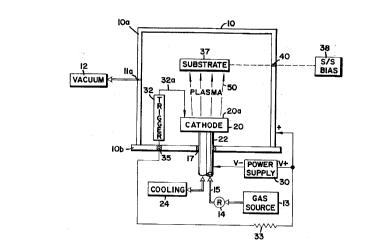
Referring to Fig. 1, there is generally illustrated
at lO a vapor vacuum deposition chamber having a first wall
chamber portion lOa and a second wall chamber portion lOb
appropriately connected together (not illustrated) to form an
enclosed inner cavity 11 that defines a deposition chamber in
which substrates are to be coated. A vacuum pumping system,
diagrammatically illustrated at 12, communicates with the
inner cavity 11 through an outlet port lla of the cavity 11,
and is operable to suitably evacuate the chamber in a manner
well- known by those skilled in the art. Appropriate process
gas source means for inserting reactive or inert process
gases into the inner cavity 11 during the deposition
procedure, are generally illustrated at 13, and communicate
with the inner cavity 11 through a flow control regulating
means generally indicated at 14 and a gas flow path 15 (to be
described in more detail hereinafter).
16
~ J
A source of coating material 20, referred to in
Fig. 1 a~ the ~cathode" represents the origin of coating
vapor or "plasma~ for the vapor deposition coating process,
and represents one electrode of an arc generating apparatus.
In an electric arc vapor deposition system, such source of
coating material generally represents a physical mass of
coating material, in solid form. The physical shape of the
source material can vary from cylindrical, to rectangular, to
irregular in shape, as is well-known to those skilled in the
art. The type of source material can also significantly
vary, from conductive materials such as a metal or carbon to
a material that becomes a conductor as a function of doping
or temperature, such as boron, silicon or germanium, and also
compounds and alloys of the same. In a preferred embodiment
of the invention, the source material is preferably a
conductive metal, and is preferably titanium. The source
material 20 is mounted in the deposition cavity 11 by
appropriate mounting means, generally illustrated at 22 in
the ~rawing, and typically has at least a portion thereof
projecting outwardly through one of the chamber walls to the
atmospheric environment. In the diagrammatic illustration of
Fig. 1, the mounting means 22 is illustrated as projecting
through the second chamber wall portion lOb. Due to the high
electric current levels passing through the cathode during
the electric arc vapor deposition process, the cathode gets
extremely hot, requiring external cooling. Such cooling is
typically provided by water flow through the system, the
supply for which is schematically illustrated at 24 in Fig.
1, which communicates with the cathode mounting apparatus 22
by means of the fluid flow path 16. Appropriate vacuum
sealing and electrical isolation means, generally illustrated
at 17, are provided for maintaining the vacuum within the
deposition cavity 11 and for electrically isolating the
source 20 from the deposition chamber wall portions 10.
A primary power source for generating and
maintaining the electric arc energy of the system i9
illustrated at 30. In the example illustrated, a DC power
source is depicted with its negative terminal (V-)
electrically connected to the cathode source 20, generally
through the cathode mounting means 22. The positive terminal
(V+) of the power supply 30 is directly connected to a
primary anode of the electric arc system. While the anode
may comprise a separate structure within the cavity 11, the
chamber wall often acts as the anode, as is illustrated by
the connection of the positive terminal (V+) to the chamber
wall 10 in Fig. 1. While not illustrated in the figure, the
anode may also be provided with appropriate cooling means, in
manners well-known in the art. It will be appreciated that
other than DC power supplies may be used.
The electric arc is typically initiated within the
deposition chamber cavity 11 by means of a trigger assembly,
generally indicated at 32. The trigger assembly 32 may be of
any .appropriate construction, such as for example the
pneumatically operated trigger apparatus of U.S. Pat. No.
4,448,799, or of any other configuration that is operable to
initiate an arc between the cathode source 20 and the anode
10. Such trigger assemblies typically include a movable
contact rod member, generally indicated at 32a which is
operable so as to move into and out of electrical contact
with the cathode evaporation surface 20a. Electrical power
for initiating an arc on the cathode surface 20a is provided
to the trigger assembly 32 from the (V+) output terminal of
the power supply 30, typically through a resistor 33 and an
appropriate signal flow path such as indicated at 34. The
signal flow path 34 passes through the chamber wall 10b by
means of an insulating seal member, generally indicated at
35. Operation of the arc-initiating trigger apparatus and
the general operation of the arc vacuum vapor deposition
chamber i~ well-known in the art, and will not be further
detailed herein.
Those items to be coated within the chamber 11 are
typically referred to as substrates, and are diagrammatically
illustrated at 37 in Fig. 1. The substrate(s) are
appropriately mounted within the chamber, and may also be
electrically biased, as diagrammatically illustrated by the
substrate bias supply functional block 38, which is
operatively connected to the substrate(s) by means of an
appropriate signal flow path, generally indicated at 39. The
substrate(s) can also be heated (or cooled) by appropriate
heating (cooling) means (not illustrated). The signal flow
path 39 is electrically isolated from the chamber wall lOa by
appropriate electrical insulator and seal means, generally
indicated at 40. It will be understood and appreciated that
the relative spacings between and configurations for
components such as the cathode, anode and substrate(s) in
Fig. are diagrammatic in nature, and are not intended to be
represented to scale or as they would actually appear
relative to one another in an operative system.
The electric arc(s) created and sustained between
the cathode evaporation surface 20a and the anode (inner
walls of the deposition chamber 10) create a plasma 50 which
is outwardly directed from the cathode evaporation surface
20a for engagement with and generally for coating the
substrate 37 or selected portions thereof, as is well-known
in the art. Such plasma 50 includes neutral atoms, molecules
of residual or reactive gas introduced into the chamber 11,
and ionized atoms and molecules. In conventional arc vacuum
deposition processes, the arc(s) also generate a large amount
of macroparticles. Compound coatings are created by
introducing reactive gases into the chamber from the reactive
gas source 13, which gases combine with vaporized material
from the cathode source 20.
fl
The arc terminus or attachment spot which is
~isible on the cathode evaporation surface 20a is typically
referred to as a "cathode spot." One or more such cathode
spots may exist on the cathode surface at a time, depending
upon the level of current in the arc. The size or radius of
such spots vary with the type of source material and the
energy present in the arc. Numerous observations of such
cathode spots have led to the discovery that the cathode spot
terminology actually refers to several significantly
different types of spots (see for example A. Parfenov,
"Concerning the Types of Cathode Spots," IEEE Transactions on
Plasma Science, vol. PS-13, No. 5, 1985.) The observed
cathode spots are generally divisible into two types:
"explosive" spots and "thermal" spots. Explosive spots
represent cyclical operation of explosive emission centers
which leave characteristic traces on the cathode surface
which are microcraters of micrometer or submicrometer size.
Thermal cathode spots differ in essence from explosive
cath~de spots. The thermal spots appear only in a period of
time after the arc discharge has started, and they occur only
in those sites where explosive spots have been operating
until that moment. The thermal spots produce the strongest
cathode erosion and represent the largest source of
undesirable macroparticle generation. In accordance with the
present invention, it has been discovered that the plasma may
be enhanced for conditioning of substrates and the deposition
of coatings by introducing a process gas into the deposition
system in a controlled and unique manner. By such selective
and precise control of the process gas introduction to the
system, the present invention enables the prevention of
formation of slow moving thermal spots even at very high
discharge currents (i.e., about 300 amps) and at very low
process gas flow rates. By thus preventing, or at least
minimizing, the formation of thermal spots on the cathode
evaporation surface, macroparticle generation can be
- minimized and virtually eliminated, even in line-of-sight
cathode/substrate configurations, thereby providing
deposition of smooth and dense coatings on the substrate 37.
The present invention significantly differs from
deposition structures of the prior art such as that of U.S.
Pat. No. 4,929,322 described in the Background section of the
specification, which introduced gases into a "cathode
chamber" formed above the cathode evaporation surface. Such
prior art configuration does not adequately provide for the
introduction and maintenance of process gas at the cathode
evaporation surface, where it is most needed during the
vaporization process in order to prevent the formation of
thermal cathode spots on the cathode evaporation surface and
does not create a process gas activation zone as defined
herein, or provide the other process advantages offered by
this invention.
The arc energy passing through a cathode spot and
into the cathode through the cathode evaporation surface,
trans-forms a portion of the solid cathode material into a
"plasma jet" of material that is forcibly ejected into the
vacuum chamber above the cathode evaporation surface as a
part of the coating plasma. Prior art techniques of reactive
or process gas introduction into the vacuum chamber, even
that such as illustrated in the 4,929,322 patent, have not
been able to effectively force the gas "down" to the cathode
evaporation surface since the plasma jets in effect create a
pressure wave which forces the introduced gases of prior art
structures up and away from the cathode evaporation surface.
In contrast, the present invention ensures that there will be
adequate process gas molecule concentration at the location
where it is most needed, on and immediately above the cathode
evaporation surface. According to a preferred embodiment of
this invention, a process gas is introduced into the
deposition system through the cathode evaporation surface,
thereby ensuring relatively high process gas molecule
21
concentration at the cathode evaporation surface. The ga~
introduction process of this invention creates a process gas
activation region or zone adjacent to the cathode evaporation
surface, thereby creating a high level of ionized and excited
gas species which influences the cathode spot formation and
operations. The process gas activation zone is located just
beyond (as measured in a direction away from and normal to
the cathode evaporation surface) the Langmuir sheath where
the cathode potential voltage drop occurs. For a more
thorough discussion of the Langmuir sheath phenomenon, the
reader is referred to: G.A. Lubimov and V.I. Rakhovskii,
"The Cathode Spot of a Vacuum Arc", Sov. Phys. Usp. 21(8),
Aug. 1978. Activation processes such as ionization and
excitation of atoms or molecules and dissociation of the
process gas molecules takes ~place in the process gas
activation zone created by this invention.
The thickness of the process gas activation zone is
determined by the relative value of the cross-sections for
elem~ntary processes in the near electrode plasma and by the
concentrations of charged particles emitted from the cathode
surface. The thickness of the activation zone is equal to:
h~max ( 1 il e) Eqn. 1
where li, l~, are the mean free paths of the cathode material
ions and electrons in the process gas. These mean free paths
may be determined as:
lie=l/ngaie Eqn. 2
where ng is the concentration of gas atoms or molecules, aie
is the cross-section of the process.
As seen from the definition of the thickness of the
activation zone, its magnitude depends on the specific
combination of the cathode material and the type of process
gas. It should be noted that the process gas can be inert
22
such as Ar, Kr, Xe or reactive such as ~2~ N2, H2, or ga~
compounds such as CH4, C2H2~ etc. In addition, the process
gas can be combinations or partial pressures of the above.
It is necessary to note that the length of the
S process gas activation zone is several orders greater than
thickness of the space-charged layer (Langmuir sheath) which
is estimated as y~min(li lelem) , where li le lem are the
mean free paths of the cathode material ions and electrons of
the plasma and of the emitted electrons, respectively. The
concentration of the cathode material atoms is of the order
of 10l9-102~ cm~3 whereas the concentration of process gas even
in the case of process gas controlled arc is about 10l6-10l7
cm~3 (an additional source of gas molecules in this zone is
the desorption of the process gas from the cathode working
lS surface due to the cathode spots operation). In addition,
cross-sections for elementary processes (ionization for
example) for cathode materials as a rule is more than for
process gases. So the space-charged layer is negligibly
small compared to the process gas activation zone. In this
case, the thickness of this zone may be measured from the
cathode working surface.
This analysis demonstrates one of the main
advantages of this technique in that it allows for operation
of the cathode at high local gas concentration while
depositing the coating at low gas pressure in the chamber.
This increases the concentration of the gas molecules in the
process gas activation zone to 1016-1017 cm~3 which is two
orders of magnitude greater than the concentration of gas
molecules in the near cathode region in the case of the
conventional process.
The processes of ionization and excitation of the
process gas molecules and atoms in the process gas activation
zone occur by way of many mechanisms, but occur primarily
through the mechanisms of charge transfer from highly charged
- cathode material atoms and by means of nonelastic collisions
between plasma electrons accelerated in the Langmuir sheath,
and process gas atoms or molecules (as described more fully
below). The performance of any particular activation
mechanism depends on the specific combination of the cathode
material and on the type of process gas or gas mixture being
used. The process gas activation zone also allows for the
formation of emission-active phase compounds on the cathode
evaporation surface, which influence the binding energy and
decrease the electron work function of the materials, to
minimize or eliminate the formation of thermal cathode spots
on the cathode evaporation surface and the macroparticles
they create. As will be appreciated from the following
descriptions and examples practicing this invention, the
unique method for introduction of process gas into the system
and creation of the plasma gas activation zone provides for
the creation of coating and cleaning plasmas that produce
deposited coatings with superior quality over known prior art
coatings and also facilitates the processing steps required
to fabricate such coatings. For example, the deposition
process can be achieved at relatively low chamber gas
pressure, making effective plasma conditioning of a substrate
possible and which is further enhanced by the types of
energized plasmas that can be created by use of this
invention. This invention further provides for extremely
stable arc operation in a steady-state regime with very low
discharge current and for the deposition of previously
difficult to deposit source materials.
As previously stated, activation of the process gas
within the process gas activation zone is accomplished
through many mechanisms. One of the primary such mechanisms
for process gas activation takes place due to charge transfer
from highly charged ions such as shown in the following
equations:
24
2 ~
,
MZ2+G-M(z~ +G~ Eqn. 3
where M is an ion of the cathode materials, G is the process
gas atom or molecule, and z is the ion charge. These
reactions are the most effective due to high process gas atom
or molecule concentration just near the cathode surface.
This reduces the content of highly charged ions in the plasma
flux and increases the process gas ionization level.
A second important mechanism of process gas
activation is by means of nonelastic collisions between
plasma electrons accelerated in the Langmuir sheath, and
process gas atoms and molecules.
The probability We of the interaction of plasma
electrons with reactive gas atoms or molecules can be written
as:
We-~I2eng<~e(ve) > Eqn. 4
where--ne is the average electron density or concentration in
the process gas activation zone, ng is the concentration of
process gas atoms or molecules in the same zone, ae(Ve) is the
cross-section for the specific process, Ve is the relative
velocity of electron and gas atom or molecule, and ~ ~
denotes averaging over the distribution function. Summation
is carried out over all forms of inelastic interactions.
As is evident from Eqn. 4, an increase in process
gas concentration near the cathode surface is accompanied by
a significant increase in the degree of excitation,
dissociation, and ionization of the process gas molecules,
which sharply lowers the threshold of the nitride (carbide,
oxide, etc.) synthesis reaction and the growth of the
nitrogen (carbon, oxygen and s.o.) content in the coatings.
Therefore, the interrelated influence exerted on the state of
the reactive gas by the interaction processes of the electron
and ion components of the plasma with gas added through the
2 ~
cathode, leads to an avalanche-like increase in the degree of
activation of the reactive gas, rapidly developing into
saturation as the result of the practically complete
dissociation and ionization of the gas. While such gas
activation processes are present to some extent in
conventional arc processes, they are very inefficient in such
prior art systems. However, by introducing the processing
gas into the system as shown in this invention, the degree of
processing gas activation is dramatically enhanced. Further,
the possibility of running the deposition process at low gas
pressure in the vacuum chamber helps to avoid loss of the
charged and excited particles created in the process gas
activation zone, that might otherwise occur (as in prior art
systems) by recombination or disactivation of the charged
particles as they progress through the prior art process gas
present in the chamber from the cathode evaporation surface
to the substrate. Accordingly, this invention provides
significant advantages over conventional prior art arc
depo~ition processes in that it provides for high level of
activation of the process gas species in the process gas
activation zone, and such energized gas species are able to
effectively reach the substrate due to comparatively low gas
pressures in the vacuum chamber.
The physical implementation of the process gas
injection through the cathode proper of this invention may be
achieved by various methods. One means of achieving such gas
injection through the cathode may be accomplished by
manufacturing the cathode material entirely or partially from
a "porous metal" such as illustrated in Fig. 4, wherein the
injected gas permeates under pressure through a system of
capillary canals formed by interconnecting porosity of a
portion of the cathode. Such materials typically referred to
in the art as "porous materials" are commercially available
from such companies as Astro Met, Inc., which market such
materials under the AMPORMAT trade name. Such materials
26
include metals and alloys as well as ceramics and oxides and
can be configured to virtually any porosity/density desired
as for example from porosities ranging from 15~ to 9S~.
Alternatively, the reactive gas may be injected through one
or a plurality of holes formed or drilled through the cathode
or through a system of holes drilled through or formed into
the cathode, such as illustrated in Figs. 2 and 3. Referring
to Figs. 2 and 3, the cathode 20 has a single gas injection
passageway 20b axially formed therethrough and extending from
the cathode evaporation surface 20a and through the material
forming the cathode body, to and through the rear surface 20c
of the cathode. In the configurations illustrated in Figs.
2 and 3, the cathode evaporation surface 20a defines an
axially aligned conically shaped depression that
cooperatively and continuously unites with the passageway 20b
such that process gas injected through the passageway 20b
uniformly continuously flows over and in direct engagement
with the entire cathode evaporation surface 20a, thus
providing an adequate process gas molecule concentration in
the interface between the cathode working surface and the
plasma jets generated by the cathode spots (as generally
indicated by the gas flow lines in Figs. 2 and 3).
The cathode surface temperature may be considered
as a factor which determines the reaction rate of the
erosion-reducing layer formation since the kinetics of
surface reactions strongly depend on the cathode surface
temperature. Therefore, according to two different
embodiments of the invention, the described cathode is
mounted for operation on two different types of cooling
structures for operation in two modes: "cold" (direct cooled
cathode as illustrated in Fig. 2) and "hot~' (indirect cooled
cathode as indicated in Fig. 3). In the case of the "hot"
cathode mode of operation, the cathode's crystalline
structure transformation must be taken into account as well
~ d ~ ~ ~
as the cathode~s surface temperature distribution in the
influence it has on the cathode spot motion.
Referring to Fig. 2, the cathode 20 is illustrated
as secured to the mounting means 22' for operation in the
~'cold" mode. The mounting means 22' has a central spindle
22a' into which is threaded one portion of a stud member 23'.
The mounting member 22' is hollowed out to define an annular
fluid passageway 22b' having inlet and outlet ports 22c' and
22d' respectively that are cooperatively connected in fluid
communication with the fluid flow path 16 (Fig. 1) to the
primary cooling source means 24. That portion of the annular
fluid passageway 22b' which addresses the "backl' surface 20c
of the cathode 20 is open and provides direct fluid flow
engagement with the back surface 20c of the cathode 20. In
the preferred embodiments illustrated in Figs. 2 and 3, the
cooling fluid is preferably water. The stud member 23~ is
threaded into the cathode 20 through its back side 20c as
illustrated in Fig. 2 such that the back surface 20c of the
cathode 20 forms a tight seal with the annular outer edge of
the mounting means 22e' and the corresponding upper surface
of the central spindle 22a'. The seal for the annular fluid
passageway 22b' is closed and maintained with the lower
surface of the cathode 20c by means of a pair of O-rings 22f'
and 22g'.
A lower stud member 25 defining an internal axial
passageway 25a is threaded into the lower portion of the
central spindle 22a' to form an axial extension thereof. The
central spindle 22a' defines a central axially aligned
passageway 22h', and the threaded stud member 23' also
defines an axial passageway 23a' formed therethrough. The
axial passageways 25a', 22h' and 23a' are commonly sized and
aligned so as to provide a continuous fluid flow passageway
from the lower portion of the lower stud member 25 to the
fluid passageway 20b formed in the cathode 20. A cylindrical
sleeve member 26 is secured within the common passageway
28
? ~
defined by 25a', 22h' and 23a', as indicated in Fig. 1, to
provide a sealed gas flow passageway through the lower stud
member 25, the central spindle 22a' and the upper stud 23.
The sleeve member 26 is connected in fluid communication with
the fluid flow line 15 (Fig. 1) to receive a pressurized
supply of process gas from the primary gas supply means 13.
A preferred configuration for mounting the cathode
20 for operation in a hot mode, is illustrated in Fig. 3.
Referring thereto, the configuration is very similar to that
of the cold mode mounting configuration of Fig. 2, except for
the fact that the lower surface 20c of the cathode is not in
direct fluid communication with the cooling source fluid, and
thermal contact of the cathode with the cathode holder is
minimized. In the hot mode cathode holder configuration
illustrated in Fig. 3, the upper surface of the annular fluid
passageway 22b'' is completely closed by the lateral
extension of the central spindle 22a'' as indicated. In this
cathode mounting configuration, the entire upper surface
22e'' of the central spindle 22a'' forms a seat for the lower
surface 20c of the cathode 20 and provides cooling thermal
transfer to the cathode through the material of the enlarged
central spindle 22a'', which in turn is in fluid
communication with the cooling fluid passing through the
annular fluid passageway 22b''. In other respects, the
cathode mounting structure of the hot mode mounting
configuration of Fig. 3 is the same as that previously
described with respect to the cold mode mounting
configuration of Fig. 2. The lower surface 20c of the
cathode 20 may be threaded down by means of the stud 23''
into direct engagement with the upper surface 22e' of the
central spindle 22a'', or may be slightly axially spaced
therefrom as is illustrated in Fig. 3.
In the case where the cathode or portion thereof is
manufactured from a porous material such that the process gas
can be directly injected through the capillary canals formed
29
through the cathode material itself, the cathode mounting
configuration could include a sealed manifold in direct fluid
communication with the back surface 20c of the cathode,
wherein the manifold is also in direct fluid communication
with the gas supply line 15 leading to the primary process
gas supply 13. Alternatively, the cathode may be configured
to provide the gas distributing manifold 2Od as illustrated
in Fig. 4 wherein an insert of porous cathode material 20e is
configured to cooperatively overlie the manifold portion 20d
such that process gas introduced into the manifold 20d
through the sleeve 26 and passageway 20b' flows through the
capillary canals of the porous insert material to and through
the upper cathode evaporation surface 20a' which is formed on
the surface of the porous, cathode material.
The apparatus and methods of this invention,
therefore, suggest a new technique for reducing
macroparticles, for increasing the deposition rate, for
simplifying the coating process and for improving the quality
of the deposited coating. The method of this invention has
been coined by the inventors as the "Gas-Controlled Arc"
process, or the GCA process. This method is based in part on
the creation of emission-active phases on the cathode surface
and changing the character of a cathode spot's motion by
changing the melting point of surface layers of the cathode's
material and its work function. The process gas used can be
reactive, nonreactive, or a combination of such gases or
vapors, depending upon the material being deposited. For
example, process gases such as nitrogen, argon, oxygen,
hydrogen, hydrocarbons, krypton, xenon, etc., could be used.
By way of example, the present invention is realizable in a
reactive arc deposition process in which reactive gases are
added to a vacuum chamber for synthesis combinations of the
reactive gases with transition metals. It is known that
depending on dimensions, properties and quantity,
microroughness and various inclusions on the cathode surface
~ ~ ~? ~
may help to increase the rate of cathode spot migration, and
may also help localize them to become confined to a definite
part of the cathode surface. Different regimes of arc
burning may occur depending on the dimensions of emission-
active phase inclusions, and their quantity. For example,during deposition of titanium nitride and other complex
coatings (such as oxides, carbides, oxi-carbo-nitrites of
transition metals), formation of these emission-active phases
on cathode surfaces has been found. A work function of
titanium nitride (TiN) is 2.92 eV, as compared with a work
function of 3.95 eV for pure Ti. The melting point for TiN
is 2700~ C; whereas for Ti, the melting point is only 1600~
C. Therefore, by the formation of films on the cathode
surface, it is possible to increase the binding energy and
decrease the electron work function - and in so doing, change
the type of cathode spots which exist on the evaporation
surface of the cathode.
The present invention actually creates a film of
an emission-active phase (TiN in the case of a titanium
cathode and nitrogen process gas) on the cathode surface,
thereby reducing the erosion of cathode material,. This is
made possible by the presence of a rather high concentration
of process gas in the process gas activation zone during the
deposition process (about 5-10 mTorr). Such selective
"poisoning" of the cathode surface, only in the process gas
activation zone, while maintaining the process gas pressure
in the remainder of the deposition chamber at a low value,
has not been possible with the use of prior art arc
deposition techniques. It is known, for example, that a
titanium cathode surface will poison in the presence of a
reactive gas such as nitrogen at a pressure of about 5-10
mTorr. It is well-known that such poisoning is also
dependent upon other parameters, such as working surface area
and cathode current. But such high gas pressure, if extended
to the entire deposition chamber, as would be required of
31
~ ~a ~ ~ ~ a
prior art techniques, critically decreases the deposition
rate. Such high gas pressure throughout the chamber also
makes ion bombardment of the substrate surface in the
presence of the process gas all the more impossible due to
increased collisions with the process gas atoms between the
cathode and substrate, and oxygen contamination and arcing on
the substrate surface. Accordingly, such prior art
techniques attempting cathode poisoning and subsequent
coating of substrates have led to inconsistent coating
quality. The present invention allows for the selective
introduction of a large process gas concentration only "at~'
and immediately adjacent the cathode evaporation surface
(i.e., only in the process gas activation zone), and for
rather low gas pressures throughout the rest of the vacuum
chamber, and particularly between the cathode and substrate
surface to be coated. According to a preferred embodiment of
the invention, this is accomplished by injecting the process
gas "through" the cathode, such that it actually flows
through the cathode surface.
It is important, to ensure an adequate supply of
process gas flow through the cathode surface. It is well-
known that cathode spots generate very dense plasma jets,
which prevent process gas dlffusion (according to prior art
methods) back toward the cathode surface region from the
deposition chamber. These dense plasma jets work like
"plasma pistons~' which normally pump process gases introduced
into a deposition chamber away from the cathode surface
region. The present invention overcomes this shortcoming of
prior art systems. In the present invention, the process gas
flow rate required in the process gas activation zone is
determined as a function of the arc discharge current,
according to the following relationship:
Q/I2( Qcr) =~ Eqn. 5
e~
where Q is the flow rate in sccm, I is the arc discharge
current in amperes, Qcr is the critical value of process gas
flow rate for standard arc discharge current of 100 amperes,
I~ is the standard discharge current and ~ is a parametric
factor related to a current range. For titanium, and an ion
current range of up to 250 amps, r may be accepted as 1. For
wider range of different materials and different current
levels, ~ would have to be adjusted appropriately as is well-
known by those skilled in the art. The magnitude of the
constant ~ depends on a combination of cathode material and
the type of process gas. In a case of a titanium cathode and
nitrogen, ~ equals 0.2. The fulfillment of this condition
assures the appropriate type of cathode spots on the cathode
evaporation surface, and therefore a proper coating
smoothness. The critical flow rate is the process gas flow
which provides effective cathode surface poisoning at any
value of chamber evacuation pumping speed, while evacuating
or pumping gas from the vacuum chamber, to maintain a
predetermined pressure within the vacuum chamber (outside of
the process gas activation zone).
In the cathode configurations practicing this
invention such as shown in Figs. 2 and 3, wherein the process
gas is introduced through a channel in the cathode, the
cross-sectional diameter of the process gas flow channel in
the cathode that would be required to deliver adequate gas
flow to accomplish the purposes of this invention is defined
by Equation 6:
Re= (4mp) / (~K~TD) Eqn. 6
wherein Re is the Reynolds number, m is the mass of the
molecule, ~ is the viscosity of the gas, Q is the gas flow
rate, K is the Boltzman's constant, T is the gas temperature,
and D is the diameter of the gas inlet channel (where all
parameters are given in international units).
~ 7 (~ 5 ~I,
A more complete appreciation of the principles of
this invention will be apparent from a review of the
following experimental tests that were performed practicing
the GCA process of this invention.
Comparative Coatinq ProPerties
A comparison investigation of the coating
properties achieved using the inventive GCA process and a
regular or conventional arc process was conducted, with a
comparative evaluation of the following properties: coating
smoothness, deposition rate, microhardness and adhesion. To
compare the two processes, and to elucidate the advantages of
the GCA process over the conventional arc process, the
titanium-nitrogen (Ti - N2) system which is well understood,
was used as a comparative system. The process gas flow and
arc current were the same ~for both the GCA and the
conventional processes. The GCA process was realized in two
operational modes - with the "cold" and the "hot" cathode
regimes. TiN coatings were deposited onto HSS coupons with
the,,same deposition conditions but with the different
deposition techniques. The only difference between them was
in the way the N2 process gas was introduced into the system.
For the GCA process, the process gas was introduced through
an inlet placed in the middle of the cathode working surface,
as indicated in Figs. 2 and 3 for the "cold" cathode and
"hot" cathode regimes respectively. For the conventional
process, the process gas was introduced to the vacuum chamber
through an inlet in a wall adjacent to the cathodic system as
has been typically done in prior art systems. The results of
these experiments are presented in Table 1.
Table 1
CONVENTIONAL GCA PROCESS
ARC PROCESS
** ***
"COLD" CATHODE "HOT" CATHODE
FILM 540-850 160-170 160-240
ROUGHNESS, RA,
A
DEPOSITION 0.06* 0.2 0.3
RATE, ~m/min
MICRO 2800-2900 3900-3950 4000-4050
HARDNESS,
Hv, N/mm2
SCRATCH TEXT, 75-80 75-85 85-90
U.C.L.,N
* Deposition process was carried out at a nitrogen pressure
of about 10 mTorr in the vacuum chamber. This regime was
chosen to provide high quality coatings using prior art
techniques, which minimized coating roughness (850A) and to
provide high coating microhardness (2800-2900 N/mm2).
** The integral cathode surface temperature during the
deposition process was between 600-650~C.
*** The integral cathode surface temperature during the
deposition process was between 1600-1800~C.
Figures 5a and 5b illustrate scanning electron
micrographs taken respectively of the surfaces of the
coatings produced above according to the GCA arc process and
the conventional arc deposition process. As can be readily
observed from the illustrations, the GCA process produced
coating surface (Fig. 5a) does not have the large defects
(correlating with the roughness measurements of Table 1) or
the "ripple" effects visible on the coating surface (Fig. 5b)
produced by conventional arc deposition techniques.
Similarly, scanning electron micrographs from fracture cross-
sections of the coatings produced by the GCA and conventional
arc processes (Figs. 6a and 6b respectively) illustrate the
improved surface characteristics produced by the GCA process.
2 ~ d
It should be noted that the results produced in these
experimental tests were conducted in line-of-sight
configurations between the cathode evaporation surface and
the substrate, and without the use of any magnetic fields,
and that even better results might be obtained by combining
the principles of this invention with other known coating
enhancement techniques.
As is evident from Table 1, the coating properties
are superior for both of the GCA (hot and cold cathode
regimes) processes over those of the prior art convent-ional
arc technique. The results are sufficient to allow a
definite conclusion that in the case of the inventive GCA
process, the generation of macroparticles is significantly
reduced and improved coatings are possible as compared to the
regular or conventional arc deposition process.
Erosion Rate Measurements
It is known that the erosion rate for cathode
degradation during the arc deposition process is defined as
the relationship between the change in a cathode's mass
according to the amount of conducted charge, as shown in
Equation 7:
~m=~I~t Eqn. 7
where m is the mass of the cathode, K iS the erosion rate, I
is the arc current and t is time.
In order to determine optimum process gas flow, the
gas flow was varied from 15 sccm to 160 sccm. Tests were
conducted for both the GCA process and for the conventional
arc deposition process. In each test, the steady state
process gas pressure corresponding to the value of the gas
flow was monitored by a vacuum meter. The measurements were
performed by determining the mass of the Ti cathode before
and after evaporation for 30 minutes at an arc current of 100
amps. The results of this testing is illustrated in Fig. 7
which shows the erosion rate versus the nitrogen process gas
flow curves for both the conventional arc deposition and the
GCA processes. This graph emphasizes dramatic difference
between the two processes.
Comparative Gas Pressure vs. Flow Rate
The relationship between the nitrogen process gas
pressure and the N2 flow rate for a 100 amp discharge current
was tested for both the conventional arc deposition process
and for the GCA process. The resulting curves are plotted in
Fig. 8 for the conventional arc deposition process using a
new dished cathode, and in Fig. 9 for the GCA process. In
Fig. 8, the gas is being introduced to the chamber int he
conventional manner; whereas in Fig. 9, the process gas is
being introduced into the system through the cathode, as
previously described. In Figs. 8-10 the "O" designations
represent plots of the experimental results as process gas is
being introduced to the system to increase the pressure;
whereas the "o" designations represent plots of the
experimental results as gas is being withdrawn from the
system to reduce pressure. A comparison of the results of
the Figs. 8 and 9 plots illustrates the fact that in the case
of the GCA process, the formation of a TiN layer on the
cathode surface occurs at a lower flow rate. Variation of
the pumping speed by means of a throttle showed that there
was not a significant difference in cathode erosion rate when
gas flow rate Q 2 Qcr~ where Qcr is the critical flow rate
from Equation 4. This demonstrates that due to the process
gas introduction through the cathode surface, even a low gas
flow rate provides the needed concentration of gas molecules
in the interface between the cathode surface and the
quasineutral plasma (i.e., in the process gas activation
zone). Therefore, with the inventive GCA process, process
gas flow is not a limiting factor for the desired chemical
reaction to occur on the cathode surface.
37
Surface Morphology ComParisons
In this regard, it is interesting to compare
scanning electron micrographs of surface morphologies of the
cathodes that were used in the above testing with different
process gas flow rates. The surface morphology photographs
of these cathodes are illustrated in Figs. 13 through 18.
Figs. 13 and 14 are photographs of the surfaces of
conventional cathodes that operated in cold and hot modes
respectively for process gas flow rates of 20 sccm. Fig. 15
is a photograph of the conventional cathode that operated in
a cold mode at a gas flow rate of 120 sccm. Figs. 16 and 17
are photographs of the surface morphology of cathodes
configured according to the principles of this invention that
operated according to the GCA process in a cold mode regime
for process gas flow rates of 120 sccm and 20 sccm
respectively. Fig. 18 is a photograph of a cathode operated
according to in the GCA process in a hot mode regime with a
process gas flow rate of 20 sccm. Film composition,
including nitrogen concentration, was determined by EDX in
the scanning electron microscope. The results of analyses
show that the titanium nitride layer is about stoichiometric
within the accuracy of the measurements (5~). The surface
morphology photographs are interesting in illustrating that
even at flow rates of 20 sccm, the cathode surface of a
cathode used in the GCA process (Fig. 17) is not melted to
the degree of the cathode used in the conventional arc
deposition process (Fig. 13).
Measured Discharqe Arc Voltace Dro~ vs. Gas Flow Rate
The process of formation of a layer on the cathode
surface with a low work function and higher melting point
(which can be referred to as the "erosion-reduction layer")
was monitored by measuring the discharge arc voltage drop in
the GCA system. The discharge arc voltage drop for the
titanium cathode GCA process system was measured as a
function of the nitrogen flow. These results are graphically
38
~ '7 ~
illustrated in Fig. 10. The results show that the discharge
arc voltage drop is very sensitive to the presence of the
erosion-prevention layer, and may be used for process control
and diagnostics. The results show that the GCA process has
a very high affinity for the formation of the erosion-
prevention layer. The erosion-prevention layer forms at very
low process gas flow rates, and gives rise to the possibility
of running the deposition process at very low input gas
pressure, thereby reducing macroparticle generation at the
same time as improving the deposition rate.
Spectral Measurement Comparisons
Spectral measurements of the arc discharge in the
vicinity of the cathode surface (i.e., at 20 mm therefrom)
were carried out at various nitrogen flow rates (0-60 sccm)
for cathodes used in both the GCA process and in the
conventional arc deposition process. These results are
graphically illustrated in Figs. 11 and 12. Fig. 11 shows
the relative intensity variations of a titanium spectral line
(TiI, ~ = 5210 A) as a function of nitrogen flow rate at a
cathode current of 100 amps. Fig. 12 shows the relative
intensity variations of an N2~ spectral line (N2II, ~ = 3914
A) as a function of nitrogen flow rate at a cathode current
of 100 amps. As previously observed for the cathode surface
erosion rate, the titanium spectral line intensity decreases
around or at the same gas flow rate at which formation of the
erosion-reduction layer takes place. This fact directly
confirms that thermal cathode spots which generate too much
metal neutral vapor, transform to fast moving explosive
cathode spots. The explosive cathode spot generates much
less neutral metal vapor and more ionized atoms. Reduction
of neutral particles in the plasma flow is very beneficial
~or the deposition of dense coatings with no porosity.
Accordingly, the GCA process of this invention demonstrates
an obvious advantage compared to conventional processes.
Referring to Fig. 12, it will ~e noted that the spectral
39
7 ~ ~ ~
r
intensity of the N2~ line increases sharply at the process gas
flow rate corresponding to the TiN layer formation on the
cathode surface. At low gas flow rates, the GCA process
demonstrates an advantage in generating nitrogen molecular
ions.
Exam~le Coatin~s
The inventive process provides several unique
capabilities for the direct synthesis of multicomponent gas
and metal compound and ternary coatings since it makes it
possible to realize a steady vacuum arc discharge with large
amounts of cathode materials, with low concentration of
macroparticles in the plasma jets. For example, there have
been serious problems in the deposition of smooth coatings
using aluminum cathodes because the arc discharge is not
stable on the cathode surface,-and the vacuum arc generates
a large amount of droplets or macroparticles. However, using
the GCA process of the present invention, there is no problem
in obtaining a steady vacuum arc with the aluminum cathode
and nitrogen gas flow through a hole in the cathode. The
formation of the aluminum nitride film on the cathode surface
changes the character of the cathode spots and their motion,
drastically reducing macroparticle generation. Further
introduction of the process gas through the cathode gas inlet
channel makes the arc discharge very stable. Accordingly,
the principles of this invention enable the direct synthesis
of (TiAl)N using two cathodes of pure aluminum and pure
titanium, instead of using very expensive composite TiAl
cathodes made by using powder metallurgy technology.
The method of this invention also provides the
possibility to improve mechanical properties of the coatings
due to activation of the process gas. The microhardness of
the coatings, being sensitive to the phase composition and
structure of the materials, characterizes the generalized
value of the plastic resistance due to both the nitrogen
3S content in the condensate and the distinctive features of its
structure. The GCA processes' high degree of activation of
the process gas also offers the prospect of deposition of
complex coatings without any bias. Experiments have
demonstrated the possibility of deposition of TiN on plastic
and glass substrates without DC or RF bias on the substrate,
with good adhesion.
Three example coatings made according to the
principles of this invention were deposited according to the
following examples.
ExamPle #1
A TiN coating having--extremely high microhardness
was deposited according to the GCA process. The deposition
parameters and coating properties for this coating are
illustrated in the first column of Table 2.
Example #2
It is well-known that the coatings deposited with
the aluminum cathode in the conventional arc process appear
to be very rough. The roughness occurs as a result of the
aluminum cathode emitting large numbers of macroparticles.
Using the GCA deposition process, aluminum nitride coatings
were successfully deposited with a very high grade of
smoothness. The deposition parameters and coating properties
for the AlN coating are illustrated in the second column of
Table 2.
Example #3
As mentioned above, the present invention provides
the possibility of direct synthesis of (TiAl)N using two
cathodes from pure aluminum and pure titanium instead of
using very expensive TiAl cathodes made by powder metallurgy
technology. An (TiAl)N coating was deposited according to
the GCA process of this invention using two cathodes from
pure titanium and pure aluminum. The deposition parameters
and coating properties for this coating film are given in
column three of Table 2. As is evident from the Table 2
results, the coating properties for the coatings made with
41
~ ~ ~ 7 ~ ~ ~
the GCA process are superior as compared to conventional arc
processe~ using composite TiAl cathodes.
Table 2. Deposition Parameters and Coating Properties.
5 Parameter Example 1 Example 2 Example 3
Coating TiN AlN (Ti,Al)N
Composition
Substrate HSS M2 HSS M2 HSS M2
Cathode Ti Al (#l) = Ti;
10 Composition (#2) = Al
Spatial 25 25 25
Standoff, cm
Chamber 2 2 3.1
Pressure,
15 mTorr
N2 Flow Rate, 120 120 through the
sccm evaporator
(Xl) 100;
through the
evaporator
. (#2) 100
Arc Current, 100 100 evaporator
Adc #1-100
evaporator
#2-100
Substrate -150 -50 -150
Bias, V
Substrate 400 400 400
Temperature,
~C
Deposition 0.3 (without 0.05* (d.c. 0.15 (with
Rate, ~m/min rotation) bias) rotation)
Roughness, RA, 160-240 200-220 180-190
Microhardness, 4000-4050 n/a 5500-5600
30 Hv, N/mm2 (nanolayer
structure)
42
3 ~ ~ Q
* For comparison of the deposition rate with the deposition
rate of other conductive coatings it is necessary to use R.F.
bias because of semiconductor properties of AlN.
From the foregoing description, it will be
appreciated that coatings deposited according to the gas
controlled arc deposition process of this invention include
the following desirable characteristics as compared to
conventional arc deposition processes:
(1) Very low surface roughness due to reduction
of macroparticles in plasma flow. For
titanium this amounts to greater than five
times reduction. For other metals, an order
of magnitude is possible.
(2) High density coatings due to minimization of
the neutral component of the cathode material
and the process gas.
(3) High microhardness of the coatings (such as
nitrides of the transition metals), due to
_ the following:
- (a) high coating density due to the
reduction or elimination of porosity caused
by macroparticles;
(b) less metallic neutral species being
incorporated into the film; and
(c) the ability to deposit films at low
chamber gas pressure leading to a more J
energetic deposition process, thereby
improving density; and
(4) Improved control of crystallographic
properties of coatings such as:
(a) film texture or orientation of crystal
structure; and
(b) grain or crystal size.
It will be appreciated that while the present
invention has been described with reference to particular
43
embodiments and configurations of cathode structures, manners
of introducing the processing gas and cooling regimes
therefor, various alternative embodiments, design options and
variations thereof will be apparent to those skilled in the
art. Further, while the invention has been described with
respect to its application in depositing certain materials as
exemplified by the preferred embodiment descriptions and
examples, and with certain types of process gases, the
invention is not to be limited to such examples or to such
process gases. It will also be appreciated that the
principles of this invention can readily be incorporated with
or into arc deposition systems that use other plasma and
coating enhancement techniques and methods, to further
improve upon such existing systems. For example, magnetic
fields may be used to further enhance the plasma generation
in manners well-known int he art. Also, the invention could
be used with nonline-of-sight deposition systems such as the
curvilinear or steered arc type of systems. These and other
poss~ble applications for the invention will be readily
appreciated by those skilled in the art. Accordingly, The
invention is not to be limited by any of the particulars of
the preferred embodiments used to describe the invention, but
only by the scope of the appended claims.
44