Note: Descriptions are shown in the official language in which they were submitted.
~2~90 6
WO 96118038 PCTtUS95/lS663
LINEAR PERISTALTIC PUMP
WITH RESHAPING FINGERS INTERDIGITATED
WITH PUMPING ELEMENTS
TECHNTCAL FIELD OF THE INVENTION
The present invention relates to a linear peristaltic pump for providing adjustable
volumetric flow through a flexible fluid-filled tubing, such as with infusion, of intravellous
solutions through a flexible IV tubing. Particularly, the invention relates to a pump
having plurality of pumping elements or plungers which operate sequentially and
repeatedly along a portion of the flexible fluid carrying tubing to squeeze the fluid
therealong with a "milking" type of action. Fluid is forced through the tubing from the
entry end to the output end in the direction of the sequential actuation of the pumping
elements. The volumetric flow rate is adjusted by rh~nging the rate of sequential and
repeated squeez1ng.
~o~o ~
WO 96/18038 PCT/US9~/15663
BACKGROUND OF THE INVENTION
Traditionally intravenous infusion has been accomplished using gravity flow
systems or drip regulated systems. Modern advances for regulating intravenous infusion
have included various types of volumetric pumping systems. In situations where a~patient
5 iS already established with a gl~vi~y-fed or drip-type IV, it often becomes helpful to
convert the same system into one with a pump-controlled volumetric flow. For example,
an emergency IV can be established in the field by paramedics, and upon arrival at a
hospital, a doctor may need to a~minister me~ic~tion at a precisely controlled flow rate.
The same IV tubing system can then be conveniently adapted for controlled volumetric
0 flow pumping through the use of various types of peristaltic pumps which engage the
exterior of the established IV tubing. The typical IV tubing is made of a medical grade
polyvinyl chloride (PVC) which has thin walls and is both flexible and resilient. Other
more expensive tubing has been proposed to reduce collapsing, but at a cost of about ten
times as much as PVC tubing. Alternatively, a combination of types of tubing has been
15 proposed, such as silicon tubing spliced along a length which will be subjected to
peristaltic pumping action. Such combination systems can also have a cost significantly
greater than PVC (about five to eight times as much), because of the materials, splicing
and additional sterilization required. Pumps which act upon the outside of the tubing
walls to pump fluid within the tubing at a controlled rate permit the medical practitioners
20 to avoid disturbing existing catheters or needles already established into the patient.
Thus, various types of modern pumps have been used for pumping fluid through
an IV tubing, including pumps with a rotating arm, with rollers affixed at both ends of the
arm. The rollers are positioned adjacent a curved IV holding channel to engage and roll
along a section of tubing placed into the holding ~h~nn~l, thereby advancing a column of
25 liquid therethrough. As the arm rotates, the rollers alternately engage the tubing, one
behind the other, and successive columns of liquid are moved through the tubing.Rotation of the arm continues and repeats the pumping action.
Another type of pump is one which is referred to as a single-plunger peristalticpump. This type of pump has an entry valve which compresses the tubing shut at an
30 upstream point. A single elongated plunger then squeezes a predetermined length of the
WO 96/18038 2 2 0 ~ 9 0 6 PCT/US95/15663
tubing along a linear section ahead of the closed entry valve. An outlet valve then
compresses the tubing downstream from the elongated plunger after the liquid in the
linear section is squeezed out and moved toward the patient. With the outlet valve closed,
the entry valve is opened and the elongated plunger is retracted to allow fluid to move
5 back into the linear section between the entry valve and the outlet valve. The entry valve
is then closed, and the outlet valve is opened so that compression of the single elongated
plunger can pump more fluid through the tubing.
Another type of pump, which is referred to here as a linear peristaltic pump, uses
a series of pumping ~lementc which each engage and sequentially compress a plurality of
lC small segments along an engaged portion of the IV tubing. Each pumping element in
sequence at its m~imum stroke acts as a seal valve to prevent unwanted reverse flow.
Separate inlet and outlet valves are not required in such a linear peristaltic pump. The
sequence repeats, and the pumping element reciprocating strokes are typically timed to
repeat the milking cycle without interruption. The rate of flow is controlled by ~h~nging
5 the rate of reciprocation while the m~gnitude of the stroke is constant.
With each of the various t,vpes of peristaltic pumps described above, the IV tubing
is repeatedly collapsed to force the fluid out of the tubing in one direction and then
released to allow fluid to reenter from the other direction. After a period of use, the PVC
tubing material becomes progressively fl~ ne~l and perm~n~mly deformed such that the
20 walls become creased and the interior volume of the tubing changes over the normal time
period of operation. Tubing subject to permanent deformation reduces the pumpingefficiency and reduces the accuracy of the pump. To the extent that attempts at reshaping
may cause additional crease lines, the risk of premature cracking, tearing or rupture may
also be increased, particularly at crease lines. Thus, the tubing must be changed frequently
25 and must be carefully monitored to avoid lost efficiency, inadequate flow, inaccurate and
improper volumetric flow or other failure of the system.
22 ~ ~ ~0 6
WO 96/18038 PCT/US95/15663
SUMMARY OF THE INVENTION
The present invention provides advantages of a linear peristaltic pump and
overcomes many of the difficulties which arrive with other types of peristaltic pumps.
The use of a linear peristaltic pump with a plurality of sequ~n~i~l]y actuated elem~nts does
5 not require separate entry and outlet valves as with the single plunger type of peristaltic
pump. The present invention further provides reshaping fingers, which engage a flexible
fluid-filled tubing, such as an IV tubing, adjacent to each pumping elemPnt contact point,
thereby continuously returning the tubing to a constant internal volume and thusm~int~ining a constant flow rate during operation at a given speed. The time of operation
0 before the tubing becomes permanently deformed is increased. A plurality of pairs of
interdigitated reshaping fingers are used and are sequentially actuated transverse to the
actuation direction of the pumping elements along the engaged length of the tubing. The
interdigitated positioning of the reshaping fingers with the pumping elements
advantageously facilitates reshaping of the tubing immediately adjacent each of the
15 compression elements so that reshaping of the tubing is effectively accomplished. Further,
the present invention provides pairs of opposed reshaping fingers, each having concave
jaws which the shape of a cylindrical arc m~tching the outside diameter of the flexible
tubing. The unique arc shape of the jaws, and particularly a substantial arc of more than
about 90, is made possible by the interdigitation of the fingers with the pumping
20 elements so that reshaping does not interfere with the pumping elements. The result is
to round the tubing to its original ~im~n~ions without adding additional stress or fatigue
and without callcing additional potential rupture corners.
~2Q1Q0 6
WO 96/18038 PCT/US9511S663
BRIEF DESCRIPTION OF THE DRAWINGS
The foregoing objects, advantages, and features, as well as other objects and
advantages, will become more apparent with reference to the description and drawings
below, in which like numerals represent like Plem~nts and in which:
FIG. 1 is a schematic perspective view of one example of an operational control box
for a linear peristaltic pump, depicting an example of the invell~;ve pumping and reshaping
merh~nism, shown mounted in the control box at a position for engagement with an IV
tubing according to the present invention;
FIG. 2 is a schematic perspective, partial cutaway view of an example of the
0 inventive pumping and reshaping me~h~nicm, including a plurality of pumping elem~nts,
which, in this embo~liment, are in the form of pumping element plates and with
interdigitated reshaping fingers and variable-speed drive motor according to the present
mventlon;
FIG. 3 is a top schematic plan view of a portion of the pumping and reshaping
me~.h~ni.cm of FIG. 2 showing a plurality of pumping ~lem~nt plates and intercligitaterl
reshaping fingers according to the present invention;
FIG. 4 is a c~h~m~tic perspective view of a plurality of pumping element plates and
a plurality of interdigitated reshaping fingers as in FIG. 3;
FIG. 5 is a partial s~.hem~tic cross-sectional view taken along section lines 5-5 of
FIG. 3 showing a plurality of seqll~nti~lly actuated elements and reshaping fingers in
which middle ones of the pumping element.c are shown actuated to compress a flexible
tubing and in which end ones of the interdigitated reshaping fingers are shown actuated
to reshape the flexible tubing at points adjacent to retracted end pumping elements;
FIG. 6 is a schematic end view showing one pumping element plate in a retracted
position so that the flexible tubing is opened at that point and showing the position of an
adjacent pair of reshaping fingers (partially shown with hidden lines) engaged with the
flexible tubing when it is released by the pumping element to reshape it to a circular cross-
section, corresponding to an opened position in a pumping sequence;
FIG. 7 is a schematic end view of the pumping element plate and adjacent pair ofreshaping fingers of FIG. 6 shown in a subsequent partially compressed position in the
2~ 0 ~ 9~ 6
WO 96/18038 PCT/US95/15663
pumping sequence;
FIG. 8 is an end view of the pumping elçment plate and adjacent pair of reshaping
fingers of FIGS. 6 and 7, shown with the pumping elçment in a fully compressed position
during the pumping sequence so that the tubing is closed and the adjacent pair of
reshaping fingers are completely retracted from the tubing according to one embodiment
of the present invention; f
FIG. 9 is an end view of the pumping element plate and reshaping fingers of FIGS.
6, 7 and 8 shown with the pumping element in a partially retracted position and with the
reshaping fingers shown partially actuated to engage with the tubing for reshaping;
o FIG. 10 is an end view of an alternative embodiment of a pumping element plate
and reshaping fingers shown in a position in which said pumping element is retracted and
said reshaping fingers are fully actuated into reshaping engagement with a flexible tubing;
FIG. 11 is a end view of the pumping element and reshaping fingers of FIG. 10
shown in another sequential pumping position;
FIG. 12 is an end view of the pumping plate and reshaping fingers of FIGS. 10 and
11 shown in yet another pumping position; and,
FIG. 13 is a end view of the pumping element plates of FIGS. 10, 11, and 12 shown
in yet another sequential pumping position according to the present invention.
a2 019~ 6
WO 96118038 PCT/US95115663
DETAILED DESCRIPTION OF THE PREFERRED EMBODIMENTS
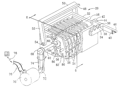
FIG. 1 depicts a sçhem~tic perspective view of an example of one preferred
embodiment of a linear peristaltic pump control box 10, having a control panel 11 with
J control buttons 12, control display 13 and 14 and indicator lights 15. The nature and
arrangement of the control panel display buttons and in~lic~tors can be as shown in FIG. 1
or in other configurations as may become desirable. The linear peristaltic pump control
box is constructed to releasably engage a flexible tubing 16 along an engagementpathway 18, which is conveniently located along one exl:erior surface 19 of the linear
peristaltic pump control box 10. Also, schematically depicted is one preferred
o embodiment of a pumping ~lement and reshaping finger assembly 20, ~tt~ched to control
box 10 and positioned along the engagement pathway 18 in exterior surface 19 of the
control box 10. The pumping element and reshaping arm assembly 20 may
advantageously include a housing 22, which housing 22 is preferably constructed for
attachment within the pump control box 10 or may be integrally formed as part of the
control box 10. The housing typically takes the shape of a box having sidewalls, ends and
a bottom, as will be discussed more fully below.
In the preferred embo~iment depicted in FIGS. 1 and 2, the pumping element and
reshaping finger assembly 20 includes a plurality of pumping elements 24 and a plurality
of reshaping fingers 26 which are inter~ligitaterl between each of the plurality of pumping
elements 24. The pumping elements 24 and the interdigitated reshaping fingers 26 are
preferably constructed as flat, pumping plates 24 and flat reshaping fingers 26,respectively. In the embodiment shown, each of the plurality of the pumping element
plates 24 has an upper element cutout 30, which allows the flexible tubing 16 to fit
thereinto. The cutouts 30 of the pumping elements are ~ligne~l to define an engagement
2j channel 28 aligned with engagement pathway 18. Also, the plurality of interdigitated
reshaping fingers 26 include pairs of opposed fingers 26i and 26ii, which are aligned in
planes between each of the pumping element plates 24. The pairs of opposed
inter~igit~te~ reshaping fingers 26i and 26ii each have corresponding opposed jaws 32i and
32ii. Each pair of opposed jaws preferably defines a substantially cylindrical opening
having a ~i~meter corresponding to the diameter of the flexible tubing 16.
2Z ~ ~ 90 6
WO 96/18038 PCT/US9S/15663
In the preferred embodiment, there is a plurality of pairs of fingers along the
engagement length of tubing, and in a particularly preferred embodiment, the number of
pairs of fingers corresponds to the number of pumping elements, plus one. The pairs of
jaws of the plurality of reshaping finger pairs are pivotably attached so that a plurality of
5 cylindrical shaped openings are defined by the fully actuated jaws which are coaxially
aligned with the plurality of pumping element cutouts 30 so that engagement channel 28
results. In the embodiment depicted, there is a backing support bar 34, having a plurality
of backing blocks 36 projecting therefrom, with a plurality of gaps 38 between the backing
blocks. The backing support bar 34 is attached to provide resistive surfaces against which
o each pumping element can compress the flexible tubing 16. In the embodiment shown,
engagement of the flexible tubing 16, once inserted in ch~nnel 28, is accomplished using
a backing support bar 34 which pivots from an open or receiving position to a closed
resistive support position. Support bar 34 in this embodiment is attached to pivot arms
44, which are pivotably engaged with pivot bosses 42 so that the plurality of backing
blocks 36 are attached along support bar 34 so that all of the backing blocks 36 can be
pivoted into an adjacent resistive support relationship to each of the pumping element
plates 24. The backing blocks 36, according to this embodiment, are thus aligned for
partial insertion into the cutouts 30 of the pumping element plates 24. Engagement
edges 46 on the engagement bosses 40 can be moved under a locking ledge 48 on a
20 movable locking handle 50 which thereby holds the support bar 34 and backing blocks
36 in position. The plurality of backing blocks 36 securely hold the flexible tubing 16
within the engagement channel 28. The pumping element plates 24 can then be
sequentially actuated to compress the flexible tubing against the plurality of backing
blocks 36 in a sequential fashion. The gaps 38 allow the reshaping fingers to contact the
25 flexible tubing around an arc without interference from the backing blocks 36 or the
support bar 34. With consistent size tubing, the backing blocks can be held rigidly in
place. In the preferred embo~liment depicted, a small amount of flexibility is provided on
the pumping element side to accommodate small variations of tubing size and/or tubing
thickness. It will be understood based upon the disclosure herein that flexibility might
30 also be provided as with a spring-loaded support bar or spring-loaded backing blocks (not
2 ~ Q 'I 9 0 6 ~,~ ~ j
O 3 .1 ~j L 1
shown).
Upon reading this disclosure, others may understand that other forms of
engagement pathways 18 may be formed without cutouts 30 in the pumping elements.The backing blocks may be rigid or spring-loaded, for example. However, advantageously
5 in such embo~iment~, gaps or spaces between the backing blocks will f~cilit~te movement
- of interl~igit~ted reshaping fingers against the tubing, particularly where the fingers have
concave ]aws.
FIG. 2 is a schematic perspective view with a partial cutaway section of the
inventive pumping plate and reshaping finger assembly 20. The locking handle 50 is
o attached to a pair of latch arms 52, which coaxially pivot about latch pivot axis 54. The
latch pivot 54 may conveniently be formed using a rod, a screw, a bolt or other fastener
which is ~çhe~ to the housing. Another fastener rod 56 e~t~ncJs through the plurality
of reshaping fingers 26i along one side of the housing. This provides a pivot axis for each
of the reshaping fingers 26i on one side of the assembly 20. Each latch pivot 54 or another
15 pivot rod along the other side of the mech~nicm assembly 20, as with fastener rod 56,
may also be a rod, screw, bolt or other similar fastener which e~ten~ls through reshaping
fingers 26ii toward the opposed side of the assembly 20 l:o provide a pivot axis for the
opposed fingers 26ii of the pairs of interdigitated reshaping fingers 26.
Each of the plurality of pumping ~lement plates 24 is preferably formed with a cam
follower opening 58, and each is driven with corresponding pumping element drivecams 60. Upon reading this disclosure, others may become aware of other me~h~nism~
and ways to get cam actuation motion, according to this disclosure. However, in the
preferred embodiment shown, each of the drive cams 60 is advantageously a rotarycam 60, and each is secured to a drive shaft 62 so that a rotary c~m~h~ft results with a
25 plurality of offset cam lobes. Each drive cam has a m~imum eccentricity to drive each
pumping element plate an equal distance as each other (i.e., with the same stroke). Thus,
each pumping element reciprocates the same distance as each other pumping element.
Preferably, all of the cams 60 are mounted to a single drive shaft 62, and all have the same
amount of eccentricity; however, the m~imum eccentricity of each cam is angularly
30 offset from each adjacent cam a predetermined amount.
AMENI~ED ~HEET
22~gO 6
WO 96/18038 PCT/US95/15663
The drive shaft 62 extends through housing 22 for rotation as at bearing 64. Thedrive shaft may be driven in rotation by a motor 70, which is preferably a variable-speed
motor. The driving force to the drive shaft 62 may be provided directly from a motor or
may be provided through appropriate tr~ncmicsion meçh~ni~ms. In the embodiment
depicted, a first pulley or gear 68 on drive shaft 62 and a second pulley or sprocket 72 on
motor 70 are interconnected as with belt or chain 74. Preferably, the belt or chain 74 and
the pulleys or sprocket 70 and 72 are of a type which prevents slippage, such as a chain or
a belt and pulley of the type ha~ing m~ting teeth. The variable-speed motor is controlled
by a signal 78 responsive to input from control panel 11 as may be input with control
lo buttons 12, which signal is provided to select the speed of motor 70 as through electrical
connectors 76. This effectively controls the pumping rate of me~h~nicm 20.
Advantageously, at least one pumping element of the sequence will be in a fully
compressed position at all times, so that reverse flow is prevented. In a preferred
embodiment, the angular amount of offset, to ensure that at least one pumping element
iS closing the tubing, can be calculated by dividing 360D by the number of pumping
elements, minus one, as in the following equation:
360 = angular offset for each cam
(no. of pumping eleInents-1)
This amount of angular offset between each cam in a sequence of any
predetermined number of pumping elements will ensure that at least one pumping
element is in the fully compressed position at any given point in the cam drive shaft
rotation. If, for example, the first pumping element 24a, of a series of eight pumping
elements 24a, 24b, 24c, 24d, 24e, 24f, 24g and 24h, is in a fully compressed position (i.e.,
with the tubing in a fully closed condition), then the last pumping element plate 24h of
the series will also be in a fully compressed position when the angular spacing is calculated
by the above formula, as follows:
360 = 3~0 = 51.4
(8-1) 7
At any other cam rotation position, one of the other pumping elements will be fully
compressed. In the embodiment depicted, there are eight pumping cams, and each cam
- 10-
o ~ 9o ~
WO 96tl8038 PCT/US95/15663
is offset angularly around shaft 62 by appro~rim~tely ~1.4'' from each next adjacent cam
60a to 60b, 60b to 60c, etc., so that the first and the eighth cams 60h have their m~imum
eccentricity in the same angular direction with respect to shaft 62. The first cam 60a
actuates the pumping ~lem~nt 24a to a fully compressed position, and the eighth cam 60h
simultaneously actuates plate 24h to a compressed position and then it moves toward a
released or opened position. Each cam, in sequence, actuates a corresponding pumping
element so that a column of fluid within the IV tubing 16 is moved from the first
pumping element plate 24a, to the next adjacent pumping plate 24b and in sequence along
the engaged portion of the IV tubing and out past the eighth pumping element plate 24h.
o FIG. 3 shows a top plan view of pumping elements 24a, 24b, 24c, 24d, 24e, 24f and
24h and interdigitated reshaping fingers 26a through 26h. FIG.5 shows a schematic cross-
section taken in a side direction along a center line or a plane cut through the center of the
pumping mech~nism 20 with reshaping fingers, as shown in FIG. 3, along section line 5-5.
In FIG. ~, it can be seen that the plurality of cams 60a through 60h each have an equal
m~rimum eccentricity, which is shown in FIG. 5, with first cam 60a and last cam 60h
both being offset in a m~ mum downward position in substantially equal amounts. The
centrally located cam 60d is offset with its m~rimum eccentricity upward, completely
compressing the IV tubing 16 against backing support bar 34, and in particular, against
corresponding backing block 36d. As drive shaft 62 is rotated, each cam will be rotated
against a corresponding pumping plate so that its m~ munl eccentricity completely closes
the tubing 16. As the rotation continues, a wave-like action will pump fluid through IV
tubing 16, as depicted with the flow direction arrow 84.
Also, as depicted in FIG. 3, when compression plate 24d is fully actuated to
compress IV tubing 16, then IV tubing 16 will be flattened in a vertical direction so that
2j it spreads outward in a horizontal direction. The cutout opening 30d is sufficiently wide
to accommodate the horizontal spreading. It will also be seen that as compression
plates 24a and 24h are both retracted downward in a vertical direction, IV tubing 16 tends
to resiliently return to its original horizontal ~imen~ion. In order to facilitate the return
of the tubing to its original shape, reshaping fingers 26a (which is correspondingly
adjacent to pumping plate 24a) and reshaping fingers 26h (which is correspondingly
22 n ~ sn
WO 96/18038 PCT/US95/15663
adjacent to pumping plate 24h) are ~ct~l~te-l inward as the pumping plate elements 24a and
24h retract.
In the preferred embodiment, as shown in FIG. 2, there is at least one pair of
reshaping fingers adjacent to each pumping plate. Most preferably, each end pumping
element has two pairs of reshaping fingers, as shown in FIG. 4. In the embodiment of
FIG. 4, additional reshaping fingers 26j are actuated simultaneously with fingers 26h by
pumping element 24h. In this embodiment, the tubing on either side of each pumping
element is reshaped. Each finger has a jaw 32 such that a pair of jaws 32i and 32ii are
positioned in an opposed relationship. Jaws 32i and 32ii are automatically moved inward
0 against the exterior walls of IV tubing 16. Jaws 32i and 32ii act in opposite for directions
for opposed reshaping contact. Thus, the IV tubing 16 which had previously been
completely compressed (as shown at pumping plate 24d) becomes fully reshaped by
adjacent reshaping palrs of reshaping jaws 32i and 32ii when the pumping plate 24 is
actuated in a retracted or non-compression direction.
With reference to FIGS. 6, 7, 8 and 9, which depict a sequential series of pumping
plate actuations and corresponding reshaping finger actuations. The pumping element
compressions and releases, as well as the corresponding ac~ion of the reshaping fingers are
depicted at four steps throughout an entire 360 rotation of cam drive shaft 62 for a single
pumping element plate 24a and a corresponding pair of reshaping fingers 26ai and 26aii.
With reference first to FIG. 6, the peristaltic pumping and reshaping me~h~ni~m 20
is shown encased within housing 22, which includes sidewalls 90 and 92. Pumping
plate 24 is actuated in compression and release (or up and down, as shown in FIGS. 6-9).
Edges 23 and 25 of each pumping plate 24 slide against the interior of walls 90 and 92,
respectively. The lower portion of pumping plate 24 is guided in the preferred
embodiment with a guide boss 86 which projects from a bottom 93 of housing 22, and
which boss 86 is aligned with a groove 87 formed in pumping plate 24. Drive shaft 62
rotates the cams 60 (which rotation is sch~m~tic~lly depicted with an arrow at a position
indicated by a dot 88). Each cam 60 is positioned between a spring-loaded projection 96
and a cam following surface 94 of pumping plate 24, so that the pumping plate isreciprocated by the rotating eccentricity of cam 60. Pumping plates 24 are preferably
22 0 1 ~0 6 I~ U~
constructed of a hard plastic material, such as nylon, and projections 96 are preferably
formed integrally with the pumping plates 24. The resiliency of the nylon material causes
each projection 96 to act as a spring-loaded cantilever. This preferred arrangement
advantageously provides a direct drive between the cam 60 and the follower surface 94
when moving in a retracted pumping element direction. This is shown as a downward
direction in FIGS. 6-9. Advantageously, when the cam 60 actuates the pumping plate 24
in a direction cal~sing compression of tubing 16 against the backing block 36, there is a
small amount of spring action available in projection 96 to prevent damage to the
merh~nicm in the event of blockage. This spring action can accommodate manufacturing
tolerances in the pump, as well as small differences in total tube wall thickness from one
manufacturer to the next or in different manufacturing runs by the same tubing
manufacturer.
In the preferred embo~im~n~, the materials for manufacturing the pumping plates
and the reshaping fingers are chosen for strength for lack of friction against each other and
for ~hemic~l resistance. Advantageously, Delrin has been used for fingers, and nylon has
been used for pumping ~lements. Other considerations of manufacturing may dictate the
particulars of whether the fingers are Delrin and the pumping plates are nylon, or vice
versa (i.e., nylon fingers and Delrin pumping plates). The object of re~ cing friction
between the adjacent moving element~ might also be accomplished by ~ltili7ing other
o materials according to this aspect of the disclosed invention.
Turning to FIG. 7, the cam 60 is shown to be moved to a position appro~rim~tely
90 from the position depicted in FIG. 6. This is schematically in~icated by the change
in position of the direction arrow and indicator dot 88 from the position as shown in FIG.
6 to the position as shown in FIG. 7. Also, it can be seen that pumping element 24 is now
moved upward with respect to the housing 22, as sçhem~tically indicated with vertical
movement arrow 98. It will also be noted that in this position, tubing 16 becomes
partially compressed because of the partial upward actuation and movement of pumping
plate 24. Also, finger driving cam surfaces 80i and 80ii, which are formed in this
embodiment as slots 80i and 80ii, are moved with pumping plate 24 in an upward
direction with respect to reshaping fingers 26i and 26ii. Cam followers 82i and 82ii are
- 13 -
,~E~ SHE~
0 6 IPEAIUS ~i;3 !~ 996
fastened to the fingers 26i and 26ii, respectively. The finger driving cam surfaces 80i and
80ii are formed at an angle such that vértical movement between the cam surfaces 80i and
80ii and the followers 82i and 82ii results in a horizontal component of movement to cam
followers 82i and 82ii. The cam followers 82i and 82ii may be projections integrally
5 formed on the reshaping fingers, or they may be pins projecting through the reshaping
- fingers. The reshaping fingers 26i and 26ii are pivotably mounted at axes 54 and 56,
respectively, which provide pivot points located above the finger driving cam surfaces 80
and follower 82. Thus, reshaping fingers 26i and 26ii pivot in opposite direction about
pivot points 54 and 56, respectively, ca~lsing jaws 32i and 32ii on fingers 26i and 26ii to
lO move outwardly, thereby accommodating the additional horizontal width of tubing 16
due to its partial compression by pumping plate 24.
Referring now to FIG. 8, which is a depiction of the pumping and reshaping
me~h~nicm assembly 20 with shaft 62 and cam 60, shown rotated another 90, as in~ic~te~l
with the arrow and position dot 88. Rotation of cam 60 will cause an additional amount
15of upward movement of element plate 24, as in~icated with vertical movement arrow 100.
As cam slots 80i and 80ii are moved upward, cam followers 82i and 82ii will be pivoted
inward about pivot rods 54 and 56 so that reshaping jaws 32i and 32ii at the top will be
moved outward and will provide ample clearance for complete compression of IV tubing
16 to a closed and completely ~attened condition.
~oIn FIG.9, the peristaltic pumping merh~nicm 20 is shown with c~msh~ft 62 having
rotated cam 60 an additional 90, as indicated by direction arrow and position dot 88.
This will move pumping plate 24 downward, as in~ic~ted by motion arrow 102, so that
tubing 16 again becomes partially opened. The relative motion between cam slots 80i and
80ii and cam followers 82i and 82ii will act to pivot the reshaping fingers 26i and 26ii
25 outward at the bottom and inward at the top, so that the reshaping jaws 32i and 32ii
contact the previously compressed IV tubing 16 in opposed horizontal directions, thereby
returning tubing 16 toward its original shape and an opened condition. Where thereshaping jaws 32i and 32ii are in the shape of concave arcs of a cylinder, with the same
radius as the tubing 16, the tubing 16 will be reshaped to its original circular cross-
30 sectional shape.
~ ,r~r.~
2201906 ~ ~9~21!I5663
Reference again to FIG. 6 shows cam 60. The rotation direction arrow and
position dot 88 indicate that cam 60 has been moved another 90, thereby completing
360 of rotation, which moves pumping plate 24 to a full retracted position. This fully
releases vertical compression from tubing 16. The relative motion between slots 80i and
80ii with respect to followers 82i and 82ii acts to pivot reshaping fingers 26i and 26ii so
- that jaws 32i and 32ii fully engaged in opposed horizontal directions, thereby reshaping
tubing 16 to its full circular cross-sectional condition.
Thus, it can be seen that due to the configuration arld construction of the depicted
embodiment of the invention, in which a plurality of reshaping finger pairs are
0 inter~ligit~te~1 with the plurality of peristaltic pumping plates, the reshaping jaws 32i and
32ii can each be advantageously formed in the shape of an arcuate, concave surface which
reshapes the tubing 16 to a substantially circular cross-section, thereby consistently
returning it to its full volume at the point of reshaping jaw contact. Each jaw preferably
contacts tubing i6 with an arc which is greater than about 9û so that more than about
180 of a circular shape results at total actuation of both reshaping jaws 32 against tubing
16. The reshaping contact occurs seqllenti~lly and alternately with the compression of the
tubing. Throughout the operation of the peristaltic pumping meçh~nicm 20, the
tubing 16 is reshaped so that the interior volume of tubing 16, and thus the volumetric
pumping rate for any given rotation speed of cam drive shaft 62, rem~in~ substantially
o constant throughout the operation of the peristaltic pumping and reshaping
meçh~nism 20. Also, advantageously reshaping of the tubing 16 to its previous natural
circular cross-sectional shape, without introducing new bends, reduces the introduction
of new stresses and therefore reduces the fatigue to which tubing 16 is subjected, compared
with reshaping as might be attempted without concave jaws. The useful life of a given
portion of IV tubing is advantageously ~ten~led. In the case of a tubing 16, for example,
this not only reduces costly monitoring and time-consuming replacement, but also it
reduces potential for trauma to a patient due to or during IV repl~cement Moreover,
reshaping to a rounded shape facilitates accuracy by maint~ining substantially the same
return shape volume as with new tubing. The unique and unobvious interdigitated
relationship between pumping plates 24 and reshaping fingers 26 advantageously allows
- 15-
AMF~nrn c~
22 0 1 go 6 IPCTIUS ~5/ 15~63
Ç t'~` ~n~!r
the reshaping fingers 26 to be formed, having a concave, arcuate jaw shape, without
interfering with the pumping elements themselves. Each jaw may be nearly semicircular
so that complete reshaping is facilitated.
Turning now to FIGS. 10 through 13, an alternate embodiment of the invention
is depicted, in which an alternative peristaltic pumping and reshaping meçh~nism 120
includes a housing 122 and sidewalls 190 and 192. There is a plurality of pumping
plates 124 positioned therein along with a plurality of pairs of reshaping fingers 126. Each
finger 126i and 126ii of the pair 126 has a corresponding reshaping jaws 132i and 132ii,
respectively. The pumping element 124 is shown in the form of a pumping plate 124,
o which has angled finger driving cam surfaces 180i and 180ii formed thereon. Cam
followers 182i and 182ii are ~tt~ch~d to or formed on reshaping fingers 126i and 126ii and
are slidingly held against the cam surfaces 180i and 180ii, respectively. The reshaping
fingers 126 of this alternative embo~im~nt are preferably constructed of a resilient plastic
material, such as nylon, and are preferably formed to have arms 104i and 104ii, which are
biased outward against sidewalls 190 and 192. The material of which the reshaping
fingers 126i and 126ii are constructed is preferably resiliçnt so that arms 104i and 104ii can
be integrally formed with the reshaping fingers using cutout areas 106i and 106ii. This
construction results in a spring-like action, when constructed of resilient material or
which could be supplied by inserting a spring, such as a metallic coiled spring. This is
~o schematically represented by depictions of springs at 108i and 108ii. Thus, cantilever
projections or arms 104i and 104ii are "spring-loaded" against the inside walls 190 and 192.
The spring tension, sçhem~tic~lly depicted as 108i and 108ii, keeps the cam followers 182i
and 182ii in constant contact with the respective finger driving cam surfaces 180i and 180ii
of pumping element place 124.
FIG. 11 depicts the peristaltic pump and reshaping ~semhly 120 of FIG. 10 in a
position at which cam 160 is rotated 90 from the position shown in FIG. 10. In this
position, tubing 16 is partially compressed, and cam followers 182i and 182ii are moved
inwardly along angled cam surfaces 180i and 180ii due to the upward motion of pumping
plate 124. The cutout openings 106i and 106ii are shown expanded slightly due to the
resiliency of the material from which the reshaping fingers 126i and 126ii and arms 104i
.5 A ~ F hi~ H Ef ~
2 ~ 0 1 9 ~ 6 ' P~.~J3J~ 0 3 J U L l99
and 104ii are constructed, thereby providing the spring ~ension which is schematically
depicted as 108i and 108ii. The motion of the cam followers inward at the bottom results
in outward motion of concave reshaping jaws 132i and 132ii at the top. The operation is
similar to that in the alternative embo-lim~nt previously depicted in FIGS. 6-9, except that
the pumping plate 124 and the reshaping fingers 126i and 126ii are constructed differently,
- particularly in the area of the angled finger driving cam surfaces 180i and 180ii and the
corresponding cam followers 182i and 182ii which are now provided with "spring
loading" to m~int~in cam and follower contact.
Referring to FIG. 12, the m~rimum upward motion of pumping element 124 is
o achieved with the cam 160 having its m~imum eccentricity rotated to an upward
position. Cam followers 182i and 182ii move along angled cam surfaces 180i and 180ii to
their m~imum inward position, thereby moving jaws 132i and 132ii to their m~imumoutward position so that any horizontal expansion of tubing 16 due to its compression to
a completed closed condition is accommodated.
FIG. 13 depicts pumping ~l~ment plate 124, partially retracted. The cam followers
182i and 182ii move along the cam surfaces 180i and 180ii, thereby ca~1sing the reshaping
jaws 132i and 132ii to move inwardly, partially reshaping tubing 16. As with theembo~iment depicted in FIGS. 6-10, reshaping is accomplished autom~tic~lly as pumping
plate 124 is wlthdrawn. The cycle is completed as shown in FIG. 10 in which tubing 16
~o is completely reshaped to its round, cross-sectional shape when the reshaping jaws 132i
and 132ii move to their m~imum inward posltion. The corresponding opposed jaws 132i
and 132ii preferably define a subst~nti~lly circular cross-section or cylindrical shape
therebetween when pivoted fully inward. Reshaping of the flexible tubing 16 is
completed immediately adjacent to each pumping contact point.
Qther alterations and modifications and equivalents of the invention and its
elements will likewise become apparent to those of ordinar,v skill in the art upon reading
the present disclosure, and it is intended that the scope of the invention disclosed herein
be limited only by the broadest interpretation of the appended claims to which the
inventors are legally entitled.
- 17-
~ q "7~