Note: Descriptions are shown in the official language in which they were submitted.
220 98~i
Dual Purpose Lay-up Tool
This invention pertains to lay-up tools on which composite parts are made,
and more particularly to lay-up tools on which honeycomb core sandwich parts
can be laid up, the core bonded to the first face sheet and sculpted, the
second
face sheet applied and bonded, and the part trimmed, all without removing the
part
from the tool until it is finished.
BACKGROUND OF THE INVENTION
Composite parts have become commonly used throughout industry
because of their engineering qualities and low weight. In particular,
honeycomb
composite parts having a honeycomb core bonded between two composite face
sheets provide excellent strength and stiffness to weight ratios that make
them
particularly valued and widely used in the aerospace industry. However,
despite
the recognized benefits of this type of parts and their wide use, they are
relatively expensive, in part because the manufacturing processes for
producing
these parts remain clumsy and difficult to use, contributing high reject and
rework rates for composite parts.
The process for making composite parts includes laying up a tool-side
2o skin, usually several plies of resin-impregnated fiberglass or graphite
cloth, on
the surface of a tool known as a "bond assembly jig" or BAJ. If the part is to
have a honeycomb core, the honeycomb material is cut and fitted onto the tool-
side skin and the assembly is covered with a vacuum bag from which the air is
withdrawn with a vacuum source. The bagged assembly is inserted into an
autoclave and reconnected to the vacuum source while it is heated to cure the
resin in the tool-side skin plies and bond the honeycomb to the skin. The
bagged assembly is removed from the autoclave and unbagged.
The part must now undergo a machining operation to shape the
honeycomb core to the desired configuration. The machining is performed by an
3o CNC machine tool such as a gantry mounted robot, but this machining
operation
cannot be performed with the part on the BAJ because it has no means for
indexing into a machire bEd, and tf-~ere are no provisions for holding the lay-
up
assembly on the tool face of the BAJ. More importantly, there is no relief in
the
tool face into which the cutters can project when edge routing, drilling, or
other
cutting operations. Instead, the part is broken out of the BAJ, and
transferred to
another tool known as a "bond mill fixture" or BMF. The BMF is designed to
1
22i~~ ~~'~ ~
have the same profile as the BAJ and is provided with vacuum ports and hold
down mechanisms intended to hold the part in place on the BMF while the
honeycomb core material is machined to sculpt it to the desired shape.
The part is removed from the BMF and the honeycomb is cleaned to
remove dust from the cells. The cleaned part is repositioned onto the BAJ
where it is reattached with clamps and hold-down devices. The plies that will
make up the bag-side skin are laid over the honeycomb core and are recovered
with another vacuum bag. The BAJ is reinserted back into the autoclave where
the bag-side skin is bonded to the honeycomb core. After cure, the cured part
is
1o again removed from the BAJ and repositioned onto the BMF for final trim.
This process is time consuming and costly. It requires the use of two
separate tools which are very costly, especially for large parts, and it
requires
much hand manipulation of the part during removal from and positioning onto
the
two tools. Large composite parts present particular difficulty because the
part is
flexible and difficult to register accurately on the tool on which it is being
repositioned. When the partially fabricated part has only one skin, it is
unbalanced and is often pulled out of shape by the stresses in the skin
induced
during cure, further exacerbating the task of repositioning the part on the
BMF
for trimming, and repositioning the part on the BAJ for application of the bag-
side
skin plies. Inexact registry of the part on the tool results in subsequent
operations on the part that are out of position, since it is assumed that the
part is
positioned on the tool where it belongs. The part is consequently machined a
little differently for each operation and the final part is never exactly the
same,
and the differences are never predictable. The usual quality control
procedures
2 5 such as statistical process control and the like are thus not effective in
configuration quality control for parts made by this process. This is an
increasingly serious problem in an environment wherein dimensional control and
certainty of manufacturing parts within statistically determined tolerances is
critical to the ability to manufacture products at rates that are important to
the
3 o commercial success of the business.
Thus, there has been a serious and growing need in the industry for a
process and apparatus for laying up composite and sandwich parts, such as
honeycomb core parts, wherein a single tool can be used for assembly and
bonding of the constituent parts of the part, and the same tool can be used
for
3 5 holding the part for trimming to final shape without the need for
transferring the
part between separate tools.
2
22~19~ i
SUMMARY OF THE INVENTION
Accordingly, it is an object of this invention to provide an improved
process of manufacturing bonded or cured parts from constituent elements, such
as face skins or laminates, honeycomb core and resin preimpregnated fabric,
that produces parts having greatly improved conformance to dimensional _
requirements. Another object of this invention is to provide a single tool on
which constituent elements of bonded or cured parts can be assembled, bonded
and/or cured, and then machined, i.e. sculpted, trimmed and/or drilled, with
great
1o precision, all while on the tool in the original position at which the part
was first
assembled without being removed from the tool until after machining step.
Still
another object of this invention is to provide an improved part assembled from
constituent elements bonded or cured on a single tool and machined on that
same tool in the original position at which it is bonded or cured without
being
removed from that position until after the final machining step.
These and other objects of the invention are attained in a single tool having
a
tool body with a facing surface configured to a desired shape of one surface
of a
part to be made on the tool. A groove in the tool body opening in its facing
surface
is filled with a sacrificial material that forms a top surface flush with the
facing
surface of the tool body. The sacrificial material is a foaming composition
that forms
a hard smooth skin flush with the facing surface of the tool body. Parts are
made by
laying a tool-side skin or laminate on the tool body and bonding the tool-side
skin to
the flush surface of the sacrificial material in the peripheral groove.
Honeycomb
core may be placed on the skin and the assembly is bonded and/or cured with
the
tool-side skin conforming to the surface of the tool. After curing, the toot
is removed
from the autoclave and repositioned on a bed of a CNC machine tool where the
honeycomb core is machined to the desired shape using a suitable cutter, and
the
core is vacuumed to remove the dust. The plies for a bag-side skin are applied
to
the machined surface of the core and the assembly is cured. After cure, the
tool is
accurately relocated on the CNC machine tool bed and a peripheral edge is cut
around the part using a cutter on the CNC machine tool. The controller of the
machine tool is programmed to direct the cutter around the po,~iphera! groove.
The
cutter projects into the peripheral groove and engages the full thickness of
the part
to cut the peripheral edge. After edge routing, the finished part is removed
from the
3 5 tool. The part stays on the tool for the entire manufacturing process,
thereby
3
2~iJ1 ~~i~
eliminating the usual coordination problems that occur when the part was moved
between tools for different manufacturing steps.
DESCRIPTION OF THE DRAWINGS
S The invention and its many attendant objects and advantages will become
clearer upon reading the following description of the preferred embodiment in
conjunction with the following drawings, wherein:
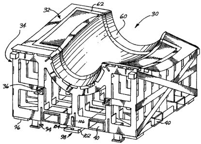
Fig. 1 is a perspective view of a dual purpose lay-up tool in accordance
with this invention;
Fig. 2 is a perspective view of a dual purpose lay-up tool indexed to the
base of a gantry mounted machine tool;
Fig. 3 is a sectional elevation of the tool face of the top plate of the tool
shown in Fig. 1 with elements of a part applied and showing outlines of the
cutter travel in trimming and other machining operations on the part while
still
mounted in the original position on the tool;
Fig.4 is a sectional elevation of a portion of the top plate of the tool shown
in Fig. 1, showning a caul sheet over the groove while the sacrificial
material in
the groove cures.;
Fig. 5 is an exploded perspective view showing an electrically heated caul
sheet over a tool according to this invention;
Fig. 6 is a perspective view of another form of a tool in accordance with
this invention, showing recesses in the top plate of the tool for various
cutouts;
Fig. 7 is a side elevation of a support structure for a tool like the tool
shown in Fig. 1;
Fig. 8 is a plan view of the tool support structure shown in Fig. 7;
Fig. 9 is a block diagram illustrating the process of translating digital date
from a digital part model to a form usable by the machine tool controller; and
Fig. 10 is a perspective view of a vacuum tool for cleaning dust from the
cells of honeycomb core elements machined on the tool shown in Fig. 1
DESCRIPTION OF THE PREFERRED EMBODIMENT
Turning to the drawings, wherein like reference numerals identify identical or
corresponding elements, and more particularly to Fig. 1 thereof, a dual
purpose
lay-up tool 30 is shown having a tool body such as a top plate 32 supported by
a
support structure 34. The top plate 32 is made of a material that is
compatible with
the constituent materials of the part, in terms of chemical and physical
properties.
4
CA 02201981 2005-03-08
For example, the top plate 32 preferably should have a coefficient of thermal
expansion that matches that of the constituent materials, particularly the
layer
placed in contact with the top plate (usually referred to as the "tool-side
skin"). If
the tool side skin is carbon fiber fabric preimpregnated with epoxy resin, a
commonly used material, the top plate 32 could itself be carbon fiber/epoxy
resin
composite material, or could be Invar 36, an alloy of nickel and iron having a
coefficient of thermal expansion closely matching that of carbon fibedepoxy
resin
composite material. Aluminum skins with aluminum honeycomb core typically use
aluminum tooling which closely match the CTE and are chemically compatible
with
the aluminum constituent materials.
The support structure 34 may be any suitable design, although the preferred
embodiment is the conventional "egg crate" design shown in Fig. t. Another
support structure which would be suitable would be one made with composite
tubes
attached together with fittings shown in U.S. Patent No. 5,100,255,
The support structure 34 has transport
accessories to facilitate movement of the tool 30 in the factory. The
transport
accessories in this preferred embodiment include lift rings 36 fastened hnro
each to
the front and bade sides of the support structure 34 for attachment of lifting
cables
which are engaged with the hook of an overhead crane for lifting and ferrying
the
2o tool 30 about in the factory. Another transport accessory which can be used
in
place of the lift rings 36, or preferably in addition to them, are fork lift
tubes 40 built
into the support structure 34 as shown in Fig. 1. The fork lift tubes 40
receive the
spaced tines of a fork lift by which the tool 30 may be lifted and moved about
the
factory.
Location and attachment devices are provided on the support structure 34
for accurately indexing and positioning the tool 30 on a base 42 of a machine
tool
such as a five-axis gantry machine tool 44 shown schematically in Fig. 2, and
for
fastening the support structure 34 to the machine tool bed d2 in the desired
position. The machine tool 44, under control by an machine tool controller 46,
3 o performs machining operations on the part laid up on the tool 30 after the
part is
cured. The location and attachment devices facilitate precise positioning of
the
tool 30 on the bed 42 so the machine toot controller can drive thp machine
tool to
the correct position for accurate machining of the part. The location devices
include set points, sine keys, and tool balls, the use of which are described
in
3 5 detail below. Use of these devices makes it possible to position the tool
30 on the
base 42 of the machine tool with extreme accuracy and to check that position
and
22019 1
adjust the machine program to conform to the actual position of the top plate
34 of
the tool 30, thereby facilitating accuracy in the subsequent machining
operations,
since the position of the tool 30 and the part laid-up thereon are known
accurately.
The attachment devices by which the tool 30 is secured to the machine
tool bed 42 may be any conventional devices known in the art for fastening a
workpiece to the bed of a machine tool. In this embodiment, the attachment
devices are conventional toe clamps, the design of which is known to those
skilled in the art.
The top plate 32 has an upper upwardly facing surface 60 on which the
1 o constituent elements of the part are laid-up. The upper surface 60 is
configured
to a desired shape of one surface of the part to be made on the tool. Upwardly
opening recesses are machined into the upper surface 60 of the top plate 32 at
positions corresponding to locations on the part that machining operations
will
be required later in the manufacturing process. The recesses include a
15 peripheral groove 62, located on the top plate 32 where the peripheral edge
of
the part will be cut, and a cylindrical well 63 located on the top plate 32
where
holes will be drilled through the part. Other continuous grooves are located
within the groove 62 where openings are to be cut out of the part. Some of the
various shapes of recesses are illustrated in Fig. 6. The recesses receive a
2 o sacrificial material 64 on which the constituent materials can be laid up
on the
top plate 32 flush with the upper surface 60.
The groove 62 is preferably dovetailed in cross-section as shown in Fig. 3
which assists in retaining the sacrificial foam material in the groove until
it is
removed. After curing, the foam material has a strength of about 500 PSI which
is
25 sufficiently strong to provide a supporting surface that holds the tool-
side plies flush
with the surface of the tool top plate 32 under normal circumstances. However,
if
greater strength is desired, one or more plies of graphite/epoxy prepreg tape
may
be added in the groove 62 over the foam material 64 to provide a more rigid
surface
that is capable, when cured, of distributing the load over a larger surface
and
30 thereby carrying a greater load. To facilitate removal of the foam material
64 from
the groove 62 after removal of the part, a separate strip of resin-impregnated
fabric
may be inserted into the groove 62 prior to applying the foam material
therei~.
The groove 62 extends completely around the central portion of the facing
surface 60 of the top plate 32 on which the constituent elements of the part
are to be
35 laid up, in an area of the surface where the net edge trim will be located.
Other
recesses are located in areas on the tool where holes are to be drilled
through the
6
CA 02201981 2005-03-08
part or where other machining through the part is required. The outer
peripheral
groove is a "continuous" groove in the sense that it completely encircles the
area on
which the part is laid up. However, there may be particular part designs that
require
a break or a gap in the groove, hence the tent "substantially continuous"
groove.
Preferably, the groove is just deep enough to enable a mill cutter 68 to
extend below
the Lacing surface 60 during its cutting pass so that its peripheral cutting
teeth can
engage and cut the full thickness of the peripheral edge of the part. The
depth of
the groove 62 in this embodiment is about 0.050", although it could be made
deeper
if the machine tool on which the cutter 68 is mounted cannot be programmed to
1o follow the contour of the top place 32 with the necessary precision.
The width of the groove 62 is selected to accommodate the diameter of
the cutter 68 plus the necessary tolerance in the path of travel of the cutter
68 in the
machine toot 44, An additional width of groove 62 is also provided on both
sides of
the kerf cut by the cutter 68 for holding the tool-side surface of the laid-up
maferials
bonded to the sacrificial material 64 to ensure that the part does not shift
during the
cutting operation but remains securely fixed in place on the top plate 32
until the
cutting operation is completed and the part is ready to be removed from the
tool 30.
The sacrifiaal material 64 can be any suitable material that can be
conveniently
applied to fill the groove 62 and has sufficient strength, temperature
resistance and
other properties to support the constituent materials during the
bonding/curing
operation. The preferred material used in this embodiment is B.F. Goodrich
#PL657
heat expandable self-skinning foam. It is applied as a bead or a cut strip in
the groove
62 and covered with a smooth molded caul sheet 70, as shown in Fig. 4. The
Gaul
sheet 70 is preferably a graphitelepoxy resin construction molded directly on
the top
~ surface of the top plate 32 before the groove 62 and other recesses are
machined
therein, and is cured thereon by heating to cure temperature for the cure
cycle while
covered with an evacuated vacuum bag 71. Vacuum tracks 73 may be molded into
the
underside of the Gaul sheet 70 by laying a bead of sealing tape, normally used
to seal
the edges of the vacuum bag 71 to the tool, along both sides of the path on
which the
3 o groove 62 wilt be machined in the top plate surface 60. The graphite/epoxy
sheets of
which the Gaul sheet is made are laid on the toot surface 60 over the beads of
tape
and cure in that shave to form the vacuum tracks 73. The sacrificial material
64 i~
expanded and cured in the groove by covering the groove 62 with the Gaul sheet
70
and a vacuum bag, and sealing the edges of the vacuum bag to the facing
surface 60
3 ~ of the top plate 32 with putty-like sealing tape 75 known in the art for
this purpose.
The vacuum bag is evacuated to a vacuum of about 10 inches of mercury and
vacuum
CA 02201981 2005-03-08
is applied in the vacuum tracks 73 to help hold the caut sheet down against
the top
surface 60 of the tool over the groove 62 while the foam expands against the
underside of the Gaul sheet over the groove 62 and then cures in the expanded
condition. To expand and cure the foam, the tool 30 is place in an oven or
autoclave
and heated to a temperature spedfied by the supplier of the foam material,
which is
about of between 260° for about 90 minutes for the B.F. Goodrich
#Pl.657 material.
A preferred technique for curing the foam 64 uses an electrically heated
Gaul sheet 72, shown in Fig. 5. The Gaul sheet 72 has an electrical heat tape
74
fastened to the top surface 76 of the Gaul sheet 72 in the region over the
groove
62, or embedded therein when the caul sheet 72 is made. An insulating blanket
77, shown partially in phantom lines in Fig. 5, can be Laid over the top of
the Gaul
sheet 72 to reduce the heat toss to the ambient air and lower the electrical
power
requirements to maintain an elevated temperature of the foam 64 while it
cures.
Temperature sensors 78 adjacent the heat tape produce signals that are
transmitted over conductors 79 to a controller 80 which monitors the
temperature
of the Gaul sheet 72 and adjusts the electrical power from a power source 52
delivered to the heat tape 74 to maintain the temperature at the desired cure
temperature of the foam 64 in the groove 62. The electrically heated Gaul
sheet
72 eliminates the need to occupy an expensive oven during the foam cure cycle,
thereby reducing the cost of the manufacturing process. _
After the foam 64 has cured, the vacuum bag 71 and caul sheet 70 or 72 is
removed and a release coating is applied to the tool face 60, on both sides of
the
groove 62, but is not applied to the sacrificial foam material 64 in the
groove 62.
The release coating ensures that the part will not adhere to the tool face
when the
~~ .. 25 time comes to remove it from the tool 30. The plies of the tool-side
skin 85 of the
part are applied to the tool face 60, overlapping the groove 62 and, as shown
in
Fig. 3, extending a short distance beyond the groove to provide an excess or
selvage. If the pan is a honeycomb core sandwich part, honeycomb core
elements 84 are fit in place on top of the tool-side plies with an adhesive
3 o expanding foam between the elements 84. Conveniently, the same expanding
foam material 64 used in the groove 62 may be used to bond the honeycomb
elements 84 together. .
A breather strip 87 is laid adjacent the tool-side plies 85 and the vacuum bag
71 is laid over the tool-side skin plies 85 and other components, such as the
35 honeycomb core elements 84. The peripheral edge of the vacuum bag 71 is
sealed
to the tool face around the outside of the groove 62 with sealing tape 75 or
the like,
8
221981
as known in the art. The space under the vacuum bag 71 and inside the
periphery
of the sealing putty is evacuated by a vacuum pump 86 communicating through a
vacuum line 88 with a vacuum port 90 in the tool adjacent the groove 62.
Conveniently, a check valve (not shown) in the vacuum port holds the vacuum
while
the tool 30 is transferred into an autoclave (not shown). In the autoclave,
the
vacuum port 90 is reconnected to the source 86 of vacuum and the autoclave is
pressurized and heated, causing the preimpregnated resin in the plies to flow
and
then cure while any outgassing from the curing resin is evacuated through the
vacuum line 88.
1o After the resin in the plies and components is cured, the temperature and
pressure in the autoclave is reduced to RTP and the tool 30 is transported to
the
machine tool bed 42. Retractable feet 94 on the support structure 34 of the
tool
30 are retracted to engage a datum surface 96 on the underside of the support
structure 34 with the machine tool bed 42. This establishes the vertical
position
of the facing surface 60 of the tool 30 from the machine bed 42, which is a
distance "known" to the machine program that controls the movement of the
gantry mounted machine tool 44. The retractable feet 94 are kept extended at
all other times, that is, during storage and movement of the tool 30 and
during
lay-up of the skin materials and constituent materials on the tool 30 to
protect
the accurately ground datum surface 96 from nicks or other damage that could
affect the distance between the datum 96 and the top surface 60 of the top
plate
32.
The position and orientation of the tool 30 on the machine bed 42 are
established by location devices, including a set point 98 and a sine key 100,
shown
in Figs. 7 and 8. The set point 98 includes a plate 102, fixed rigidly to the
underside of the support structure 34 of the tool 30 by welding or the like,
and an
accurately drilled and lapped vertical hole 104 in the plate 102. A precision
ground
pin 106, typically 2" in diameter, fits with a close sliding fit in the hole
104 and into
a selected one of numerous identically sized holes 108 in the machine bed 42,
shown in Fig. 2. The sine key 100, also shown in Figs. 7 and 8, includes a
plate
110 fixed, like the plate 102, to the underside of the support structure 34. A
smaller vertical hole 112 is accurately drilled and lapped in the plate 110
and
receives, also with a close sliding fit, an accurately ground pin 114,
typically 13/16"
diameter, that extends down beyond the plate 110 and fits into the same T-slot
116
in the machine tool base 42 in which the hole 108 is centered. When the pins
106
and 114 are in place in the plates 102 and 110, extending down into the hole
108
9
2_2~~1 X81
and the slot 116, the position of the tool 30 is uniquely positioned on the
machine
tool base 42. Its position can be input to the machine tool control program by
identifying the slot 116 and the hole 108 in which the pins are positioned.
That
information, together with a tool configuration data set and part
configuration data
set input into the machine tool controller 46, provides sufficient information
to
enable the machine tool controller to guide the machine tool to perform the
required cutting operations.
Turning now to Fig. 9, a process is illustrated schematically for transforming
digital part data into machine instructions that can be understood and used by
the
1o controller of the machine tool 44 to enable it to perform the desired
machining
operations on the part such as edge routing and hole drilling. A digital part
model
120 resident on a master computer 122 is provided to an NC machine programmer
who produces a program 124 using the part model 120. The program contains
information such as cutter type, spindle speeds, cutter feed speeds, depth of
cut,
number of passes and the path to be traversed by the cutter. The NC machine
program is processed through a post processor 126 to produce a program in a
format and medium that can be read by the machine tool controller 46. That
program is logged into a data base management system for storage and retrieval
when needed. The program is retrieved by the machine tool operator when he is
ready to make the part. He loads it into the machine tool controller and runs
the
program to perform the cutting operations on the part after it is properly
mounted
on the machine tool base 42 and probed to confirm its position.
Some parts require that separate core assemblies be made apart from the
tool-side skin and then be mated in one operation to the tool-side skin and
the
bag-side skin and co-cured together. For such parts, a single ply of graphite
epoxy is laid on the surface 60 of the tool and the elements of honeycomb core
are laid atop the tool-side ply. Strips of foam material such as the B.F.
Goodrich
#PL657 material are inserted between the foam core elements. A vacuum bag is
laid over the assembly and evacuated with a vacuum pump. The tool is put in an
3 o autoclave and the temperature and pressure are elevated for the cure
cycle. In
this version of the process, it may be unnecessary to separately cure the foam
in
the groove 62 using a caul sheet because the honeycomb core elements lies
over the groove and spans the groove, providing support to prevent the vacuum
bag from dimpling the foam in the groove 62 before it can cure. After the core
element has cured, the tool is taken to the machine tool and mounted on the
machine tool bed 42 and indexed in place. The core element is machined to
CA 02201981 2005-03-08
produce the sculpted shape desired for the part in which it is to used, and
the
periphery of the core element is cut following the peripheral groove 62 to
free
the core element from the tool. The sculpted and machined core element is
removed and mounted on a tool-side skin in the same or another tool. A bag
side skin is applied over the core element and a vacuum bag is laid over and
seated to the toot. The vacuum bag is evacuated and the tool is put in an
autoclave for co-curing both skins simultaneously.
Machine the core element 84 to produce the sculpted profile desired for
the part is an efficient and accurate technique for producing the desired
shape of
1 o the core element. However, removing dust and debris from the core cells
after
machining has proven difficult, espeaally when the part remains affixed to the
tool until the bag-side skin is cured. To facilitate removal of dust and
debris from
the core cells, a vacuum tool 130, shown in Fg. i 0, is slip over the top
surtace
of the core element. The vacuum tool has a hood 132 having a fitting 134 to
i5 which a vacuum hose 136 is attached. A pipe 138 is mounted in opposite
sides
of the hood 132 transverse across its opening. The pipe has a cow of small
holes 140 oriented toward the opening of the hood and has a quick disconnect
coupling 142 at its end for attachment to an air pressure hose 144.
In operation, the vacuum tool is connected to a vacuum hose 136 from a
20 source of vacuum, such as a shop vacuum cleaner, and an air hose 144 is
connected to the coupling 142. The hood is placed with its opening on the
surface of the honeycomb core and the air blowing through the row of holes 140
blows the dust out of the honeycomb cells and the vacuum dusty air is
withdrawn
from the hood 132 through the vacuum hose 136. The rate of air blown through
2 5 the holes 140 is less that the rate of air sucked out of the vacuum hood
132 by
t+~e vacuum source, so no dust is blown out of the hood 132. A set of shallow
notches 146 along the leading edge of the hood 132 allows air to be sucked
into the
hood and prevents a vacuum condition from building up inside the hood, which
could make it difficult to move the hood about over the surface at the core
3 o element 84.
Thus, the invention meets the objects noted above by providing a method
and apparatus for laying-up and curing/bonding the parts on a lay-up tool, and
providing the means for sculpting honeycomb core and trimming and drilling the
part while it is still on the original tool and still in the original
position. AN the
35 registry problems in the prior art process and apparatus are removed by
this
invention, resulting in substantially improved manufacturing conformance to
11
22019 1
specified tolerances, and the cost of building, maintaining and storing the
tooling is
reduced significantly. The improved capability of small tolerance
manufacturing
makes possible, for the first time, use of modern manufacturing techniques
with
these large laid-up parts, such as statistical tolerancing and determinant
assembly,
thereby further improving the quality and reducing the cost of the assemblies
in
which the parts are used.
Obviously, numerous modifications and variations of this preferred
embodiment will occur to those skilled in the art in light of this disclosure.
Accordingly, it is expressly to be understood that these modifications and
variation, and the equivalents thereof, shall be considered to be within the
spirit
and scope of the invention as defined in the following claims, wherein I
claim:
12