Note: Descriptions are shown in the official language in which they were submitted.
CA 02202143 1997-04-08
WO 96/12857 PCT/SE95/01206
PROCESS FOR THE PRODUCTION OF A FLOOR STRIP
The present invention relates to a process for the production of a floor strip
such
as a dilatation profile, a transition profile or a finishing profile.
It is previously known to produce floor strips such as metal strips, wood
veneer
coated strips and strips of homogeneous wood.
There is a strong desire to bring about a floor strip with the same pattern as
on a
floor of thermosetting laminate. During the last years these floors have
become
very usual. For instance they are made with wood pattern, marble pattern and
phantasy pattern. Possibi_y you can use a homogeneous wood strip or a wood
vene-
er coated strip for a few of the wood patterned floors. Previously known
strips do
not go well together with all the other floor patterns.
In addition the purpose of the present invention is to provide a floor strip
with
improved abrasion resistance.
According to the present invention it has quite surprisingly been possible to
meet
the above needs and bring about a process for the production of floor strips
such
as a dilatation profile, a transition profile or a finishing profile. The
process comp-
rises glueing, preferably under heat and pressure a thin decorative
thermosetting
laminate of postforming quality having an abrasion resistance measured as IP-
va-
lue >3000 revolutions, preferably >6000 revolutions, on a longitudinal
carrier,
which carrier preferably consists of a fibre board or a particle board with a
rectan-
gular cross-section and at least two opposite rounded-off edges. The
postforming
laminate is glued in one piece on the upper side and two long sides of the
carrier
via the rounded-off edges, whereupon one or more floor profiles having the
same
or different cross-section is machined from the laminate coated carrier.
According to one embodiment the carrier can be provided with a rectangular
cross-section with three rounded-off edges.
One great advantage of the process for the production according to the
invention
is that it is very rational. From the same body, the laminate clad carrier,
several
profiles with varying shape can be machined. Usually a milling machine is used
for
machining the different kinds of profiles from the laminate coated carrier.
Preferably the carrier is water resistant. At a preferred embodiment the
carrier
consists of a high density fibre board made of fine fibres.
CA 02202143 1997-04-08
WO 96/12857 2 PCTISE95/01206
At a preferred embodiment the postforming laminate is glued in one piece on
three
of the four longitudinal se.des of the carrier, preferably on the upper side
and two
long sides via the rounded-off edges. Advantageously, a heat and moisture resi-
stant glue is used at the glueing. Preferably the glueing is carried out under
heat
and pressure. For instance the pressure can be regulated by means of rollers
which
press the laminate against the carrier. The temperature can for instance be
regula- .,
ted with heating nozzles which can give an even current of warm air.
At another embodiment the carrier can be provided with a rectangular cross-sec-
tion and three rounded-off edges. The postforming laminate is then glued in
one
piece on all four sides of the carrier via the rounded-off edges.
Suitably the postforming laminate consists of at least one monochromatic or
pat-
terned paper sheet impregnated with a thermosetting resin, preferably melamine-
formaldehyde resin and preferably one or more sheets for instance of
parchment,
vulcanized fibres or glass fibres. The last mentioned sheets are preferably
not imp-
regnated with any thermosetting resin, but the thermosetting resin from the
sheets
situated above will enter these sheets at the laminating step, where all
sheets are
bonded together.
Generally the term postforming laminate means a laminate which is so flexible
that
it can be formed at least to a certain extent after the production thereof.
Ordinary
qualities of thermosetting decorative laminates are rather brittle and cannot
be re-
garded as postforming laminates.
Usually the postforming laminate includes at least one uppermost transparent
pa-
per sheet made of a-cellulose and impregnated with a thermosetting resin,
prefe-
rably melamine-formaldehyde resin. This so-called overlay is intended to
protect
an underlying decor sheet from abrasion.
Often at least one of the paper sheets of the postforming laminate impregnated
with thermosetting resin, preferably the uppermost one is coated with hard
partic-
les for instance silica, aluminium oxide and/or silicon carbide with an
average par-
ticle size of about 1-80 Vim, preferably about S'-60 ~m evenly distributed
over the
surface of the paper sheet.
In a preferred embodiment the hard particles are applied on the resin
impregnated
paper surface before the resin has been dried.
The hard particles improve the abrasion resistance of the laminate. Hard
particles
are used in the same way at the production of laminates which are subject to a
hard wear such as flooring laminates.
CA 02202143 1997-04-08
WO 96/12857 3 PCT/SE95/01206
The abrasion resistance of the postforming laminates are tested according to
the
European standard EN 438-2/6:1991. According to this standard the abrasion of
the decor sheet of the finished laminate to the so-called IP-point (initial
point) is
measured, where the starting abrasion takes place.
The IP-value suitably lies within the interval 3000-20000, preferably 3000-
10000
revolutions.
Thus, the manufacturing process according to the invention makes it possible
to
produce laminate clad profiles with the same surface pattern and about the
same
abrasion resistance as the laminate floorings they are intended to go together
with.
Of course the pattern of the profiles can also be adapted to other flooring
materi-
als than laminate floorings, such as parquette floorings and soft plastic
floorings.
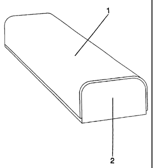
The present invention will be explained further in connection with the
embodiment
example below and the enclosed figures of which figure 1 shows a postforming
la-
minate 1 glued to a longitudinal carrier 2. Figure 2 shows a dilatation
profile 3
with a postforming laminate 1 glued thereto, while figure 3 illustrates a
finishing
profile 4 with a postforming laminate 1 glued thereto. Finally figure 4 shows
a
transition profile 5 with a postforming laminate 1 glued thereto.
On the figures the thickness of the postforming laminate 1 has been magnified
as
compared to the size of the carrier 2 and the profiles 3-5 respectively to
better il-
lustrate that a postforming laminate 1 is glued to the carrier 2 and the
profiles 3-5
respectively.
Of course the figures 1-4 only show one embodiment of the carrier 2 and the
pro-
files 3-5 respectively which can be produced according to the invention.
Various
other designs are possible.
Example
A roll of transparent so-called overlay paper of a-cellulose with a surface
weight
of 25 g/m2 was impregnated with an aqueous solution of melamine-formaldehyde
resin to a resin content of 70 percent by weight calculated on dry impregnated
pa-
per. Immediately after the impregnation, aluminium oxide particles with an
avera-
ge particle size of 50 ~m were applied to the upper side of the paper in an
amount
of 7 g/m2 by means of a doctor-roll placed above the paper web.
Thus, the hard aluminium particles were applied in the melamine-formaldehyde
re-
sin which had not been dried yet.
CA 02202143 1997-04-08
WO 96/12857 4 PCT/SE95/01206
The impregnated paper web was then fed continuously into a heating oven, where
the solvent was evaporatcd. At the same time the resin was partially cured to
so-
called B-stage. Thereby the aluminium oxide particles were enclosed in the
resin
layer and arcordingly concentrated to the surface of the product obtained
which is
usually called prepreg. The prepreg web obtained was then rolled again.
A roll of conventional nontransparent so-called decor paper with a decor
pattern
printed thereon and having a surface weight of 80 g/m2 was treated in the same
way as the overlay paper except for the fact that no aluminium oxide particles
were applied and that the resin content was SO percent by weight calculated on
dry
impregnated paper.
A roll of unimpregnated parchment with a surface weight of 120 g/m2 was used
at
the production of the postforming laminate.
The two prepreg webs impregnated with melamine-formaldehyde resin and the
unimpregnated parchment web were pressed between two press bands of a conti-
nuous laminating press to a decorative postforming laminate.
At the pressing a prepreg web of a-cellulose was placed on top with the side
with
the hard particles directed upwards. Underneath followed a prepreg web of
decor
paper and at the bottom a web of parchment. The prepreg webs and the parchment
web were pressed together at a pressure of 35 kp/cmz and at a temperature of
170°C.
The decorative postforming laminate obtained was cut with roller knives to
strips
of suitable length and width.
A longitudinal carrier 2 with a rectangular cross-section and two opposite
roun-
ded-off edges according to figure 1 was machined from a fibre board by means
of
a milling machine. The fibre board was a water resistant board of so-called
MDF-
quality (medium density fibre board quality) of high density made of finely
divided
fibres.
A strip of postforming laminate 1 was glued under heat and pressure to the
long-
itudinal carrier 2 with a heat and moisture resistant glue. The pressure was
regula-
ted with rolls which pressed the laminate against the carrier and the
temperature
was regulated with heating nozzles which blew an even current of warm air.
A dilation profile 3 according to figure 2 was machined from the laminate clad
carrier by milling.
CA 02202143 1997-04-08
WO 96/12857 5 PCT/SE95/01206
Instead two finishing profiles 4 according to figure 3 or one transition
profile 5
according to figure 4 can be produced from the same carrier. This results in a
ra-
tional and cost-saving production.
The abrasion resistance of the postforming laminate obtained was measured.
Then
a value for the IP-point amounting to 7000 revolutions was obtained.
The present invention is not limited to the embodiments disclosed, since these
can
be modified in different ways within the scope of the present invention.