Language selection

Search

Patent 2202454 Summary

Third-party information liability

Some of the information on this Web page has been provided by external sources. The Government of Canada is not responsible for the accuracy, reliability or currency of the information supplied by external sources. Users wishing to rely upon this information should consult directly with the source of the information. Content provided by external sources is not subject to official languages, privacy and accessibility requirements.

Claims and Abstract availability

Any discrepancies in the text and image of the Claims and Abstract are due to differing posting times. Text of the Claims and Abstract are posted:

  • At the time the application is open to public inspection;
  • At the time of issue of the patent (grant).
(12) Patent Application: (11) CA 2202454
(54) English Title: HOCKEY STICK
(54) French Title: BATON DE HOCKEY
Status: Dead
Bibliographic Data
(51) International Patent Classification (IPC):
  • A63B 59/70 (2015.01)
(72) Inventors :
  • TSAI, SON-KUNG (Taiwan, Province of China)
(73) Owners :
  • TSAI, SON-KUNG (Taiwan, Province of China)
(71) Applicants :
  • TSAI, SON-KUNG (Taiwan, Province of China)
(74) Agent: OSLER, HOSKIN & HARCOURT LLP
(74) Associate agent:
(45) Issued:
(22) Filed Date: 1997-04-11
(41) Open to Public Inspection: 1998-10-11
Availability of licence: N/A
(25) Language of filing: English

Patent Cooperation Treaty (PCT): No

(30) Application Priority Data: None

Abstracts

English Abstract


A hockey stick consists of a shaft and a blade fastened with one end ofthe longitudinal axis of the shaft for hitting the puck. The shaft is
provided at one end thereof with a connection portion while the blade
has a neck provided with a connection slot which is engaged securely
with the connection portion of the shaft. The connection portion is
reinforced by at least one reinforcing member for averting the crack or
severance of the junction between the connection portion and the shaft.


French Abstract

Cette invention concerne un bâton de hockey composé d'un manche et d'une lame solidaire d'une des extrémités dudit manche et servant à la frappe d'une rondelle. Le manche comporte à une extrémité un embout de raccordement tandis que la lame comporte une partie coudée à fente qui se glisse sur cet embout pour former un assemblage solide. L'embout de raccordement est renforcé à l'aide d'un moins un élément de renfort destiné à empêcher les fissures ou la séparation à la jonction entre l'embout de raccordement et le manche.

Claims

Note: Claims are shown in the official language in which they were submitted.


THE EMBODIMENTS OF THE INVENTION IN WHICH AN EXCLUSIVE
PROPERTY OR PRIVILEGE IS CLAIMED ARE DEFINED AS FOLLOWS:

1. A hockey stick comprising:

a shaft having a rod-shaped body and a connection portion
fastened at one end of a longitudinal axis of said body, said connection
portion having a cross-sectional area smaller than a cross-sectional area
of said body;

a blade having a neck which is provided with a planar top with a
connection slot extending from said planar top into an interior of said
neck, said neck of said blade being fastened with said body of said shaft
such that said connection slot is securely engaged with said connection
portion; and

at least one reinforcing member fastened intimately with said
connection portion of said shaft such that said reinforcing member
extends from said connection portion toward said body of said shaft.

2. The hockey stick as defined in claim 1, wherein said shaft is
made of a wooden material.

3. The hockey stick as defined in claim 1, wherein said reinforcing
member is made of a metal material.

4. The hockey stick as defined in claim 1, wherein said reinforcing
member is made of a fiber-reinforced plastic material.

5. The hockey stick as defined in claim 1, wherein said reinforcing


member is extended to reach another end of the longitudinal axis of said
body.

6. The hockey stick as defined in claim 1, wherein said connection
portion of said shaft has a rectangular cross section; and wherein said
reinforcing member has a width equal to the length of long sides of said
rectangular cross section of said connection portion.

7. The hockey stick as defined in claim 5, wherein said connection
portion of said shaft has a rectangular cross section; and wherein said
reinforcing member has a width equal to the length of long sides of said
rectangular cross section of said connection portion.

8. A hockey stick comprising:

a wooden shaft having a rod-shaped body and a connection
portion fastened at one end of a longitudinal axis of said body, said
connection portion having a rectangular cross-sectional area smaller than
a cross-sectional area of said body;

a blade having a neck which is provided with a planar top with
a connection slot extending from said planar top into an interior of said
neck, said neck of said blade being fastened with said body of said shaft
such that said connection slot is securely engaged with said connection
portion; and

two reinforcing members greater in strength than said wooden
shaft and having a width equal to the length of long sides of a
rectangular cross section of said connection portion, said two reinforcing


members being intimately fastened with two outer sides of said
connection portion such that said two reinforcing members extend
towards said body for a predetermined length.


Description

Note: Descriptions are shown in the official language in which they were submitted.


CA 022024~4 1997-04-11


HOCKEY STICK


FIELD OF THE INVENTION

The present invention relates generally to a hockey, and more
particularly to a hockey stick.


BACKGROUND OF THE INVENTION

The conventional hockey stick is generally composed of a wooden
shaft and a wooden or plastic blade fastened at one end of the shaft for
hitting a puck. The fastening ends of the shaft and the blade are similar
in cross-sectional area. The fastening end of the shaft is provided with a
connection portion while the fastening end of the blade is provided with
a connection slot which is engaged securely with the connection portion
of the shaft.

Such a conventional hockey stick as described above is defective
in design in that the stress is bound to concentrate on the fastening ends
of the shaft and the blade at the time when the blade strikes violently the
puck. As a result of the stress concentration, the connection portion of

CA 022024~4 1997-04-11


the shaft is rather vulnerable to crack or severance.


SUMMARY OF THE INVENTION

The primary objective of the present invention is to provide an
improved hockey stick free from the shortcoming of the conventional
hockey stick described above.

In keeping with the principle of the present invention, the
foregoing objective of the present invention is attained by a hockey stick,
which consists of a shaft and a blade fastened with one end of the shaft
for hitting the puck. The shaft is provided at one end thereof with a
connection portion while the blade has a neck provided with a
connection slot which is engaged securely with the connection portion of
the shaft. The connection portion of the shaft is provided with a
reinforcing member for averting the crack or severance of the junction
between the connection portion and the shaft.

The foregoing objective, features, functions and advantages of the
present invention will be more readily understood upon a thoughtful
deliberation of the following detailed description of the embodiments of
the present invention in conjunction with the accompanying drawings.


BRIEF DESCRIPTION OF THE DRAWINGS

CA 022024~4 1997-04-11


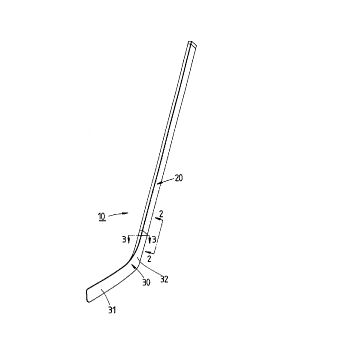
FIG. 1 shows a perspective view of a first preferred embodiment of
the present invention.

FIG. 2 shows a sectional view of a portion taken along the
direction of a line 2-2 as shown in FIG. 1.

FIG. 3 shows a sectional view of a portion taken along the
direction indicated by a line 3-3 as shown in FIG. 1.

FIG. 4 shows a sectional view of a second preferred embodiment
of the present invention, with the sectional view being taken along the
direction similar to that of FIG. 2.

FIG. 5 shows a sectional view of a third preferred embodiment of
the present invention.


DETAIl,Fl) DESCRIPTION OF THE INVENTION

As shown in FIGS. 1-3, a hockey stick 10 of the first preferred
embodiment of the present invention is composed of a shaft 20, a blade
30 fastened with one end of the shaft 20, and a reinforcing member 40
for enhancing the structural strength of the fastening portion located
between the shaft 20 and the blade 30.

The wooden shaft 20 has an elongate body 21, a connection
portion 22, a ring-shaped step face 23, and a slit 24. The body 21 has a
rectangular cross section. The connection portion 22 is an extension of


CA 022024~4 1997-04-11


the body 21. The step face 23 is located between the body 21 and the
connection portion 22. The slit 24 is located such that it extends from the
center of the bottom of the connection portion 22 to reach the portion
beyond the step face 23.

The blade 30 is made of a wooden or plastic material and is
composed of a puck-hitting face 31 and a neck 32 extending from the
puck-hitting face 31. The neck 32 is corresponding in cross section to
the body 21 of the shaft 20 and is provided at the free end thereof with a
connection planar surface 33 having a connection slot 34 extending into
the interior of the neck 32. The connection slot 34 is intended to engage
the connection portion 22 of the shaft 20.

The reinforcing member 40 is made of a metal or fiber-reinforced
plastic material and is received in the slit 24 of the shaft 20. The
reinforcing member 40 serves to reinforce the connection portion 22
which is engaged with the connection slot 34 of the blade 30.

As shown in FIG. 4, the connection portion 22 of the shaft 20 is
provided with two identical reinforcing members 40' extending into the
body 21 of the shaft 20.

As shown in FIG. 5, a hockey stick 50 of another embodiment of
the present invention is composed of a shaft 60 which is formed of two
wooden strips 62 and 64, and an elongated reinforcing member 70. The
strips 62 and 64 are rectangular in cross section. The reinforcing member
70 is made of a fiber-reinforced plastic material. The width of the
reinforcing member 70 is preferably corresponding to the length of the
rectangular cross section of the strips 62 and 64. The reinforcing member


CA 022024~4 1997-04-11


70 is sandwiched between the strips 62 and 64 such that the reinforcing
member 70 extends from the tip of the body 66 to the end of the
connection portion 68.

Representative Drawing
A single figure which represents the drawing illustrating the invention.
Administrative Status

For a clearer understanding of the status of the application/patent presented on this page, the site Disclaimer , as well as the definitions for Patent , Administrative Status , Maintenance Fee  and Payment History  should be consulted.

Administrative Status

Title Date
Forecasted Issue Date Unavailable
(22) Filed 1997-04-11
(41) Open to Public Inspection 1998-10-11
Dead Application 2001-04-11

Abandonment History

Abandonment Date Reason Reinstatement Date
2000-04-11 FAILURE TO PAY APPLICATION MAINTENANCE FEE

Payment History

Fee Type Anniversary Year Due Date Amount Paid Paid Date
Application Fee $150.00 1997-04-11
Maintenance Fee - Application - New Act 2 1999-04-12 $50.00 1999-04-09
Owners on Record

Note: Records showing the ownership history in alphabetical order.

Current Owners on Record
TSAI, SON-KUNG
Past Owners on Record
None
Past Owners that do not appear in the "Owners on Record" listing will appear in other documentation within the application.
Documents

To view selected files, please enter reCAPTCHA code :


To view images, click a link in the Document Description column. To download the documents, select one or more checkboxes in the first column and then click the "Download Selected in PDF format (Zip Archive)" or the "Download Selected as Single PDF" button.

List of published and non-published patent-specific documents on the CPD .

If you have any difficulty accessing content, you can call the Client Service Centre at 1-866-997-1936 or send them an e-mail at CIPO Client Service Centre.


Document
Description 
Date
(yyyy-mm-dd) 
Number of pages   Size of Image (KB) 
Description 1997-04-11 5 134
Abstract 1997-04-11 1 16
Claims 1997-04-11 3 78
Drawings 1997-04-11 1 22
Cover Page 1998-10-15 1 31
Representative Drawing 1998-10-15 1 3
Fees 1999-04-09 1 57
Assignment 1997-04-11 2 92
Fees 2001-03-16 1 31