Note: Descriptions are shown in the official language in which they were submitted.
CA 02202536 2006-03-16
1
FLEXIBLE ELECTRICAL CONDUCTOR
Background Of Invention
The present invention relates to electricity supply apparatuses and more
particularly
relates to an electrical conductor for use with such apparatuses particularly
flexible conductive
tracks for use in walls, floors, skirting boards or ceilings.
Prior Art
In the past, flexible electric conductors have been known for use with
electrical
distribution systems and in particular, flexible conductive tracks.
One such conductor was disclosed in international application WO 93/ 03517
wherein there is disclosed an insulating housing able to travel around curves
and corners
without the need to provide corner junctions or adaptors.
The known electrical distribution systems including flexible conductive tracks
include a
plurality of longitudinally extending recesses which close when the flexible
conductive track is
bent.
The flexible conductor disclosed in the above PCT application comprises solid
copper
wire supporting a conductive blade which has a series of cut outs along its
length. It was found
that this track did not perform to expectation in that it was not wholly
conducive to bending
and in fact sometimes resulted in damage to the conductive elements. An
alternative electrical
conductor for use in a flexible conductive track was disclosed in a subsequent
application by
the same applicant as that for the above PCT international application. That
application, issued as
Australian Patent 655069, disclosed an elongate flexible conductor assembly
located in a
longitudinally extending slot in a housing for use in an electrical bus
distributor. The conductor
disclosed in that specification comprised a coiled hollow conductor located in
slots provided in the
elongate flexible insulated housing. In order to effect engagement between the
conductor and the
electrical plug, pins on the plug were adapted with connector sockets formed
by a bifurcated
member which upon engagement with the continuous conducting element spread
apart and engaged
the conductor on either side. In use, it is predictable that the electrical
contact between the connector
sockets and the conductor will sometimes be compromised as the sockets after
continued use begin
to loose their elastic memory upon which reliance was placed to effect proper
electrical connection.
A flexible electrically conductive track is discussed in Australian Patent
655069. The
elongated flexible electric conductor consists of a length of conductive wire
over which there is
placed prongs or arms. A plug having one or more tines engages the conductor
by having its tine
located between the lugs or arms. A cover strip is employed to enclose the
conductor,
however it has to be removed to provide access to the conductor thereby making
the strip
prone to be lost.
The above discussed electric conductor has the disadvantage that it is made of
several
components requiring assembly. This adds to the cost of manufacture.
SUBSTITUTE SHEET (RULE 26)
CA 02202536 1997-04-11
WO 96/12327 PCT/AU95/00675
2
Still further, the conductor is located within insulating material which is
then inserted
in an extrusion. The extrusion provides a cavity for the conductor and
insulating material and
provides a slot through which a plug is inserted to engage the conductor.
A disadvantage of the above discussed arrangement is that dust and water can
enter the
extrusion.
Summary of the Invention
There is disclosed herein an elongated flexible electric conductor of unitary
construction, said conductor comprising:
two longitudinally extending edge strips which are transversely opposed so
that a gap is
i o defined therebetween; and
a plurality of transverse rib elements extending between the strips, the
elements being
located at space locations along the conductor so that the elements are
spaced, with the
elements being resiliently deformable so that the strips are urged toward each
other.
There is further disclosed herein an electric duct assembly comprising:
an elongated housing generally enclosing a longitudinally extending hollow and
having
a longitudinally extending slot to provide access to the hollow;
an elongated insulated electrical conductor mounted within the hollow and
adapted to
be engaged at a selected position along the housing by an electrical connector
to receive
electric power from the conductor; and
displaceable cover means captively mounted with respect to the housing and
closing
said slot but displaceable therefrom to provide access to said connector.
There is still further disclosed herein an elongated insulating member for an
electric
conductor, said insulating member having longitudinally extending slot to
receive the
conductor, and at least resiliently deformable flange closing the slot but
being displaceable to
provide access to the conductor.
Brief Description of the Drawings
Preferred forms of the present invention will now be described by way of
example with
reference to the accompanying drawings wherein:
Figure 1: shows a perspective view of a continuous conductor according to a
preferred embodiment of the invention;
Figure 2: shows a cross sectional view of the continuous conductor of Figure 1
embedded in an insulating housing;
Figure 3: shows the conductor of Figure 2 with a pin of an electrical plus
inserted
therein;
Figure 4: shows another cross sectional view of the continuous conductor
wherein
a portion only of the conductor is embedded in an insulating housing;
Figure 5: shows a cross sectional view of a conductor having an alternative
configuration embedded in an insulating housing;
SUBSTITUTE SHEET (RULE 26)
CA 02202536 2006-03-16
3
Figt,tre 6: shows a cross section of a flexible electrical duct showing
typical
engagement between the pin of an electrical plug and a continuous conductor
according to one
embodiment of the invention;
Figure 7: shows a plan view of a continuous flexible conductor showing a
series of
ribs according to a preferred embodiment;
Figure 8: shows a cross sectional view of a flexible conductor according to an
alternative embodiment of the invention;
Figures 9a, 9b: show the ribs of a typical spine of the flexible electrical
conductor of
Figure 8 in the folded and unfolded configurations;
Figure 10 is a schematic perspective view of an electric duct;
Figure 11 is a schematic part sectioned end elevation of the duct of Figure 8;
Figure 12 is a schematic perspective view of a length of insulating material
employed
in the duct of Figure 10;
Figure 13 is a schematic side elevation of a connector which may be used with
the duct
of Figure 10;
Figure 14 is a schematic perspective view of an elongated flexible electric
conductor
and a surrounding insulation;
Figure 15 is a schematic sectioned end elevation of the conductor and
insulating
material of Figure 12;
Figure 16 is a schematic perspective view of a cover strip employed in the
duct of
Figure 10;
Figure 17 is a schematic end elevation of the cover of Figure 16;
Fisure 18 is a schematic end elevation of a duct housing adapted to receive
the
conductor and insulating material of Figure 14;
Figure 19 is a schematic end elevation of the duct of Figure 18;
Figure 20 is a schematic perspective view of the duct of Figure 18;
Figure 21 is a schematic perspective view of the conductor of Figure 14;
Figure 22 is a schematic end elevation of the conductor of Figure 21;
Figure 23 is a schematic side elevation of the conductor of Figure 21;
Figure 24 is a schematic end elevation of a further insulating member;
Figure 25 is a schematic end elevation of the insulating member of Figure 24,
inserted
in an elongated supporting housing;
Fieure 26 is a schematic end elevation of an electric conductor employed in
Figure 25; and
Figure 27 is a schematic perspective view of a further electric conductor.
Detailed Description of The Invention
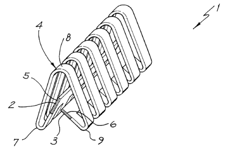
Referring to Figure 1 there is shown a conducting element 1 according to a
preferred
embodiment of the invention. In this embodiment the conductor has two spines
however, it
will be appreciated that the conductor can be formed from one spine wherein
the ribs each
have a free end. Element I comprises continuous spines 2 and 3 to which
attached to
SUBSTITUTE SHEET (RULE 26)
CA 02202536 1997-04-11
WO 96/12327 PCT/AU95/00675
4
secondarv conductive ribs 4. Preferably, the secondarv conductive rib 4 are
each inteQral with
spines 2 and 3. Each rib 4 has fixed ends 5 and 6 terminating at spines 2 and
3 respectively
and include first, second and third bends 7, 8 and 9. By introducing the
bends, end 5
terminates close to end 6 of rib 4 thereby forming a set of jaws which receive
a pin (see
Figure 3) from an electric plug. The jaws displace when the pin is inserted
therebetween
ensuring that ends 5 and 6 are urged into continuous electrical contact with
the pin.
Referring to Figure 2 there is shown a cross sectional view of the continuous
electrical
conductor of Figure 1 embedded in a plastics housing 10. Conductor 1 comprises
a series of
ribs integral with spines 2 and 3. In Figure 2 typical rib 4 comprises copper.
Rib 4 is
i o configured according to this embodiment by cold bending such that a series
of bends 7, 8 and
9 are introduced so that end 5 locates close to end 6 thereby forming the jaws
within which pin
19 (see Figure 3) penetrates to establish an electrical connection. Housing 10
comprises outer
casing 14 and inner core 15. Outer casing 14 is formed from a flexible but
firm plastics
material, whereas inner core 15 comprises a softer and more flexible plastics
material.
According to this embodiment, rib 4 is almost completely embedded in inner
core 15 save for
ends 5 and 6 which must be outside the housing 10 to enable electrical contact
between pin 19
inserted therein (see Figure 3) and ends 5 and 6. Housing 10 includes a
passage 16 into which
pin 19 penetrates to establish electrical contact with ends 5 and 6.
Figure 2 shows the configuration of the rib 4 and contour of inner core 15
prior to
insertion of the pin 19 to establish electrical contact. Before insertion of
the pin, ends 5 and 6
are almost perpendicular to each other, and are maintained in that attitude by
protrusions 17
and 18 of inner core 15. Although protrusions 17 and 18 provide some
resistance for ends 5
and 6, ends 5 and 6 rely primarily on the resilience in the flexible copper
material to be
restored to the rest configuration when pin 19 is released. When the pin is
inserted then
released, the elastic memory in the copper conductor performs a crucial role
in preserving the
integrity of the electrical contact. The movement of the copper is so minimal
when the pin is
inserted that it retains its elastic memory.
Referring to Figure 3 there is shown a cross sectional view of a the
conductive rib 4 of
Figure 2 this time with pin 19 of an electrical plug inserted therein.
Conductive rib 4 is shown
3o embedded in insulated housing 10 as described for Figure 2. When pin 19 is
inserted between
ends 5 and 6, ends 5 and 6 are urged against pin 19 due to the natural bias
towards the pin
created by bends 20 and 21, and/or upper apex respectively therebv ensurinQ
continuous
electrical contact between pin 19 and ends 5 and 6 respectively.
Referring to Figure 4 there is shown the rib 4, this time only partially
inserted in an
alternative housing 22. According to this embodiment housing 22 does not
include an inner
core analogous to inner core 15 shown in Fiaures 2 and 3. Rather, rib 4 is
disposed in clear
passage 23 with only bend 8 embedded in the plastics material of housing 22.
According to
this embodiment the integrity of the electrical connection between ends 5 and
6 is reliant on
the elastic memory in the copper and hence the resilience of the copper
material.
SUBSTITUTE SHEET (RULE 26)
CA 02202536 1997-04-11
WO 96/12327 PCT/AU95/00675
Referrina to Figttre 5 there is shown an alterative configuration of rib and
housing.
According to this embodiment, housing 24 includes rib 25 which includes a
substantially
circular body 26 which terminates at spines 27 and 28. As with the rib 4 in
Figure 4, rib 25 is
only partially embedded in housing 24 via sector 29. Electrical connection
between a pin (not
5 shown) and spines 27 and 28 is effected in a similar manner as that
described with reference to
Figure 3. The grooves 27a (see Figure 7) must end before returns 26a and 26b
of body 26
otherwise flexibility of the continuous conductor will be compromised.
Similarly for the ribs
of Figures 1 - 4. The grooves extend around and past the returns 26a and b, if
not flexibility
will be compromised.
Figure 6 shows a cross sectional view of a typical flexible skirting duct
assembly 30
incorporating continuous electrical conductors 31 and 32. Typically, dust
housing 33 is
mounted on a wall surface where power is required. Housing 33 includes plastic
housing 34
which receives and supports conductors 31 and 32. The arrangement shown in
Figure 6
incorporates the conductor and housing arrangement of Figure 5 previously
described. When
electrical contact is to be made between the electrical plug 35 and continuous
conductors 31
and 32 plug 35 is advanced towards opening 36 so that pins 37 and 38 are able
to penetrate the
opening. This can only be achieved when plug 35 is rotated so that pins 37 and
38 are parallel
to the longitudinal axis of opening 36. When the plug is inserted and once
pins 37 and 38 are
in alignment with openings 39 and 40 respectively, plug 35 is then rotated to
enable pins 37
2o and 38 to engage conductors 31 and 32 according to the manner previously
described.
Conductors 31 and 32 are configured so as to allow bending where the duct, for
instance, is required to travel around corners and curved surfaces and also to
enable tight
interfitting between pins 37 and 38 and the conductors thereby ensuring the
integrity of the
electrical connection.
Due to the separation between the conducting ribs, the duct in which the
electrical
conductor is located is able to be freely bent without risking breaking
electrical contact
between pin and the jaws of each rib. In the circumstance where heat is
induced in the
connection electrical contact is not dependent upon the insulating material of
the housing to
ensure electrical connection between the jaws. If the electrical connection
relies on the
3o integrity of the insulating material for contact and heat affects the
insulating material electrical
contact can very often be affected. AccordinQ to the present invention the
jaws of the
conductinQ elements are sufficiently biased towards the pin 19 to ensure that
electrical contact
is independent of the integrity of the insulating material.
Figure 7 shows a plan view of a flexible electrical conductor 45 according to
a
preferred embodiment. Conductor 45 includes a series of spaced apart ribs 46
which are
integral with spines 47 and 48.
According to an alternative embodiment of the invention there is provided a
flexible
electrical conductor comprising a rib and spine arranQement manufactured from
a non-
conductive material wherein the spine is contoured to receive a conductive
element such as a
SUBSTITUTE SHEET (RULE 26)
CA 02202536 1997-04-11
WO 96/12327 PCT/AU95/00675
6
copper wire or strip as a transporter of electrical current. Preferably, the
non-conductive
material is phosphorous bronze which has sufficient flexibility and
durability. Thus, the
manufacture of the spine and rib arrangement from a flexible material
satisfies the flexibility
requirement but may not satisfy the conductivity requirements. The latter is
provided by the
introduction of the copper strip or wire. The electric plug which is inserted
into the spine
makes contact with the copper wire to effect electrical connection. This
arrangement can result
in both reduced material costs and electrical resistance.
Referring to Figure 8 there is shown a cross sectional view of a flexible
conductor
according to an alternative embodiment of the invention. The flexible
conductor comprises a
i o spine 50 comprising ribs 51 and 52 which may be of equal or unequal length
and which
terminate in free ends 53 and 54 respectively. In Figure 8 the ribs 51 and 52
are shown as
having unequal length. One advantage of the ribs having unequal length is that
the spines may
pass each other when the flexible conductor is bent to travel around a comer
(see Figures 9a
and b below). The embodiment of spine 50 of Figure 8 is shown partially
embedded in flexible
PVC mould 55.
Referring to Figures 9a and b there is shown a typical spine 56 in isolation
from the
plastics mould. Figure 9a shows ribs 57 and 58 as they would normally be
disposed. Figure 9b
shows rib 57 urged substantially into alignment with rib 58. This occurs when
the flexible
conductor is bent around a corner and reduces the space taken by the ribs
resulting in
slimming at bends and corners. At the end of each of ribs 57 and 58 are copper
conductors 59
and 60 which contact a conducting pin of an electrical plug inserted into the
flexible
conductor.
In Figure 10 there is schematically depicted an electric duct 110 which
includes an
elongated housing 111 consisting of two sections 112 and 113. The elongated
sections 112
and 113 could be, for example, aluminium or plastics extrusions. The sections
111 and 112
cooperate to enclose a hollow within which there is located three elongated
flexible electric
conductors 114 located within an elongated flexible insulating member 115.
The sections 112 and 113 cooperate to define a slot 16 which is closed by a
cover
member 117.
In use of the above described duct 110, the duct 110 is used in conjunction
with a plug
or connector 118 (Figure 13) which includes three tines 119 each adapted to
selectivelv ensage
a respective one of the conductors 114. The connector 118 has a base 120 which
is inserted
through the slot 116 whereafter the connector 118 is rotated bringing the
tines 119 into contact
with the conductors 114.
The cover member 117 for example may be formed of expanded foam material and
may be transversely slotted or grooved.
When the connector 118 is inserted through the slot 116, the member 117 is
resiliently
deformed to provide access to the conductors 114. When the connector 118 is
removed, the
member 117 resumes its position closing the slot 116.
SUBSTITUTE SHEET (RULE 26)
CA 02202536 1997-04-11
WO 96/12327 PCT/AU95/00675
7
In Figure 11 there is schematically depicted an alternative extrusion 120 to
receive
three conductors 121 located within an elonaated insulating member 122.
The extrusion 120 has a lonaitudinallv extending end wall 123 from which there
extends two longitudinally extending flanges 124 and 125. The flange 124
terminates with a
longitudinally extending barb 126 while the flange 125 has a longitudinally
extending barb
127.
The insulating member 122 has longitudinally extending ridges 128 and 129
which
cooperate with the barbs 126 and 127 to retain the insulating member 122 and
therefore the
conductors 121 in position.
The end wall 123 is also provided with a longitudinally extending ridge 130
which
extends into a longitudinally extending valley formed in the insulating member
122.
The conductors 121 and insulating member 122 are flexible.
As best seen in Figures 21 to 23, the conductors each include two
longitudinally
extending edge strips 131 joined by transverse elements 132, with the elements
132 being
located at spaced locations along the conductor 121. The conductors 121 are
basically formed
of phosphorus bronze so as to be resilient while there is further provided
copper strips 133
extending along the strips 131. The strips 131 provide longitudinally
extending spines.
As best seen in Figure 22, the strips are spaced first in a first direction by
the distance
"A" and then by a second distance "B", which distances are perpendicular and
transverse the
lonaitudinal direction of extension of the conductor 121.
In Figures 14 and 15 there is schematically depicted an alternative
configuration of the
insulatina member 132. In this particular embodiment the insulating member 132
has a central
longitudinally extending slot 134 which would cooperate with a correspondingly
shaped barb
located on a wall of a surrounding extrusion.
For example, the insulating member 132 and conductors 121 as shown in Figures
14
and 15 may be incorporated in an extrusion 135 as shown in Figures 18 and 19.
The
extrusion 135 has a wall 136 from which there extends a barb 137 to engage
within the slot
134. In this embodiment, the extrusion 135 has a pair of spaced end walls 138
and 139
between which there extends closure members 140 and 141. Both members 140 and
141
ao would be pivotally attached to an associated one of the walls 138 and 139
and would be
movable to the position depicted in Figure 16 from the position depicted in
Figure 19. A lip
142 would aid in retaining them in the position depicted in Figure 18. The
closure members
140 and 141 would be provided in segments to permit a portion of the extrusion
135 to be
exposed to provide access for a connector to engaae the conductors 121. In
this embodiment
the extrusion 134 is adapted to be incorporated in a floor, such as a computer
floor.
In Figure 24, there is schematicallv depicted an elongated insulating member
150.
formed of flexible plastics material. Typically, the insulating member 150
would be extruded.
The insulated member 150 is intended for inclusion in an elongated support 151
which may be
an aluminium or plastics extrusion or similar type extrusion. The support 151
has an
SUBSTITUTE SHEET (RULE 26)
CA 02202536 1997-04-11
WO 96/12327 PCT/AU95/00675
8
"L-shape" flange 152 including a first flange portion 153 extending generallv
normal to the
base 154. Depending from the portion 153 is a further portion 155. The
portions 153 and
155 co-operate with the base 154 to define an elongated slot 156 within which
the insulating
member 150 is located and held. The base 154 has a longitudinally extending
rib 157 which
inhibits removal of the insulating member 150 from within the slot 156.
The insulating member 150 received three elongated conductors 158 (Figure 26).
The
insulating member 150 has three longitudinally extending slots 159 shaped to
receive the
conductors 158. The insulating member 150 also has a pair of displaceable legs
160 which are
displaced toward each other when they are located within the slot 156. Each of
the legs 160
lo has an end longitudinally extending flange 161 which closes off the
associated slot 159.
Similarly, the central slot 159 is closed off by a pair of longitudinally
extending flanges 162.
The flanges 161 and 162 are displaceable when engaged by a plug so that the
plug can
engage the conductors 158.
The insulating member 150 also has a central slot 156 shaped to engage the
longitudinally extending barb 164 of the support 151 to further aid in
retaining the insulatinQ
member 150 in position within the slot 156.
Each conductor 158 is of an inverted "U-shape" configuration. Typically, the
insulating member 158 would be of a similar construction to the insulating
members of
Figures 25 and 26 in that it would have a longitudinally extending contact
portions 165 joining
2o a plurality of ribs or legs 166. A further longitudinal join could be
provided by means of a
longitudinally extending spine 167.
The additional spine 167 is provided for extra current should it be required.
Also, by
being adjacent the apex 168 of each of the legs or ribs of 166, there is no
reduction in
flexibility of the conductor 158 about a transverse axis. In Figure 26, the
conductor 158 has
the longitudinally extending contact portions 165 generally parallel and co-
extensive.
It will be recognised by persons skilled in the art that numerous variations
and
modifications can be made to the invention without departing from the overall
spirit and scope
of the invention as broadly described herein.
SUBSTITUTE SHEET (RULE 26)