Note: Descriptions are shown in the official language in which they were submitted.
CA 02202568 1997-04-14
Attorney's Case No. 43031-C
SFT,F-~OSZTZONING RAIL CAR CUSHIONING DEVICE
~',ie~ d of the Invention
The invention relates to cushioning devices mounted on the
ends of rail cars to cushion buff and draft impacts exerted on the
couplers by an adjacent rail car.
bescrip ion of the Prior Art
Cushioning units are conventionally mounted in pockets at the
ends of the center sill of a rail car. The rail cars are joined
together to form a train by pairs of knuckle couplers connected to
the couplers. The train may be 50 oz' more cars long and drawn by
IO one or more locomotives. The pairs of knuckle couplers provide
approximately 2 inches of free movement or slack between adjacent
cars. This slack permits the rail cars limited movement toward
and away from each other in response to train act~.on events
including locomotive traction and braking, differences in braking
forces of adjacent cars and gravity-induced movement of the cars as
the train moves on to and away from inclines.
Train action events subject the couplers of joined cars to
buff and draft impacts which, if undamped, are transmitted directly
to the rail cars and subject the cars and lading to undesirable
1
CA 02202568 1997-04-14
high accelerations. The accelerations can injure lading on the
rail cars.
In some train action events, including locomotive staxt up and
acceleration, traction braking and movement of the train onto and
from inclines, slack is taken up between adjacent cars beginning at
one end of the train and ending at the other end of the train. As
a result of slack being progressively taken up the speed
differences between the cars as the slack at each coupler pair is
taken up increases, with a resultant increase in the buff and draft
to impacts an the couplers. For instance, during locomotive
acceleration of a 5o car train from rest there is a total of loo
inches of slack between the 50 pairs of couplers in the train.
This slack is taken up progressively, coupler pair by coupler pair.
When the 2 inch slack in the coupler pair joining the last car to
the train i$ taken up the next to the last car may be moving to a
speed of 4 miles an hour. The slack in the last coupler pair is
taken up very rapidly and the last two cars are subjected to a very
large impact capable of injuring lading.
Trains are made up in rail yards, conventionally by rolling
individual cars into stationary cars so that the knuckle couplers
are engaged. Relative high speed rolling of cars against
stationary cars subjects both cars to high buff impacts which are
capable of injuring lading on the cars.
Conventional end of car rail car cushioning units do not
efficiently cushion impacts from train action events, both in buff
2
CA 02202568 1997-04-14
and draft, and do not efficiently cushion high buff impacts
experienced during train make-up.
Summary ~f the Invent i on
The invention is an improved end of car rail car cushioning
device for cushioning train action buff and draft impacts and for
cushioning buff impacts during tram makeup. The unit is self-
centering after both buff and draft impacts and includes a gas
charged hydraulic cylinder and an elastomer spring mounted between
the rail car and a coupler at the end of the car. The piston in
the cylinder is normally located in a neutral position between the
front and rear heads of the cylinder and is moveable in either
direction in response to buff and draft impact movement of the
coupler to displace hydraulic fluid from the cylinder and
hydraulically cushion buff and draft impacts.
During buff impacts, the elastomer spring is free of the
coupler as the cylinder along a long buff stroke and absorbs
energy_ During the final 2 inches of buff stroke, the elastomer
spring is joined to the coupler in parallel with the hydraulic
cylinder and both the cylinder and the spring absorb energy. The
2d elastomer spring prevents the unit from bottoming and protects the
lading from high accelerations.
During draft impacts the cylinder and spring axe joined to the
coupler in parallel and both absorb impact energy along a short 2
inch draft sLroke_ The spring prevents bottoming and protects
lading from high accelerations.
3
CA 02202568 1997-04-14
The elastomer spring has a collapse stroke of approximately 2
inches, and nonlinear characteristics with a very high spring rate
near the end of its stroke, which assures that nearly all impacts,
both in buf f and draf t , are fully absorbed before the cushioning
device bottoms and impact force is transmitted directly to the rail
car_ The Long buff stroke facilitates hydraulic absorption of high
energy buff impacts during train make up.
Spring backed valves are mounted in flow orifices in the
hydraulic cylinder to either side of the neutral position_ These
valves crack open only after a buff or draft force exerted on the
coupler exceeds a minimum force_ The high coupler forces required
to crack open the spring backed valves assures that the cushioning
unit holds the coupler in place when subjected to low energy buff
and draft impacts which do not injure lading, yet collapses and
7.5 absorbs energy when high force impacts are experienced, in both
buff and draft. The ability to keep the cushioning unit stiff
during Iow level impacts reduces movement between adjacent rail
cars and helps reduce impact injury to lading.
other objects and features of the invention will become
apparent as the description proceeds, especially when taken in
conjunction with the accompanying drawings illustrating the
invention, of which there are f~,ve sheets and one embod~.ment_
Description of the Drawings
Figures 1 and 2 are horiaontal and vertical sectional views,
respectively, illustrating a cushioning device mounted in the end
of the sill of a rail car in the neutral position;
4
CA 02202568 1997-04-14
Figure 3 is a sectional view taken along line 3-~3 of Figure
2;
Figures 4 and 5 are similar to Figures 1 and 2 showing the
cushioning unit in a full draft position;
Figures 6 and 7 are similar to Figures 1 and 2 showing the
cushioning unit in a full buff position;
Figure 8 is a sectional view taken thxough a gas charged
hydraulic cylinder used in the cushioning unit;
Figure 9 is a view of the unrolled inter~.or wall of the piston
cylinder used in the cylinder illustrated in Figure 8;
Figure 10 is an enlarged view of portion 10 of Figure 8; and
Figure 11 is a graph illustrating compression forces for the
unit, both in buff and draft.
Description of the Preferred Embodiment
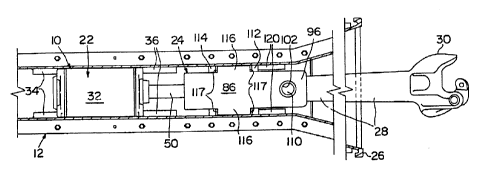
Self-positioning rail car cushioning unit 10 is mounted in
one end of rail car center sill 12_ The sill has a rectangular
cross section with opposed side walls 14 and top wall 16. Bottom
support plates 18 are secured to flanges at the lower ends of side
walls 14 to hold unit 10 in place. The outer end of the sill is
flared to permit swinging of dz~awbar 28.
Unit 10 includes a gas charged hydraulic cylinder 22 and an
elastamer spring yoke assembly 24. The hydraulic cylinder is
located in the pocket away from the enlarged open end 26 of the
sill and the yoke assembly is located between the cylirider and end
26. Drawbar 28 is Connected to the yoke assembly and extends
outwardly from the sill to knuckle coupler 30_
5
CA 02202568 1997-04-14
Cylinder 22 includes a cylindrical body 32 whzch is held in
place in the inner portion of the pocket between opposed paixs of
opposed stop blocks 34 and 36 secured on the inside of sill side
walls 14. The blocks 32 and 34 hold the cylinder body against
movement along the sill.
As illustrated in Figure 8, cylinder 22 includes rear head 38,
front head 40, exterior cylinder 42 -extending between the heads and
inner piston cylinder 44 also extending between the heads_ Piston
46 is fitted within cylindex 44 and is provided with sealing and
IO bearing rings 48 engaging the interior wall of cylinder 44. In
Figure 8, the piston is in a neutral position between heads 38 and
40. Piston rod 50 is joined to piston 46 and extends outwardly of
body 32 through opening 52 in front head 40 toward the yoke
assembly. High pressure seals S4 are provided in opening 52. An
enlarged mounting element or head 56 is provided on the free end of
rod S0.
Piston 46 divides the space within piston cylinder 44 into a
cylindrical buff chamber 58 located between the piston and the rear
head and an annular draft chamber 60 surrounding piston rod SO and
between the piston and the front head 40. Annular~chamber or
reservoir 62 is located between cylinders 42 and 44 and extends
between heads 38 and 40.
The interior chambers in hydraulic cylinder 22 are charged
with a fluid mixture of hydraulic oil and high pressure nitrogen
gas. Sufficient hydraulic oil is charged into the cylinder to
completely fill chambers 58 and 50 with oil W th separated nitrogen
6
CA 02202568 1997-04-14
gas filling the top of reservoir 62. In practice, buff or draft
movement of the piston in the cylinder mixes the nitrogen with the
hydraulic oil to form a froth that fills the interior chambers.
The nitrogen is preferably charged at a pressure of 50o p.s.i.
Movement of the piston and rod in body 32 flows the hydraulic
fluid between the various chambers through a number of valves
illustrated in Figures 8, 9 and 10_ A plurality of large area one
way check valves, like valve 64 shown in Figure 8, are provided in
front head 40 surrounding opening 52. Each check valve 64 includes
a ball valve member located in a passage communicating reservoir 62
and draft chamber 60. The check valves permit free flow of
hydraulic fluid from the reservoir 62 into the draft chamber during
movement of the piston 46 toward rear head 3s. During movement of
the piston toward the front head 40 the valves close to prevent
flow of hydraulic fluid through the passages from the draft chamber
into the resercroir _
A number of large area one way check valves 66 are mounted in
the end of piston cylinder 44 adjacent rear head 38 and communicate
reservoir 62 and buff chamber 58. These valves permit free flow of
2o hydraulic fluid from the reservoir into the buff chamber during
movement of the piston toward the front head 40 but prevent flow of
hydraulic fluid out of the buff chamber 58 during movement of the
piston toward the rear head 38. valves 64 could be located in the
adjacent end of cylinder 44. valves 66 could be located in head
38.
CA 02202568 1997-04-14
In Figure 8, piston 46 is shown in a neutral positzon located
slightly more than 2 inches from the front head and slightly more
than 10 inches from the rear head. The piston moves toward the
front head along a draft stroke of z inches without engaging the
front head and moves toward the rear head during a buff stroke of
inches without engaging the rear head. When in the neutral
position, the sealing and bearing rings 48 on piston 46 engage a
cylindrical band 68 on the interior surface of piston cylinder 44,
shown in Figure 9.
10 A number of spring backed flow control valves are mounted in
bores extending through cylinder 44 and communicate the reservoir
62 with the interior of the cylinder. Sets of like spring backed
check valves 70, 72 are located to either side of band 68. A set
of spring backed valves 70 are located in the cylinder between band
68 and the front head 40. A set of spring backed valves 72 are
located in the cylinder between the band 68 and rear head 38.
During buff movement of piston 46 from the neutral position toward
rear head 38 the rings 48 pass over and close valves 72. The
rings, however, do not close one way valves 66. During draft
movement of piston 46 toward head 40 rings 48 pass over and close
valves 70. '
Each spring backed check valve 70, 72 is fitted in a large
diameter bore extending into the outside of cylinder 44 surrounding
a smaller flow orifice 74 formed in the inner wall of cylinder 44.
A spring backed moveable valve member 76 is confined within body 75
and is biased by spring 78 toward the orifice to normally close the
8
CA 02202568 1997-04-14
orifice. A pair of bleed apertures 80 and 82 extend through
cylinder a4 to either side of band &8. Aperture 80 is immediately
adjacent the side of the piston facing front head 40 and aperture
82 is immediately adjacent the side of the piston facing rear head
38.
Elastomer spring yoke assembly 24 includes a metal yoke or
body 84 with spaced apart top and bottom straps 86 and 88 joined by
front and rear vertical walls 90 and 92 to define an elastomer
spring pocket 94 located in the body and extending between the sill
l0 side walls 14. The straps project forward of wall 90 to form front
stxap ends 96 and 98 located above and below socket loo in the
exterior face of wall 90. Pin bores 102 extend through front strap
ends 96 and 98. The top and bottom straps also extend rearwardly
beyond rear wall 92 to form hooked rear ends or mounting members
104 and 106. Piston rod head 56 is fitted in a recess 108 located
between the hook ends 3.04 and 106 and rear wall 92 so that the yoke
assembly 24, piston rod 15 and piston 46 are joined and moved back
and forth together along sill 12.
Drawbar 28 is secured to body 84 by vertical pin 110 which
extends through bores 102 and a passage in the butt end of the
drawbar. As illustrated in Figure 2, the butt of the drawbar is
seated in socket 100_
Front and rear stop plates 112 and 114 are fitted in the front
and rear ends of pocket 94 and normally engage front wall 90 and
rear wall 92, respectively. As illustrated in Figure 1, the ends
of plates 112 and 114 extend laterally to either side of body 84_
9
CA 02202568 1997-04-14
The body includes centrally located top and bottom lateral ears 116
shown in Figures 1 and 3. Forward and rear contact surfaces 117 on
the sides of the ears axe normally located inwardly from the walls
90 and 92.
An elastomer spring 118 is compressed and fitted in pocket 94
between plates 112 and 114. The spring includes a stack of flat,
- resilient elastomer pads formed from styrene-butadiene rubber of
the type marked under the trademark KEY-GAD by Keystone
Industries, Inc. assignee of the present application. The
elastomer spring 118 is preloaded. When in the neutral position,
the elastomer spring has a 15,000 pound compression force holding
the plates 112 and 114 against walls 90 and 92.
When device 10 is in the neutral position shown in Figures 1
and 2, the outer ends of plate 112 are held against a pair of
vertical stop blocks 120 mounted on sill inner walls 14 adjacent
the outer end of the sill. In this position, the adjacent contact
surfaces 117 of ears 116 are located 2 inches from blocks 12o and
the adjacent contact surfaces of ears 116 are located to inches
from blocks 36.
Unit 10 is held in the neutral position by the pressure of the
hydraulic fluid acting on the large area front face of the piston.
The pressurized fluid exerts a force of 5,000 pounds biasing the
piston toward the end of the sill. This force holds the yoke
assembly in the neutral position with the ends of plate 112
engaging stop blocks 120. The 5,000 pound gas pressure force
exerted on the piston is less than the 15,000 pound preload
l~
CA 02202568 1997-04-14
compression force of the elastomer spring 118 and does not compress
the elastomer spring.
From the neutral position cushioning unit to has a maximum
buff stroke of l0 inches from the neutral position before ears 11&
engage stop blocks 36 and a maximum draft stroke of 2 inches
before the ears engage stop blocks 120_ Piston 46 is directly
connected to coupler 30 through the piston rod S0, yoke assembly'
body 84 and drawbar 28 and moves with the coupler during buff and
draft strokes. At the end of the full 10 inch buff stroke the
30 piston is adjacent rear head 38 and partially covers the flow
passages in check valves 66.
The Figure 11 illustrates buff and draft performance of unit
to as presently understood and shoes static and total compression
forces generated by unit 10 in both buff and draft directions.
Total compression forces are shown for different energy impacts.
The horizontal axis represents the position of the coupler away
from the neutral position of Figures 3. and 2 during buff and draft
strokes. The unit has a maximum 2 inch stxoke to the left in draft
and a maximum 10 inch stroke to the right in buff. The vertical
axis of the Figure 11 graph represents the reaction or compression
force of the unit in thousands of pounds. The upper right hand
portion of the graph represents performance of the unit in buff and
the lower left hand portion represents performance of the unit in
draf t _
Curve 122 represents the static compression force curve for
unit 10 as the unit is moved from the neutral position along the 10
z1
CA 02202568 1997-04-14
inch buff stroke. During the first 8 inches of stroke from the
neutral position the static compression force is 75,000 pounds.
The static foxce is the total of a 70, OOO pound force resisting
movement of piston 46 toward rear head 38 required to pressurize
the hydraulic fluid in chamber 58 sufficiently to crack valves 72
open and allow hydz~aulic fluid to flow out from the chamber 58, and
a 5,000 pound force exerted on the face 135 of the piston 46 by the
pressurized hydraulic fluid in cylinder 22. The 5,000 pound force
and the 70,000 pound force are essentially constant throughout the
l0 buff stroke. If the buff impact force exerted on the coupler is
below or falls below 75,000 pounds, valves 72 close and buff motion
of unit 10 stops.
During initial 8 inches of buff stroke, elastomer spring 118
is moved inwardly with the yoke assembly 24 but is not compressed.
At 8 inches of stroke, plate 114 engages Stops 36 to join the
elastomer spring to the hydraulic cylinder 22 so that during the
final two inches of buff stroke the elastomer spring and hydraulic
spring are coupled together in parallel and the static compression
force for unit 10 is the sum of the compression forces for the
z0 hydraulic cylinder and the elastomer spring.
The elastomer spring is preloaded in pocket 94 and exerts a
15,000 pound force holding plates 112 and 114 against walls 9o and
92. When the unit l0 has been moved 8 inches from the neutral
position along the buff stroke the static compression force is
increased from 75,000 pounds to 90,000 pounds because of the
elastomer spring preload. This increase is represented by the
12
CA 02202568 1997-04-14
vertical Step ~.n curve 122 at the 8 inch positi.on_ During the
final 2 inches of movement along the buff stroke the static
compression force for unit 10 is the sum of the static compression
force for cylinder 22 and the compression force for the elastomer
spriz~g. This force increases very rapidly to 250,000 pounds at a
full 10 inch stroke.
The curves 124, 126 and 128 illustrate the total compression
force for unit l0 as the unit is moved from the neutral position
along the buff stroke in response to buff impacts exerted on
l0 coupler 30_ Curve 124 illustrates a relatively low energy buff
impact. The curves 126 and 128 represent higher energy buff
impacts. The difference between curve 122 and each of curves 1.24,
126 and 128 represents the hydraulic compression force for the
impacts generating curves 124, 126 and 128.
When coupler 30 is impacted in a buff direction the resultant
force is transmitted to the yoke body and piston. Cushioning unit
to does not move along the buff stroke until the coupler force
exceeds the 75,000 pounds static force required to open valves ~2
and permit hydraulic fluid to flow from chamber 58. When the
coupler force exceeds '75,000 pounds the cracking pressure for
valves 72 is exceeded, the valveB open and the piston moves toward
the rear head_ The extent to which the valves are opened depends
upon the energy of the impact. Low energy impacts, as represented
by curve 124, open the valves partially to permit relatively low
speed movement of the piston toward the rear head. High energy
impacts, as represented by curve 128, fully open the valves and
13
CA 02202568 1997-04-14
permit the piston to move more rapidly toward the rear head. The
hydraulic compression force resulting from flowing hydraulic fluid
out through open valves 72 depends upon the open area of flow
orifices 74 _ The maximum orifice areas for val~cres ~z and the
placement of the valves along the length of cylinder 44 are chosen
to maintain an essentially constant hydraulic compression force
along the buff stroke, as indicated by the flat portions of the
curves 124-128. In practice, these poxtions of the curves may be
somewhat iz~regular due to changes in the cross sectional area
l0 available for flowing hydraulic fluid out of chamber 58 as the
piston 46 passes over and closes valves and due to the 15,000
pounds compression force increase at 8 inches of stroke. The
relatively high, uniform hydraulic compression force for unit 10
assures impact energy is efficiently absorbed during the buff
stroke and motion of the coupler in the buff direction is smoothly
and safely slowed to protect lading from high inertia
accelerations. During the buff stroke hydraulic fluid is flowed
from chamber 58 into chamber 62 through salves 72 and from chamber
62 into chamber 60 through val~res 64.
Curve 124 illustrates that unit 10 exerts an essentially
uniform compression force of 135,000 pounds along the buff stroke
until motion of the coupler in a buff direction slows at about 7
inches of stroke to reduce the hydraulic compression force so that
the total compression force rapidly decreases to the static
compression force of 75,000 pounds. when this occurs, the
14
CA 02202568 1997-04-14
remaining open valves 72 in front of piston 46 close and buff
movement of the piston, yoke assembly and coupler stops_
After buff movement stops, the 5,000 pound gas pressure force
on the front face of piston 4& slowly returns the piston, yoke
assembly and coupler to the neutral position. At this time check
valves 66 open to permit hydzaulic fluid to flow from reservoir 62
into chamber 58. Spring backed valves 70 and 72 and check valves
64 are closed. Hydraulic fluid in draft chamber 6o is pressurized
and flows out from the chamber through both bleed apertures 80 and
l0 82 and then bleed aperture 80 only. The pressure of the hydraulic
fluid continues to move the piston toward the neutral position
shown in Figure 8 until plate 112 contacts atop blocks 120. In
this position, bleed aperture 80 is located closely adjacent to the
end of the sealing ring 48 adjacent front head 40.
Curve 126 is similar in shape to curve 124 and shows the total
compression force for unit l0 when subjected to a higher energy
buff impact than the impact for curve 124. The h~.gher energy
impact of curve 124 results in a constant level total compression
force of about 155,000 pounds through a stroke greater than 8
inches_ The total compression force increases by 15,000 pounds
when the stroke exceeds 8 inches, due to coupling of the elastomer
spring to the hydraulic spring_ Aa impact energy is absorbed by
unit l0 the buff motion of the coupler slows and the hydraulic
compression force exerted by cylinder 22 is reduced until the total
compression force falls to about 120,000 pounds where curve 126
intersects the static compression force curve 122_ At this point,
CA 02202568 1997-04-14
all impact energy has been absorbed, and buff movement of the
coupler along the buff stroke stops_ The unit then returns to the
neutral position as previously described and spring 118 expands to
the position of Figure 1_
Curve 128 illustrates the total compression force for a
relatively high enezgy buff impact. The energy imparted by this
impact is absorbed by unit l0 as described in connection with the
lower level energy impact of curve 126.
Curves 132, 134 and 136 illustrate the total compression force
to for unit 10 in response to the successively higher energy draft
impacts exerted on coupler 30. A draft impact exerted on coupler
3o sufficient to move the coupler in a draft direction must be
greater than 80,000 pounds. This figure represents the total of a
70,000 pound force required to pressurize hydraulic fluid in draft
chamber 6o sufficiently to crack open valves 70, plus the 15,000
pound preload of elastomer spring 118, less the 5,000 pound gas
preload exerted on the front face of the piston 46 and biasing the
piston in the draft diz'ection
If the draft impact force is greater than 80,000 pounds then
valves ~o open and the coupler, yoke assembly and piston are moved
in the draft direction along the draft stroke. 'fhe extent to which
the valves open depends upon the impact energy, as previously
described. Curves 132, 134 and 136 shown in Figure 11 illustrate
the total compression force of unit 10 resisting draft movement of
2s coupler 3g for d~ fferent ~nergry impacr.s, This fore is the tl~tal
16
CA 02202568 1997-04-14
compression force resulting from high speed flow of hydraulic fluid
through open valves 70 less the 5,000 pound gas preload. As
illustrated, the total compression force of unit 10 increases
rapidly from the 80,000 pound cracking pressure to a peak. As
draft movement of the coupler slows, the hydraulic force decreases
and the total force falls to intersect curve 130. At the
intersection points of curves 132, 134 and 136 with curve 130 the
draft movement of the coupler is stopped and the total compression
force falls to zero. Spring 118 then expands to return the
coupler, yoke assembly and piston 46 back to the neutral position.
During return of the piston to the neutral position hydraulic fluid
flows out of chamber 58 through the bleed aperture 82. When spring
218 is fully expanded the pressure of the hydraulic fluid on piston
46 holds plate 112 against wall 90 and the piston is returned to
the neutral position.
Curves 124, 126, 128 and 132, 134 and 136 represent the
compression forces exerted by unit to in absorbing buff impacts
resulting from train make up, and buff and draft impacts resulting
from train action events. Higher energy impacts would result in
2o more rapid movement of piston 46 away from the neutral position,
more rapid flow of hydraulic fluid out through the spring backed
valves and corresponding higher hydraulic compression forces
required to absorb higher impact energies. Unit to is self-
centering and returns to the neutral position after impact energy
has been absorbed_
17
CA 02202568 1997-04-14
Buff and draft impacts on coupler 30 during normal operation
have a total energy insufficient to fully collapse the unit l0 in
buff or draft. Very high energy impac~.s may fully collapse the
unit in buff or draft, leaving residual unabsorbed energy. The
residual energy is dissipated by bottoming contact with stop blocks
36 and 120. while residual energy bottoming can injure lading,
efficient energy absorption by unit 10 reduces the likelihood of
injury. very high energy impacts are infrequent_
Initial movement of piston 46 in the buff direction moves ring
48 over aperture 82 to close the aperture. Likewise, initial draft
movement of piston 46 toward head 42 moves the ring 48 over
aperture 80. Apertures 80 and s2 are rapidly closed during
cushioning of buff and draft impacts and do not flow appreciable
amounts of hydraulic fluid from chambers 58 and 60.
During buff collapse of cylinder 22 the interior volume of the
cylinder is decreased by the volume of piston rod 50 extended into
the cylinder. The decrease in volume increases the gas pressure
and increases the static pressure resisting movement of the piston
toward rear head 38. The increase in the gas pressure static
compression force in buff and corresponding increase in draf t are
small and are ignored in Figure 11.
valves 72 crack open when the pressure of the hydraulic fluid
in chamber 58 is increased to 1,585 p_s.i_ by a buff impact force.
Valves 70 crack open when the pressure of the hydraulic fluid in
chamber 60 is increased to 2,026 p_s_i. by a draft impact force.
The buff impact force increases the pressure of the fluid in
18
CA 02202568 1997-04-14
chamber 58 less than the corresponding increase in pressure in
chamber 60 from a draft impact force because the area of the piston
facing the buff chamber 58 is greater than the area piston facing
the draft chamber 60.
The increases in hydraulic fluid pressure required to open
valves 70 and 72 are adjusted to control impact accelerations and
limit lading damage, dependent upon the weight of the coupled rail
cars and the nature of the lading. X111 valves provide effective
hydraulic resistance and energy absorption when fully open. In
practice, the buff and draft pressure increases required to open
valves 7o and 72 far different weight cars and different ladings
may vary from a loc~r of 1, 100 p . s . i . in buff to a high of 3 , 600
p_a.i. in draft.
While we have illustrated and described a preferred embodiment
of our invention, it z.s understood that this is capable of
modification, and we therefore do not wish to be limited to the
precise details set forth, but desire to avail ourselves of such
changes and alterations as fall within the purview of the following
claims.
19