Note: Descriptions are shown in the official language in which they were submitted.
CA 02202695 1997-04-15
a.'
ARTICULATING PRESSURE CONDUIT
FIELD OF THE INVENTION
This invention relates to a novel method and
apparatus for joining vessels. More particularly, this
invention pertains to a novel method and apparatus for
connecting vessels which have equal or different internal
pressures, or which are surrounded by equal or different
pressures to permit transport between the connected
vessels.
BACKGROUND OF THE INVENTION
A problem which occurs frequently under water, or
in space, is the joining or connection of pressurized
vessels that are under equal or different internal pres-
sures, or are subjected to equal or different external
pressures. For instance, a serious challenge occurs at
underwater depths when attempts are.made to join a rescue
vessel to a disabled submarine. Often the disabled submar-
ine is not level or upright and it is difficult or,imposs-
ible to connect a rescue vehicle to the escape hatch in
order to allow the crew in the submarine to be transferred
into the rescue vessel, and transported to the surface.
Another problem presents itself in the joining of
a personnel, transfer or workover capsule to a submerged
sub-sea petroleum well head. Further problems present
themselves in joining two or more pressurized vessels in
the vacuum or near vacuum of space, or in the upper atmos-
phere, or under any condition where differential pressures
are present, or extremely inhospitable temperatures are
encountered.
A submarine rescue situation provides a good
example of the inherent problems that must be dealt with
and overcome. There are many accidental situations that
may occur to cause a submarine to become disabled and
CA 02202695 1997-04-15
,.=.
2
unable to return to the surface. Submarines have an escape
hatch fitted to the upper section of the pressure hull to
allow'the occupants to transfer to a rescue device, either
a small submersible or a rescue bell, and be returned to
the surface in that manner. The rescue device is fitted
with a lower trunk, which is cylindrical or often in the
shape of a partial hemisphere that has a relatively soft
polymer mating gasket on its outboard edge.
U.S. Patent No. 3,987,742, granted October 26,
1976, discloses a typical apparatus and method for dealing
with an underwater rescue problem. This U.S. patent
discloses an air lock with a sealing ring to.couple an
underwater rescue craft to the escape hatch of a submarine.
The air lock consists*of a bell, fastened around the hatch
of the craft and a jacket section shaped like a ball joint,
and retained with a small amount of free play. The pro-
jecting end carries the sealing ring. The inner end of the
ball joint section has a groove to accommodate the ring,
sealing it against the bell. The internal circumference of
the free bell end has a similar groove with a sealing ring.
The space between ball joint section bell and sealing rings
is filled with a lubricating fluid maintained at a pressure
sl~ghtly different from the hydrostatic pressure. The
constant differential between the two pressures is ad-
justed, so that the apparent weight of the movable jacket
is neutralized to give a hydrostatic buoyancy inside the
bell.
Most rescue devices have a limited ability to
assume any position in the water column other than upright.
The limited change in attitude of the rescue device from
the vertical may be effected by the shifting of ballast air
and water, the movement of a weight, or the temporary
thrusting of a propulsar. In each configuration, there is
inevitably some degree of misalignment between the mating
surfaces of the rescue device and the disabled submarine.
CA 02202695 1997-04-15
. .. . l==, {
- 3 -
Beyond some range of misalignment, the rescue device cannot
mate and effect a seal with the disabled submarine. The
mating hatch surface of the disabled submarine is almost
always "off square" in more than one plane. That is, the
hull of the disabled submarine is not level fore and aft,
and is rolled some degree off plumb in its circumference.
Some rescue devices make use of a cable attached to the
hatch of the disabled submarine to winch the rescue devic'e
down to the submarine but the rescue device is still re-
quired to move off its vertical axis in order to line up
with the disabled submarine. In some cases, the physical
size of the rescue device relativeto the length of. the
mating trunk precludes joining unless the disabled submar-
ine is close to plumb.
U.S. Patent No. 4,549,7S3, granted October 29,
1985, Rene T. Nuytten, discloses and claims a first form of
rotary joint which is useful in underwater conditions, for
example, deep-sea diving suits, and which can be con-
structed in such a way such that resistance to rotational
movement or the potential for leakage, does not increase
substantially with moderate external pressure on the joint.
This rotary joint is suitable for use in conditions where
theexternal pressures are not too great.
Preferably, the joint has a sealing member, a
retaining member, and a central member disposed axially
between the sealing and retaining members. The central
member has an annular first end dimensioned and axially
slidably mounted on a retaining end of the retaining member
so as to define a first variable volume chamber therebe-
tween. The central member also has a second end with inner
and outer extending annular bearing members, each concen-
tric with, and normally rotatably abutting a corresponding
sealing surface portion on the sealing member, so as to
define annular side walls of a second chamber. The second
chamber is interconnected with the first chamber.
CA 02202695 2006-06-15
- 4 -
U.S. Patent No. 4,903,941, granted
February 27, 1990, Rene T. Nuytten, discloses and claims
a second form of pressure equalizing rotary joint which
can function readily at underwater depths where external
pressures are great. This novel rotary joint seeks to
equalize exterior and interior pressure. This rotary
joint is useful in permitting free rotary motion between
two components connected by the joint in conditions where
unequal pressures exist at the interior and exterior of
the joint. It includes a rotary joint comprising:
(a) first annular member means adapted to be connected
to the end of a first tube-like object; (b) second
annular member means adapted to be connected to the end
of a second tube-like object; (c) intermediate member
means adapted to be positioned between the first annular
member means and the second annular member means and
being capable of moving independently of the first and
second annular member means, said intermediate member
means defining a first chamber between said intermediate
member and the first annular member and a second chamber
between said intermediate member and said second annular
member; (d) first sealing means associated with the
first annular member means and the intermediate member
means and adapted to seal the first chamber from the
interior and exterior of the joint; (e) second sealing
means associated with the second annular member means and
the intermediate member means and adapted to seal the
second chamber from the interior and exterior of the
joint; and, (f) resilient valve means adapted to enable
pressure in the first chamber and pressure in the second
chamber to seek to equalize when the respective pressures
are unequal.
CA 02202695 2006-06-15
- 5 -
SUMMARY OF THE INVENTION
In accordance with one aspect of the present
invention there is provided an articulating apparatus for
connecting first and second underwater vessels having any
internal and external pressure configuration relative to
each other, each vessel having an orifice, comprising: a
first and second hollow wedge shaped segment; said first
hollow wedge shaped segment, having first and second
orifices, said first orifice being connected to an
orifice in the first vessel by a first rotary bearing and
seal assembly; said second hollow wedge shaped segment
having first and second orifices, said second orifice
having a sealing gasket around its circumference for
sealing around the orifice in the second vessel; a
second rotary bearing and seal assembly interconnecting
said second orifice of said first hollow wedge shaped
segment with said first orifice in said second hollow
wedge shaped segment; said first hollow wedge shaped
segment can be rotated relative to said orifice in said
first vessel by means of said first rotary bearing and
seal assembly; said second hollow wedge shaped segment
being rotatable relative to said first hollow wedge
shaped segment by means of said second rotary bearing and
seal assembly; and said first and second segments being
configured such that said second segment can be rotated
from a first position where the plane of said second
orifice of said second segment is substantially parallel
to the plane of said first orifice in said first segment
through an angle of approximately 180 degrees.
In accordance with another aspect of the
present invention there is provided a method for
CA 02202695 2006-06-15
- 6 -
connecting first and second underwater vessels having any
internal and external pressure configuration relative to
each other, said first vessel having a first orifice
therein, said second vessel having a second orifice
therein, comprising: interconnecting said first orifice
on said first vessel to a first hollow wedge shaped
segment having first and second, open ends, said first
end of said first segment being connected to said first
vessel; connecting said first segment to a second hollow
wedge shaped segment having first and second open ends,
said first end of said second segment being connected to
said second end of said first segment, a first rotary
bearing and seal assembly interconnecting said first end
of said second segment and said second end of said first
segment, said first rotary bearing and seal assembly
permitting said second segment to rotate relative to said
first segment while said first and second segments are
maintained in abutting relationship to one another, said
first and second segments being configured such that said
second segment can be rotated from a first position
wherein an imaginary, first plane passing through and
parallel to the opening defined by said first open end of
said second segment is transverse to an imaginary, second
plane passing through and parallel to the opening defined
by said first open end of said first segment to a second
position wherein said first and second planes are
substantially parallel; and connecting the second end of
said second segment to said second orifice in said second
vessel.
In accordance with yet another aspect of the
present invention there is provided a method for
connecting vessels having any relative internal pressure
CA 02202695 1997-11-07
- 7 -
restricting the spirit or scope of the invention in any way:
Figure la illustrates a front view of an embodiment
wherein the articulating pressure conduit is arranged so that
the joining flanges provide parallel exterior connecting
surfaces.
Figure lb illustrates a front view of an embodiment
wherein the articulating pressure conduit is arranged so that
the flanges provide exterior surfaces which are at 45 to one
another.
Figure 2 illustrates a front view of an articulating
conduit attached to the bottom of an autonomous submersible
personnel transfer device.
Figure 3 illustrates a side view of an autonomous
submersible personnel rescue vehicle with the articulating
conduit arriving at the exterior surface of a disabled
submarine.
Figure 4 illustrates a side view of an autonomous
submersible personnel rescue vehicle with a connecting tether
to the exterior of the disabled submarine, and the
articulating conduit arranged so that the exterior surface of
the conduit is parallel to the mating surface of the disabled
submarine.
Figure 5 illustrates a side view of the autonomous
submersible personnel rescue vehicle with the articulating
conduit connected to the mating surface of the disabled
submarine in preparation for personnel transfer from the
submarine into the rescue vehicle.
CA 02202695 1997-04-15
- 8 -
Figure 6 illustrates a front view of a remotely
operated submersible rescue vehicle with an articulating
conduit on the underside of the remotely operated vehicle.
Figure 7 illustrates a front view of an embodi-
ment whereby two remotely operated vehicles with articulat-
ing conduits are connected'in series to one another.
Figure 8 illustrates a detailed section view.of
the articulating component's of the articulating conduit,
including the annulus seal arrangements.
Figures 9a to 9d illustrate sequential views.
Figure 9a illustrates a side view of a submers-
ible rescue vehicle and articulating conduit being lowered
by an umbilical tether.
Figure 9b illustrates a front view of a submers-
ible rescue vehicle, and articulating conduit with umbili-
cal tether, lowering a connecting tether to a disabled
underwater submarine.
j ' Figure 9c illustrates a side view of a submers-
ible rescue vehicle and articulating conduit with umbilical
tether, connected to the escape hatch of an underwater
disabled submarine.
Figure 9d illustrates a side view of the sub-mersible rescue vehicle and
articulating conduit being
raised from the underwater disabled submarine, after
personnel have been transferred into the rescue vehicle.
Figure 10 illustrates a detailed front view of
the power accessories which operate an articulating con-
duit.
CA 02202695 1997-04-15
- 9 -
Figure 11 illustrates a detailed front section
view of a distinctive embodiment of a thrust-powered
submersible rescue vehicle, with articulating conduit,
grappling accessories, variable ballast and power acces-
sories which operate the articulating conduit.
Figure 12 illustrates-a detailed section view of
the components of an articulating conduit connected to the
escape hatch of a disabled underwater submarine, disposed
at an.angle.
Figure 13 illustrates a detailed front section
view of the components of an articulating conduit connected
to the upright escape hatch.of a disabled underwater
submarine.
DETAILED DESCRIPTION OF THE PREFERRED EMBODIMENT
This invention relates to an apparatus and method
of joining vessels that are at equal or different internal
pressures, or that are surrounded by equal or different
external pressures, to effect a conduit between the
vessels. The conduit can be used for the transference of
meri}ormaterial from one vessel to another, once a sealed
connection has been made.
The conduit and its herein described embodiments
have the capability to articulate so as to provide a mating
flange surface that will be parallel to the target mating
surface - even under a wide variety of conditions of
misalignment.
This apparatus is useful, for example, in the
joining of a rescue vessel to the escape hatch of a dis-
abled submarine to allow the crew to be transferred to the
surface. It is also useful in the joining of a personnel
CA 02202695 1997-11-07
- 10 -
transfer or work-over capsule to a submerged sub-sea petroleum
well-head, or for joining two or more pressurized vessels in
the vacuum or near vacuum of space or the upper atmosphere,
or any such condition where differential pressures are
present. Mis-matched flanges must be mated under such
differential pressures or must be moved into alignment under
differential pressures.
Referring to the drawings, Figure la illustrates a front
view of an orientation wherein the articulating pressure
conduit is arranged so that the bottom surface of the mating
tube and flange 4, and first rotary bearing and seal 6, is
parallel with the bottom surface of lower wedge segment 14 and
lower circular sealing gasket 18. This orientation is
achieved by arranging the rotational configuration of upper
wedge segment 10 and lower wedge segment 14 so that the broad
sides of their respective wedge shapes are dramatically
opposite to one another.
Figure lb illustrates a side-section view of an
articulating pressure conduit according to the invention. The
articulating pressure conduit 2 is constructed of a mating
tube and flange 4 which is connected by a first rotary bearing
and seal 6 to the top of an upper wedge segment 10, which is
hollow. The rotary orientation between the mating tube and
flange 4 and upper wedge segment 10, via first rotary bearing
and seal 6, is controlled by upper drive motor 8. Upper drive
motor 8, by means of gears, racks, cables, hydraulic
cylinders, or levers (not shown in Figure lb, but shown later
in Figures 10, 11, 12 and 13) rotates upper wedge segment 10
about the circular first rotary bearing and seal 6 and
relative to mating tube and flange 4.
The bottom surface of hollow upper wedge segment 10 is
rotationally connected to the top of lower hollow wedge
segment 14 by lower rotary bearing and seal 16. The rotary
CA 02202695 1997-11-07
- 11 -
orientation of lower wedge segment 14 relative to upper wedge
segment 10 is controlled by lower drive motor 12. The bottom
circular surface of hollow lower wedge segment 14 has a
circular sealing gasket 18 about its circumference.
The apparatus 2 can use the connecting joint and seal
geometry described in either U.S. Patent No. 4,549,753, or
U.S. Patent No. 4,903,941, both of which are incorporated
herein by reference. The two angled or wedge segments 10 and
14 of the conduit are rotated on pressure equalizing rotary
joint surfaces 6 and 16 relative to each other to provide a
deflection off a centre line. A bearing and seal assembly as
described in either of these two patents is suitable required
to contain or exclude pressure differentials and to transfer
the load from one wedge segment of the apparatus to another,
whilst still allowing rotation under extreme pressures.
The bearing and seal may be of an unbalanced type where
there is no pressure differential when the segments are
initially required to rotate to a parallel mating position,
and the segments are not required to move after a "pump-down",
or a differential pressure situation has been initiated.
Alternatively, the bearing and seal assembly can be of
a balanced type, such as that described in U.S. Patent
No. 4,903,941. This design allows the conduit to continue to
flex or rotate, even under relatively high pressure
differentials, and to be locked in a final position
mechanically rather than by the effect of pressure on the seal
and bearing - which is the case in the unbalanced version.
The articulating pressure conduit 2 is ar-
CA 02202695 1997-04-15
- 12 -
ranged so that the bottom surface of the mating tube and
flange 4 and the bottom circumferential surface of the
lower wedge segment 14, and lower sealing gasket 18 are
disposed at an angle of about 45 to one another. This
orientation is achieved by rotationally configuring the
broad surface of upper wedge segmer_*. 10 and the broad
surface of lower wedge segment 14 so that they coincide
with one another. Likewise,the thin sides of the respect,-
ive wedges -10 and 14 are coincident with one another.
Similarly, three wedges may be used, instead-of two, to
accept an offset of approximately 90 .
In a preferred configuration, the articulating
conduit is attached to the bottom of a personnel transfer
device, such as a tethered diving bell or an autonomous
submersible 20, as shown" in Figure 2. The wedge-shaped
segments 10 and 14 are rotated so that the lower mating
sealing gasket 18-is level-in the normal position.
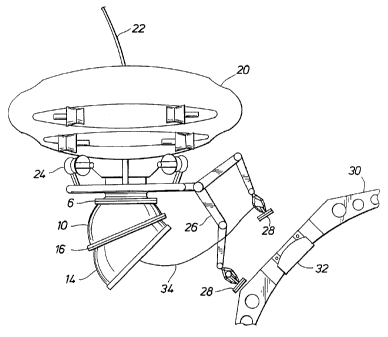
As illustrated in Figure 2, the autonomous
submersible 20 has a tether 22 which connects it to a
supply vessel which is located on the surface of the.water
body above the autonomous submersible 20. The position of
the submersible 20 is controlled by a series of propellers
24,-~'wM:ch provide thrust in various directions, and can be
controlled by the operator of the submersible 20, or from
the supply vessel. The submersible 20 is equipped with
extendible grappling arms 26, which have opening and
closing pincers, or other means of attachment, such as
suction cups, or electromagnetic feet 28, to assist the
submersible 20 in connecting with a submerged vessel, as
will be described in more detail below.
Figure 3 illustrates a side view of the auton-
omous submersible 20 with the articulating conduit compris-
ing upper wedge segment 10 and lower wedge segment 14 at a
depth where it has met with the exterior surface of a
CA 02202695 1997-04-15
r,=
- 13 -
disabled submarine 30. As seen in Figure 3, the rescue
submersible 20 has arrived at the disabled submarine 30,
determined that the mating surface (ie. escape hatch 32) of
the disabled submarine 30 is off plumb and has attached a
S haul-down tether line 34 to the disabled submarine 30.
Alternatively, as also illustrated in Figure 3, the pre-
liminary attachment linlc may be mechanical arms 26 and
grasping claws, magnetic feet 28, or a pump/suction. pod
(not.shown). These are employed until a seal (discussed
below in association with Figure 8) is made by pumping down.
the articulating conduit 2, or, in the case of a fully-
equalized mating where the rescue device, disabled submar=
ine, and ambient pressure are all the same, may be used'as
the primary means of attachment.
Figure 4 illustrates a front view of an auton-
omous submersible personnel rescue vehicle with a connect-
ing tether to the exterior of the disabled submarine, and
the articulating conduit arranged so that the exterior
surface of the conduit is parallel to the mating surface
of the disabled submarine.
Specifically, Figure 4 shows that the wedge-
shaped sections 10 and 14 of the articulating conduit have
beeA A~tated, by the rescue submersible pilot (not shown),
to bring the polymer 'mating gasket 18 on the bottom surface
of the lower wedge segment 14 parallel to the mating
surface of the escape hatch 32 of the disabled submarine
30. As seen in Figure 4, a grappling tether 34 and elec-
tromagnetic plate 36 have been lowered to and connected
with the disabled submarine 30. The tether 34 is then
hauled in to bring the bottom surfaces of the lower wedge
segment 14 and seal 18 adjacent to and parallel with the
escape hatch 32.
Figure 5 illustrates a side view of the auton-
omous submersible personnel rescue vehicle with the articu-
CA 02202695 1997-04-15
. ~....
- 14 -
lating conduit connected to the mating surface of the
disabled submarine in preparation for personnel transfer
from the submarine into the rescue vehicle. As seen.in
Figure 5, the autonomous submersible has been lowered by
tether 22, and, by having hauled in grappling tether 34,
has interfaced the lower sealing gasket 18 of lower wedge
segment 14, with the parallel exterior angled surface of
escape hatch 32. Once a seal is made, the segments 10 and
14 are pumped out and.the escape hatch 32' can be'opened.
Personnel 40 can then climb the ladder 38 into the interior
of lower wedge segment 14,* and then into upper wedge
segment 10, and finally into the interior of autonomous
submersible 20. Once the appropriate number of personnel
40 have been transferred into the submersible 20, lower
sealing gasket 18 is.detached from escape hatch 32 and the
submersible 20 is raised by tether 22 to the surface.
In an alternate embodiment, the articulating
conduit may take the form of an ROV (remotely operated
vehicle) fitted with thrusters, television cameras, lights,
sonar, and other optical/acoustic navigation/docking
electronics.
Figure 6 illustrates a front view of a remotely
opefat'ed submersible rescue vehicle (ROV) with an articu-
lating conduit on the underside of the remotely operated
vehicle. As illustrated in Figure 6, the remotely operated
vehicle 42 is navigated and controlled by a series of
propellers 44, which can be angled in the directions
required for propulsion in the appropriate direction. The
remotely operated vehicle 42 is equipped with grappling
arms 26 and magnetic feet 28. As with the submersible 20
described previously, the underside of the remotely oper-
ated vehicle 42 has connected there:to a first rotary
bearing and seal 6, an upper hollow wedge segment 10, a
lower rotary bearing and seal 16, and a lower wedge segment
14. A lower sealing gasket 18 is positioned around the
CA 02202695 1997-04-15
- 15 -
circumference of the bottom of lower wedge segment 14. The
upper surface of the remotely operated vehicle 42 is
equipped with a circumferential rescue submersible mating
surface 48. The remotely operated vehicle 42 is controlled
from the surface via control umbilical cord 48.
In this configuration, the conduit ROV 42 is
powered and controlled by an umbilical control 'tetlier 4,8
connected to the surface. Or it can be self-powered, for.
example, by batteries, and operated in an autonomous, pre-
programmed mode - or in an autonomous (no umbilical tether)
fashion where control is effected acoustically or optical-
ly.
The purpose of the ROV 42 is to attach the lower
sealing gasket 18 of the articulating conduit 10, 14 to a
disabled submarine 30 so as to provide a parallel mating
surface to the arriving rescue vehicle or device. -A unique
advantage of the ROV 42 is the ability to couple two or
more of the ROV conduit.assemblies 42 together, either on
the surf,ace or on the bottom, to thereby accept very large
degrees of misalignment, as can be seen in Figure 7.
Figure 7 illustrates a front view of an embodi-
ment whereby two remotely operated vehicles with articulat-
ing conduits are connected in series to one another. As
seen in Figure 7, a lower first ROV 42 has been coupled via
upper mating surface 46 with the lower sealing gasket 18 of
the lower and upper wedge segment combination 10, 14, of a
second ROV 50, which is controlled by a second control
umbilical tether 52. It is evident in Figure 7 that the
coupling of a first ROV 42 with a second ROV 50 enables a
90 connection to be made with the escape hatch of a
disabled submarine, or some other underwater sea vessel.
The combination illustrated in Figure 7 would be useful
where the disabled submarine has turned on its side and the
escape hatch faces in a horizontal rather than an upright
CA 02202695 1997-04-15
....
- 16 -
direction. It will be understood that three or more ROV 42
units can be connected in series with one another to
accommodate greater degrees of offset. For example, the
submerged vessel may be inverted and access must be made
underneath. In that case, several ROV units may be hooked
together in series to provide a"U" configuration.
.In the ROV mode, the articulating conduit 2 rrius;t
have some means of attaching to the disabled submarine hull10 30 in a secure
fashion prior to the arrival of the rescue
device 42. The ROV 42 may be fitted with a top hatch (not
shown) so that it can be pumped down and held in position
by. outside sea water pressure (as is normally the case with
the rescue device) or it may be held in position by any of
..15 the mechanical, magnetic, or pump-down devices previously
mentioned.
As an alternative to ariy of these hold-down
methods, the conduit ROV may have a lower seal that has two
20 concentric polymer rings with an anilulus between them.
Figure 8 illustrates a detailed section view of the articu-
lating components of the articulating conduit, including
the annulus seal arrangement. As seen in Figure 8, the
annulus seal 56 replaces the conventional lower sealing
25 gasket'118, as illustrated in Figure 1, with a cupped ring
configuration 56 which has a pump exhaust port 58. A pair
of concentric polymer sealing rings 60 are fitted onto the
exterior edges of the hollow ring 56. Once the annulus
seal 56 has engaged the surface of the escape hatch of the
30 disabled submarine, or other suitable surface, and the
seals 60 are engaged, a vacuum is drawn on the interior of
seal 56 by exhausting the contents through pump exhaust
port 58.
35 The annulus seal is pumped down in basically the
same fashion as the manner in which the entire trunk is
CA 02202695 1997-04-15
,....
- 17 -
pumped down in the rescue device mode, and the conduit ROV
is held firmly in position by outside sea water pressure.
Figure 9a illustrates a side view of a submers-
ible rescue vehicle and articulating conduit being lowered
by an umbilical tether. As seen in Figure 9a, the grappl-
ing tether 34 is held by grappling arm 26, and is ready for
dropping at the appropriate moment, by a control command
transmitted through umbilical tether 22.
Figure 9b illustrates a front view of a submers-
ible rescue vehicle, and articulating conduit with umbili-
cal tether, lowering a connecting tether to a disabled
underwater submarine. As seen in Figure 9b, the grappling
tether 34, with a magnetic plate 36 at the lower end
thereof, has been dropped ready for engagement with the
external surface of escape hatch 32 of disabled submarine
30.
Figure 9c illustrates a side view of a submers-
ible rescue vehicle and articulating conduit with umbilical
tether, connected to the escape hatch 32 of an underwater
disabled submarine. In the position illustrated in Figure
9c, the grappling tether 34 has been hauled into the
int'erior of conduit 10; 14, which is now engaged with the
external surface of escape hatch 32 of disabled submarine
30. Once pressures are equalized internally, and sea water
is pumped from the interior of conduit 10, 14, the escape
hatch 32 can be opened, and personnel 40 can be evacuated
via ladder 38 through the interior of conduit assembly 10,
14, into the interior of submersible 20.
Figure 9d illustrates a side view of the sub-
mersible rescue vehicle 20 and articulating conduit 10, 14
being raised from the underwater disabled submarine 30,
after personnel have been transferred into the rescue
vehicle 20.
CA 02202695 1997-04-15
= ~:
- 7.8 -
Figure 10 illustrates a detailed front view of
the power accessories which operate the articulating con-
duit. As seen in Figure 10, an upper drive motor 8, which
can be hydraulic or electrical, rotationally drives mating
tube and flange 4, via first rotary bearing and seal 6,
relative to upper wedge segment 10. In similar fashion,
lower drive motor 12 rotationally drives the lower wedge
segment 14 via lower rotary bearing and seal 16, relative
to upper wedge segment 10. Hydraulic hoses and water
pumping hoses 62 are shown connected to various points on
the whole upper wedge segment 10, lower wedge segment 14
assembly. These hoses,=and other equipment, are conven-
tional and do not represent part of the invention. They
enable the relative rotational positions of the upper wedge
segment 10 to be adjusted relative to mating tube and
flange 4, and in turn, lower wedge segment 14, to be
positioned relativeto upper wedge segment 10, via lower
rotary bearing and seal 16. Furthermore, some of the hoses
are used to pump sea water from the interior of upper wedge
segment 10 and lower wedge segment 14, once a water-tight
seal has been made between lower sealing gasket 18 and the
escape hatch of a disabled submarine, as explained previ-
ously in detail. The lower sealing gasket 18, in an
alterl~ative form, can be the annulus seal 56, which was
illustrated in Figure 8. Figure 10 also shows various
nipples, and other connections, to which hoses and the like
can be connected for pumping air into the interior of the
conduit assembly 10, 14, exhausting water from the interior
of the assembly and performing other functions required to
operate the conduit assembly 10, 14.
Figure 11 illustrates a detailed front section
view of an alternative embodiment of an autonomous submers-
ible rescue vehicle, with articulating conduit, grappling
accessories, and power accessories which operate the
articulating conduit. As seen in Figure 11, the submers-
CA 02202695 1997-04-15
arw
- 19 -
ible 64 is equipped with a pair of buoyancy tanks 66. The
upper and lower wedge segments 10, 14 are connected to the
underside of the submersible 64, via mating tube and flange
4, as described previously in association with prior
drawings.
Figure 11 illustrates by means of a network of
hydraulic cylinders 68, cable 70, and pulley 72, as con-
trolled by hydraulic pumps, or motorr, or alternatively,
pneumatic pumps, and motors, how the lower wedge segment 14
can be rotated relative to upper wedge segment 10,.via-
lower rotary bearing and seal 16, between a range of
rotational orientations whereby in one position, the lower
sealing gasket 18 is at approximately a 450 angle relative
to the horizontal bottom of submersible 64, to. another
opposite position where the lower sealing gasket 18 is
horizontal and parallel with the horizontal bottom of the
submersible 64. The hydraulic cylinder 68, cable 70 and
pulley 72, together with hydraulic and pneumatic motors,
and electric, motors, as illustrated in Figure 11, are
conventional. A motor driven rack and pinion system may
also be used to affect rotation.
Figure 11 also shows by means of arced lines the
rante *of positions that can be assumed. by grappling arms.
26, which also are controlled by conventional hydraulic or
pneumatic cylinders, or other suitable powering mechanisms.
Figure 12 illustrates a detailed front section
view of the components of an articulating conduit connected
to the escape hatch of a disabled underwater submarine,
disposed at an angle. As seen in Figure 12, the hydraulic
or pneumatic cylinders 68 have rotationally moved the lower
wedge segment 14 about lower rotary bearing and seal 16,
relative to upper wedge segment 10, so that the lower
sealing gasket 18 is parallel with and mates with the
CA 02202695 1997-04-15
'~F
- 20
external surface of escape hatch 32 of disabled submarine
30.
Figure 13 illustrates a detailed front section
view of the components of an articulating conduit connected
to the upright escape hatch of a disabled underwater
submarine. As seen in Figure 13, the lower wedge segment
14 has been rotated via hydraulic or pneumatic cylinders
68 and cable 70 relative to upper wedge segment 10, so that
the lower sealing gasket 18 is horizontal, and mates snugly
with the horizontal surface of escape hatch 32 of disabled
submarine 30. The orientation=illustrated in Figure 13
would be exceptional because it would be unusual for a
disabled submarine 30 to settle on the bottom of a body of
sea water.in a perfectly level position. However, the
combination of extremes illustrated in Figures 12 and 13
demonstrate the versatility of the conduit combination 10,
14.
As will be apparent to those skilled in the art
in the light of the foregoing disclosure, many alterations
and modifications are possible in the practice of.this
invention without departing from the spirit or scope
thereof. Accordingly, the scope of the invention is to be
con~trted in accordance with the substance defined by the
following claims.