Note: Descriptions are shown in the official language in which they were submitted.
CA 02202779 1997-04-1~
Wo 96/13819 PCT/US95113823
SELF-LOCATING REMOTE MONITORING SYSTEMS
Claim of Priority:
This application claims priority from US patent application, serial no. unknown, filed
October 23, 1995, entitled "Self-Locating Remote Monitoring Systems," docket no. SCHL-
5 002, which is a continll~tion-in-part of, and claims priority from, copending US patent
application, serial no. 08/330,901, filed October 27, 1994, entitled "Multi-Hazard Alarm
System Using Selectable Power-Level Tr~n~mi.c~ion and Localization," by the sameinventors, now US Patent No. 5,461,365 which issued October 24, 1995.
Technical Field:
1 0This invention relates to personal alarm systems and in particular to such systems
transmitting at a higher power level during emergencies.
Back~round Art:
Personai alarm systems are we~ known in the art ~see f~or example U.S. patents
4,777,478, 5,025,247, 5,115,223, 4,952,928, 4,819,860, 4,899,135, 5,047,750, 4,785,291,
1 55,043,702, and 5,086,391). These systems are used to m~int~in surveillance of children.
They are used to monitor the safety of employees involved in dangerous work at remote
locations. They are even used to find lost or stolen vehicles and strayed pets.
These systems use radio technology to link a remote transmitting unit with a base
receiving and monitoring station. The remote unit is usually equipped with one or more
20 hazard sensors and is worn or attached to the person or thing to be monitored. When a hazard
is detected, the remote unit transmits to the receiving base station where an operator can take
a~Lopl;ate action in responding to the hazard.
The use of personal aLarm systems to monitor the activities of children has become
increasingly popular. A caretaker ~tt~ches a small remote unit, no larger than a personal
25 pager, to an outer garment of a small child. If the child wanders off or is confronted with a
detectable hazard, the caretaker is immediately notified and can come to the child's aid. In at
least one interesting application, a remote unit includes a receiver and an audible alarm which
can be activated by a small hand-held transmitter. The alarm is attached to a small child. If
the child wanders away in a large crowd, such as in a department store, the caretaker actives
30 the audible alarm which then emits a sequence of "beeps" useful in locating the child in the
same way one finds a car at a parking lot through the use of an auto alarm system.
CA 02202779 1997-04-1~
WO 96/1381g PCTJUS95/13823
A number of novel features have been included in personal alarm systems. Hirsh et
al., U.S. patent 4,777,478, provide for a panic button to be activated by the child, or an alarm
to be given if someone ~L~ s to remove the remote unit from the child's clothing. Banks,
U.S. patent 5,025,247, teaches a base station which latches an alarm condition so that failure
5 of the remote unit, once having given the alarm, will not cause the alarm to turn off before
help is summoned. Moody, U.S. patent 5,115,223, teaches use of orbiting satellites and
triangulation to limit the area of a search for a remote unit which has initi~terl an alarm. In
U.S. patent 4,952,928 to Carroll et al., and in U.S. patent 4,819,860 to Hargrove et al., the
a~p~us provides for the remote monitoring of the vital signs of persons who are not
1 0 confined to fixed locations.
Gh~h~riiran, U.S. patent 4,899,135, teaches a child monitoring device using radio or
ultra-sonic frequency to give alarm if a child wanders out of range or falls into water.
Hawthorne, U.S. patent 4,785,291, teaches a distance monitor for child surveillance in which
a unit worn by the child includes a radio tr~n~mitter. As the child moves out of range, the
1 5 received field strength, of a signal transrnitted by the child's unit, falls below a limit and an
alarm is given.
Clinical experience in the emergency rooms of our hospitals has taught that a limited
number of common hazards account for a majority of the preventable injuries and deaths
among our toddler age children. These hazards include the child's wandering away from a
20 safe or supervised area, water immersion, fire, smoke inhalation, carbon monoxide poisoning
and electrical shock. Child monitoring devices, such as those described above, have been
effective in reducing the number of injuries and deaths related to these common preventable
h~7~rds.
However, considering the importance of our children's safety, there remains room for
25 improvement of these systems. One such area for improvement relates to increasing the
useful life of a battery used to power the remote unit of these toddler telemetry systems, as
they have come to be called.
The remote unit is typically battery operated and, in the event of an emergen.cy,
continued and reliable tr~n~mi~ion for use in status reporting and direction finding is of
30 paramount importance. In other words, once the hazard is detected and the alarm given, it is
CA 02202779 1997-04-1~
W O 96/13819 PCTrUS95113823
ess~nti~l that the remote unit continue to transmit so that direction finding devices can be
used to locate the child.
The remote unit of most child monitoring systems is typically quite small and the
available space for a battery is therefore quite limited. Despite recent advances in battery
5 technology, the useful life of a battery is typically related to the battery size. For example,
the larger "D" cell lasting considerably longer than the much smaller and lighter "AAA" cell.
Though the use of very low power electronic circuits has made possible the use of smaller
batteries, a battery's useful life is still very much a factor of its physical size, which, as stated
above, is limited because of the small size of a typical remote unit. Therefore, additional
1 0 efforts to reduce battery drain are important.
Given that much reliance is placed on the reliability of any child monitoring system, -it
would be desirable for the remote unit to transmit at a low power or not at all when no danger
exists. In this way battery life is increased and system reliability is improved overall, since
the hazards are usually the exception rather than the rule.
1 5 Additional US patents of interest with respect to this continn~tion-in-part include:
3,646,583; 3,784,842; 3,828,306; 4,216,545; 4,598,272; 4,656,463; 46is,656; 5,043,736;
5,223,844; 5,311,197; 5,334,974; 5,378,865.
Disclosure of Invention:
It is an object of the present invention to provide a personal alarm system in which the
battery operated remote unit norm~lly transmits at low power and switches to a higher power
when the distance between the remote unit and base station exceeds a predetermined limit.
It is also an object of the present invention to provide such a system which includes
sensors for the hazardous conditions typically confronting young children.
It is a further object of the present invention to provide such a personal alarm system
which includes a periodic handshake exchange between the remote unit and base station to
demonstrate that the system continues to be operational.
In accordance with the above objects and those that will become a~ below, a
personal alarm system is provided, comprising:
a remote unit including radio transmitting means and radio receiving means;
the remote unit transmitting means being able to transmit at more than one powerlevel and clefining a higher power level;
CA 02202779 1997-04-lS
W O96/13819 PCTnUSg5/13823
a base station including radio tr~n~mitting means and radio receiving means;
the remote unit and the base station being in radio c-1"~l"l",ication and ~lefining a
separation tli.~t~nce between the remote unit and the base station;
measuring means for cletermining whether the separation distance exceeds a
5 pre(let~rmined limit;
means responsive to the measuring means for causing the remote unit transmittingmeans to transmit at the higher power level when the separation distance exceeds the limit,
and
alarm means for in~lic~ting when the separation distance exceeds the limit.
In one embodiment of the invention, the base station transmits a periodic polling
signal and the remote unit monitors the field strength of the received polling signal. If the
received field strength falls below a limit, corresponding to some m~xi"~ll." distance between
the two devices, the remote unit transmits at high power. The signal transmitted at high
power includes an indication that tr~n~mi.~ion is at high power. When this signal is received
by the base station, an alarm is given. The remote unit also is equipped to detect one or more
hazards.
In another embodiment of the invention, there are multiple remote units each able to
identify itself by including a unit identification number in its transmitted signal. The remote
unit is equipped to detect one or more hazards and to identify detected hazards in its
tr~n~mi~.~ion. The base station is able to display the transmitting unit icl~ntificatiQn number
and the type of any detected hazard.
In another embodiment, the base station, rather than the remote unit, measures the
field strength of the received remote unit tr~n~mi~ion and instructs the remote unit to
transmit at high power when the received field strength falls below a preset limit.
In another embodiment, the remote unit includes both visual and audible beacons
which can be activated by the base station for use in locating the child.
In another embodiment, the remote unit includes a panic button which the child or
concerned person can use to summon help.
In another embodiment, the base station includes the ability to initiate a phone call via
the public telephone system, for example by initiating a pager message to alert an absent
caretaker.
CA 02202779 1997-04-l~
W O96/13819 PCTrUS95/13823
In another embodiment, the remote unit includes a global positioning system ("GPS")
receiver which is activated if a hazard is detecte~l or if the child wanders too far from the base
station. The remote unit then transmits global positioning coordinates from the GPS receiver.
These coordinates are received by the base station and used in locating the child. In an
~ltPrn~tive embodiment, the remote unit is attached to a child, pet or vehicle and the GPS
receiver is activated by command from the base station. The global positioning coordinates
are then used by the base station operator to locate the remote unit.
In another embodiment, the remote unit is worn by an employee doing dangerous
work at a remote location such as an electrical power linem~n repairing a high voltage power
line. The remote unit is equipped with a GPS receiver and an electrical shock hazard sensor
and the remote unit will instantly kansmit the workman's location in the event of electrical
shock. The device will permit an emergency medical crew to rapidly find and give aid to the
injured workman and possibly save a life.
It is an advantage of the present invention to periodically test system integrity by
exch~nging an electronic h~n~l~h~ke and giving an alarm in the event of failure.It is also an advantage of the present invention to prolong the remote unit battery life
by tr~n~mi.~sion at low power in the absence of a defined emergency.
It is also an advantage of the present invention that the system is able to detect and
give alarm for a number of common and dangerous hazards.
It is a further advantage of the present invention to permit rapid and precise location
of the remote unit which is equipped with a GPS receiver.
Brief Description of Draw;n~.~:
Fig. l is a block diagram of a personal alarm system in accordance with one
embodiment of the present invention and transmitting at selectable power levels.Fig. 2 is a block diagram of another embodiment of the personal alarm system
illuskated in Fig. l including multiple remote units.
Fig. 3 is a block diagram ilhlskating another embodiment of the personal alarm
system in accordance with the present invention.
Fig. 4 is a pictorial diagram illuskating a preferred message format used by thepersonal alarm system illuskated in Fig. 2.
CA 02202779 1997-04-1~
WO 96/13819 PCT/US~5/13823
Fig. 5 is a pictorial diagram illustrating another ~,er~l,ed message format used by the
personal alarm system illustrated in Fig. 2.
Fig. 6 is a block diagram illu~Lld~hlg an embodiment of the personal alarm system of
the present invention using the Global Positioning System to improve remote unit location
5 fintling
Fig. 7 is a pictorial diagram illustrating a base station and remote unit of the personal
alarm system of Fig. 1, in a typical child monitoring application.
Fig. 8 is a pictorial diagram illustrating a remote unit in accordance with the present
invention being worn at the waist.
Fig. 9 is a pictorial diagram illustrating a mobile base station in accordance with the
present invention for operation from a vehicle electrical system.
Fig. 10 is a pictorial diagram illustrating a base station in accordance with the present
invention being operated from ordinary household power.
Fig. 11 is a block diagram illustrating a man-over-board alarm system in accordance
with one aspect of the present invention.
Fig. 12 is a block ~ gr~m illustrating another embodiment of the man-over-board
alarm system.
Fig. 13 is a block diagram illustrating an invisible fence monitoring system according
to another aspect of the present invention.
Fig. 14 is a pictorial diagram illu~LldLhlg a boundary defining a geographical region
for use with the invisible fence system of Fig. 13.
Fig. 15 is another pictorial diagrarn illustrating a defined region having a closed
boundary.
Fig. 16 is another pictorial diagram illustrating a defined region including defined
subdivisions.
Fig. 17 is a block diagram illustrating another aspect of the invisible fence system.
Fig. 18 is a block diagram showing a fixed-location ellVilV~ ent~l sensing system
according to another aspect of the present invention.
Fig. 19 is a block diagram of a personal alarm system including navigational location
in which the geometric dillusion of precision calculations are done at the base station.
CA 02202779 1997-04-1~
W O96/13819 ~ 113823
Fig. 20 is a block diagram showing an invisible fence alarm system in which the fence
is stored and compared at the base station.
I~est Mode for Carryin~ Out
With reference to Figure 1, there is shown a block diagram of a personal alarm system
5 according to one embodiment of the present invention and depicted generally by the mlmer~l
10. The personal alarm system 10 includes a remote unit 12 and a base station 14. The
remote unit 12 has a radio tr~n.~mit~er 16 and a receiver 18, and the base station 14 has a radio
tr~n~mitter 20 and a receiver 22. The tran~-niLlel~ 16, 20 and receivers 18, 22 are compatible
for two-way radio conm.u.,ication between the remote unit 12 and the base station 14.
1 0 In a pl~fel.ed embodiment, the base station 14 includes an interval timer 24 which
causes the transmitter 20 to transmit at pre(let.-.rmined intervals. The receiver 18 of the
remote unit 12 receives the signal transmitted by the base station 14 and causes the
transmitter 16 to transmit a response to complete an electronic h~n~l~h~ke
The remote unit tr~n~milter 16 is capable of transmitting at an energy conserving low-
1 5 power level or at an emergency high-power level. When the distance between the remote unit
12 and the base station 14 exceeds a predetermined limit, the remote unit responds at the
higher power level.
To accomplish the shift to the higher power level, the remote unit receiver 18
generates a signal 26 which is proportional to the field strength of the received signal,
transmitted by the base station 14. The remote unit 12 includes a colllp~;Lor 28 which
col~ales the magnitude of the field strength signal 26 with a predetermined limit value 30
and generates a control signal 32.
The remote unit transmitter 16 is responsive to a circuit 34 for selecting tr~n.~mi~ion
at either the low-power level or at the high-power levei. The circuit 34 is connected to the
control signal 32 and selects tr~n.~mi~.~ion at the low-power level when the received field
strength equals or exceeds the limit value 30, and at the higher power level when the received
field strength is less than the limit value 30. Alternatively, the remote unit transmitter 16
transmits at one of a selectable plurality of tr~n~mi~sion power levels. In another ~ltern~tive
embodiment, tr~n~mi.c~ion is selectable within a continuous range of tr~n~mi.~ion power
levels.
CA 02202779 1997-04-1~
W O96/13819 PCTrUSg5/13823
Within an operating range of the personal alarm system 10, the field strength of the
base station 14 tr~nsmittecl signal when received at the remote unit 12 is inversely
proportional to the fourth power (a~p~ imately) of the distance between the two ur~its. This
distance defines a 'separation distance,' and the precletermined limit value 30 is selected to
cause tr~nsmi ssion at the higher power level at a desired separation distance within the
operating range.
In another embodiment, the remote unit 12 includes a ha7~ard sensor 36 which is
connected to the tr~n~mitter 16. The ha7~ard sensor 36 is selected to detect one of the
following common ha7~ards, water immersion, fire, smoke, excessive carbon monoxide
1 0 concentration, and electrical shock. In one embodiment, a detected ha7ard causes the remote
unit 12 to transmit a signal reporting the existence of the ha7~rdous condition at the moment
the condition is detected. In another embodiment, the ha~ardous condition is reported when
the response to the periodic electronic h~n(l.sh~ke occurs.
In one embodiment, the base station 14 includes an audible alarm 38 which is
1 5 activated by the receiver 22. If the remote unit fails to complete the electronic h~ntlsh~ke or
reports a detected h~7~rd or indicates it is out of range by sending an a~plopfiate code, the
base station alarm 38 is activated to alert the operator.
Figure 2 is a block diagram illustrating another embodiment of the personal alarm
system of the present invention. The alarm system is indicated generally by the numeral 40
and includes a first remote unit 42, a second remote unit 44 and a base station 46. The first
remote unit 42 includes a transmitter 48, a receiver 50, an identification number 52, a
received field strength signal 54, a comparitor 56, a predetermined limit value 58, a control
signal 60, a power level select circuit 62 and a ha7ard sensor 64.
The second remote unit 44 includes a separate identification number 66, but is
otherwise identical to the first remote unit 42.
The base station 46 includes a tr~n.smitter 68, an interval timer 70, a receiver 72, an
alarm 74 and an ID-Status display 76.
In one embodiment of the invention illustrated in Fig. 2, the radio tr~nsmissionbetween the first remote unit 42 and the base station 46 includes the identification number 52.
The tr~nsmission between the second remote unit 44 and the base station 46 includes the
CA 02202779 1997-04-1~
WO 96/13819 PCI/US95/13823
identification number 66. It will be understood by those skilled in the art that the system may
include one or more remote units, each having a dirLlc~l~ identification number 52.
It will also be understood that each remote unit 42 may have a dir~lGllt predetPrminP,~l
limit value 58. The limit value 58 defines a distance between the remote unit 42 and the base
5 station 46 beyond which the remote unit will transmit at its higher power level. If a number
of remote units are being used to monitor a group of children, in a school playground for
example, the limit values of each remote unit may be set to a value which will cause high
power tr~n.~mi.~sion if the child wanders outside the playground area. In other applications,
the limit value 58 of each remote unit 42 may be set to a dirLle~lt value corresponding to
10 dirLle~l~ distances at which the individual remote units will switch to high power
tr~n~mi.~.~ion.
In one embodiment, the base station 46 will provide an alarm 74 whenever a remote
i~ tra~smits at high power or reports the detectio~n of ahazard~he identification number
of the reporting remote unit and an indication of the type of hazard is displayed by the base
1 5 station on the ID-Status display 76. This information can be used by the operator, for
example a day-care provider, to decide what response is a~plo~liate and whether immediate
caretaker notification is required. If a child has merely wandered out of range, the provider
may simply send an associate out to get the child and return her to the play area. On the other
hand, a water immersion hazard indication should prompt immediate notification of
20 caretakers and emergency personnel and immediate action by the day-care employees.
In another embodiment, the remote unit receiver 50 ~lçtçrmine~ that the separation
distance between the remote unit 42 and the base station 46 exceeds the prerletermined
threshold. The remote unit transmitter 48 transmits a code or status bit to indicate that fact.
In an embodiment illustrated in Fig. 1, the polling message transmitted periodically by
25 the base station 14 is an RF carrier. The carrier frequency is tr~n~mittecl until a response from
the remote unit 12 is received or until a watchdog timer (not illustrated) times out, resulting in
an alarm. The information contained in the remote unit response must include whether
tr~n~mi~ion is at low power or at high power, and whether a hazard has been detected, since
the base station provides an alarm in either of these instances.
CA 02202779 1997-04-1~
WO 96/13819 PCTIUS95/13823
In an embodiment illustrated in Fig. 2, however, additional information must be
reported and the advantages of a digitally form~t~ed remote unit response will be a~p~ellt to
those posse~ing an ordinary level of skill in the art.
Figure 3 is a block diagram illustrating another embodiment of the personal alarm
5 system in accordance with the present invention and generally indicated by the numeral 80.
Personal alarm system 80 includes a remote unit 82 and a base station 84.
The remote unit 82 includes a transmitter 86, a receiver 88, a power level select circuit
90, an ID number 92, a visual beacon 94, an audible beacon 96, a watchdog timer ~8, a
plurality of hazard sensors 100 including a water immersjon sensor 102, a smoke sensor 104,
1 0 a heat sensor 106, a carbon monoxide sensor 108, a tamper switch 109, and an electrical
shock sensor 110, an emergency switch ("panic button") 112, a battery 113, and a 'low battery
power' sensor 114.
The base station 84 includes a tr~n~mit~t?r 116, a receiver 118 which produces areceived field strength signal 120, a comparitor 122, a predetermined limit value 124, a
colllpalilor output signal 126, an interval timer 128, control signals 130 and 132, a visual
alarm 134, an audible alarm 136, an ID and Status display 138, a circuit 140 for initiating a
phone call and a connection 142 to the public telephone system.
The base station 84 and a plurality of the remote units 82 illustrated in the
embodiment of Fig. 3 communicate using a digitally formatted message. One message
format is used by the base station 84 to command a specific remote unit 82, and a second
message format is used by a comm~ncled remote unit 82 to respond to the base station 84.
These message formats are illustrated in Figs. 5 and 4, respectively.
With reference to Fig. 4 there is shown a pictorial diagram of a preferred digital
format for a response from a remote unit in a personal alarm system in accordance with the
present invention, indicated generally by the numeral 150. The digital response format 150
includes a remote unit ID number 152, a pluralitv of hazard sensor status bits 154 including a
water immersion status bit 156, a smoke sensor status bit 158, a heat sensor status bit 160, an
excessive carbon monoxide concentration status bit 162, and an electrical shock status bit
164. The response 150 also includes a high power status bit, 166, a panic button status bit
168, a low battery power detector status bit 170, a tamper switch status bit 171, and bits
reserved for future applications 172.
CA 02202779 1997-04-1~
Wo 96/13819 PCTIUS95113823
11
Figure S is a pictorial ~ gr~m of a pLcr~lcd digital format for a base station to remote
unit tr~n~mi.~ion, generally indicated by the numeral 180. The digital message format 180
includes a command field 182 and a plurality of nn~e~igned bits 190 reserved for a future
application. The comm~n~l field 182 includes a coded field of bits 184 used to comm~n-l a
specific remote unit to transmit its response message (using the format 150). The command
field 182 also includes a single bit 186 used to comm~nd a remote unit, such as the
embodiment illustrated in Fig. 3, to kansmit at high power. The comm~ntl field 182 includes
comm~n-l bit 188 used to command a remote unit to activate a beacon, such as the visual
beacon 94 and the audible beacon 96 illustrated in Fig. 3. The comm~n(1 field 182 also
1 0 includes command bit 189, used to command a remote unit to activate a GPS receiver, such
as illustrated in Fig. 6.
In an ~lt~rn~tive embodiment, the remote unit transmitter is adapted to transmit at one
of a plurality of tr~n~mi.~ion power levels and the single comm~n-l bit 186 is replaced with a
multi-bit comm~ncl sub-field for selection of a power level. In another embodiment, the
1 5 remote unit transmitter is adapted to transmit at a power level selected from a continuum of
power levels and a multi-bit command sub-field is provided for the power level selection.
Again with respect to Fig. 3, the Base station 84 periodically polls each remote unit 82
by transmitting a comm~n~l 180 requiring the remote unit 82 to respond with message format
150. The polling is initiated by the interval timer 128 which causes the base station
transmitter 116 to transmit the outgoing message 180. The numerals 150 and 180 are used to
designate both the format of a message and the transmitted message. A specific reference to
the format or the tr~n.~mittecl message will be used when necessary for clarity. As is common
in the communications industry, the message will sometimes be referred to as a 'signal,' at
other times as a 'tr~n.cmi~.sion,' and as a 'message;' a distinction between these will be made
when necessary for clarity.
The message 180 is received by all remote units and the remote unit to which themessage is directed (by the coded field 184) responds by transmitting its identification
number 152 and current status, bits 154 - 170. The remote unit identification number 92 is
connected to the transmitter 86 for this purpose.
In the embodiment illustrated in Fig. 3, the function of measuring received field
strength to determine whether a predetermined separation distance is exceeded is performed
CA 02202779 1997-04-1~
WO 96/13819 PCI/US95/13823
12
in the base station 84. The base station receiver 118 provides a received field strength signal
120 which is connected to the coll~;lor 122. The pre~letçrmined limit value 124 is also
connected to the collll)aLilol 122 which provides a comparitor output signal 126. If the
received field strength 120 is less than the limit value 124, the colllp~ilol output signal 126 is
conn~ctecl to assert the "go-to-high-power" command bit 186 in the base unit 84 outgoing
message 180. The limit value 124 is selected to establish the pre~lçtçrmined separalion
distance beyond which tr~n~mi~ion at high power is comm~n-le~l
In one embodiment, the selection of the limit value 124 is accomplished by the
m~mlf~r*lrer by ent~rinp the value into a read-only memory device. In another embodiment,
1 0 the m~nllf~t~*lrer uses m~nu~lly operated switches to select the preclçtçrmined limit value
124. In another embodiment, the m~nuf~cturer installs jumper wires to select thepre~let~rmined limit value 124. In yet another embodiment, the user selects a predetermined
limit value 124 using m~nu~lly operated switches.
The remote unit tr~n~mitter 86 is capable of tr~n~mittin~ at a power-conserving lower
1 5 power level and also at an emergency higher power level. Upon receivillg a message 180
including the remote unit identification number 184, the remote unit receiver passes the "go-
to-high-power" command bit 186 to the power level select circuit 90 which is connected to
comm~n~l the remote unit transmitter 86 to transmit a response 150 at the higher power level.
The response 150 includes status bit 166 used by the remote unit 82 to indicate thal! it is
tr~n~mitting at high power.
In one embodiment, the remote unit includes the watchdog timer 98 (~lesign~tt?cl a 'No
Signal Timeout') which is reset by the receiver 88 each time the remote unit 82 is polled. If
no polling message 180 is received within the timeout period of the watchdog timer 98, the
remote unit transmitter 86 is comm~n(lç~l to transmit a non-polled message 150.
In one embodiment of the invention, the remote unit 82 includes a m~ml~lly operated
switch ("panic button") 112 which is connected to the tr~n~mittçr 86 to comm~ncl the
tr~n~mi~ion of a non-polled message 150. The panic button status bit 168 is set in the
outgoing message 150 to indicate to the base station 84 that the panic button has been
depressed. Such a button can be used by a child or invalid or other concerned person to bring
help.
CA 02202779 1997-04-1~
WO 96/13819 Pcrluss5ll3823
13
In another embodiment, the remote unit includes a tamper switch 109 which is
activated if the remote unit is removed from the child, or is otherwise tampered with. The
activation of the tamper switch 109 causes the remote unit to transmit a code or status bit to
the base unit to identify the cause of the change of status ('Tamper' status bit 171 illustrated in
Fig. 4). In one related ~Itern~tive, the remote unit transmits at the higher power level when
the switch is activated by removal of the remote unit from the child's person.
In another embodiment, the remote unit 82 includes a circuit 114 which monitors
battery power. The circuit 114 is connected to initiate a non-polled message 150 if the circuit
~letermines that battery power has fallen below a pre-letermined power threshold. The
1 0 message 150 will include the "low-battery-power" status bit 170. In an alternative
embodiment, a low battery power level will initiate a remote unit tr~n~mi.~sion at the higher
power level (see Fig. 3).
In the embodiment iliustrated in ~ig. 3, the remote unit 82 includes sever~ hazard
sensors 100. These sensors are connected to report the detection of common hazards and
1 5 correspond to the sensor status bits 154 in the remote unit response message 150.
In another embodiment of the present invention, the base station receiver 118 isconnected to a visual alarm 134 and an audible alarm 136 and will give an alarm when a
message 150 is received which includes any hazard sensor report 154 or any of the status bits
166- 170.
The base station 84 also includes the status and ID display 138 used to display the
status of all remote units in the personal alarm system 80.
In another embodiment of the personal alarm system 80, the base station 84 includes a
circuit 140 for initiating a telephone call when an emergency occurs. The circuit 140 includes
the telephone numbers of persons to be notified in the event of an emergency. A connection
142 is provided to a public l~n~1line or cellular telephone system. The circuit 140 can place
calls to personal paging devices, or ~ltern~tively place prerecorded telephone messages to
emergency personnel, such as the standard "911" number.
Fig. 6 is a partial block diagram illustrating an embodiment of the invention having a
base station 200 and at least one remote unit 202. The partially illustrated remote unit 202
includes a tr~n~mitter 204, hazard sensors 201, 203, 205, a circuit 208 for c~n~ing the
tr~n~mitter to transmit at a higher power level, a transmit interval timer 209, and a Global
CA 02202779 1997-04-1~
wo 96113819 PCrlUS95113823
14
Positioning System ('GPS') receiver 210. The partially illustrated base station 200 includes a
receiver 212, an alarm 213, a display 214 for displaying global positioning coordinates of
longihlcle and l~titllcle, a circuit 216 for converting the global positioning coordinates into
predefined local coordinates, a map display 218 for displaying a map in the local COOldill~leS
and indicating the location ofthe remote unit 202, and a watchdog timer 219.
In a ~ rt;lled embodiment of the alarm system, the remote unit transmitter 204 is
connected to receive the global positioning coordinates from the GPS receiver 210 for
tr~n~mi.~sion to the base station 200.
The GPS receiver 210 determines its position and provides that position in global
1 0 positioning coordinates to the transmitter 204. The global position coordinates of the remote
unit 202 are tr~n~mittecl to the base station 200. The base station receiver 212 provides the
received global positioning coordinates on line 222 to display 214 and to coordinate converter
216. The display 214 displays the global coordinates in a world-wide coordinate system such
as longitude and l~tihlde
1 5 In one embodiment of the alarm system, the coordinate converter 216 receives the
global positioning coordinates from line 222 and converts these into a ~ r~lled local
coordinate system. A display 218 receives the converted coordinates and displays the
location of the remote unit 202 as a map for easy location of the transmitting remote unit 202.
In another embodiment of the alarm system, the GPS receiver 210 includes a low
power standby mode and a normal operating mode. The GPS receiver 210 remains in the
standby mode until a hazard is detected and then switches to the normal operating mode.
In another embodiment of the alarm system, the GPS receiver 210 remains in the
standby mode until comm~ncled by the base station 200 to enter the normal operating mode
(see command bit 189 illustrated in Fig. 5).
In another embodiment of the alarm system, the remote unit transmitter 204 is
connected to the hazard sensors 201-205 for tr~n~mi~ion of detected hazards. The base
station receiver 212 is connected to activate the alarm 213 upon detection of a hazard.
In one embodiment, a conventional electrical shock sensor 205 includes a pair ofelectrical contacts 207 which are attached to the skin of a user for detection of electrical
shock.
CA 02202779 1997-04-1~
WO 96/13819 PCT/US95/1382
In another embodiment, the remote unit 202 includes a transmit interval timer 209 and
an ID number 211. The timer 209 is connected to cause the remote unit to transmit the ID
number at pre~letPrmined intervals. The base station 200 includes a watchdog timer 219
adapted to activate the alarm 213 if the remote unit fails to transmit within the prescribed
interval.
In another embodiment of the alarm system, the remote unit 202 includes a carbonmonoxide concentration sensor (see 108 of Fig. 3) having an output signal connected to
activate a sensor status bit (see 162 of Fig. 4) for tr~ncmieeion to the base station 200.
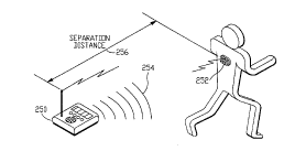
Figures 7 - 10 are pictorial illustrations of alternative embo-limente of the personal
10 alarm system of the present invention. Fig. 7 illustrates a base station 250 in two-way radio
communication with a remote unit 252 worn by a child. The child is running away from the
base station 250 such that the separation distance 256 has exceeded the preset threshold. The
base station has determined that an alarm should be given, and an audible ala~n 254 is being
sounded to alert a responsible caretaker. Fig. 8 illustrates a remote unit worn at the waist of a
15 workman whose location and safety are being monitored. Fig. 9 illustrates a mobile base
station 270 equipped with a cigarette lighter adapter 272 for operation in a vehicle. Fig. 10
illustrates a base station 280 adapted for operation from ordinary household current 282.
Fig. l l is a block diagram which illustrates a man-over-board system in accordance
with one aspect of the present invention, and ~le~eign~ted generally by the numeral 300.
The man-over-board system 300 includes a remote unit 302, having a navigational
receiver 304 and ~ntPnn~ 306 for receiving navigational information, a sensor 308, having an
output signal 310J a m~nll~lly operated switch 312, a radio transmitter 314 having an ~ntenn~
316. The man-over-board system 300 also includes a base station 318 having a radio receiver
320 connected to an ~ntPnn~ 322 for receiving radio tr~nemiesions from the remote unit 302.
25 The base station 318 also includes a display 324 for displaying the navigational location of
the remote unit 302, a display 326 for displaying the status of the sensor 308, a circuit 328 for
COll~;llg the field strength of the received radio tr~nemieeion with a predetermined limit
330, and an alarm 332 which is activated when the received field strength 334 falls below the
value of the limit 330.
In use, the remote unit 302 is worn by a user and an alarm will be given if the user
falls over board and drifts too far from the boat. The navigational receiver 304 receives
CA 02202779 1997-04-1~
Wo 96/13819 PCrlUS~5113823
16
navigational information, as for example from global positioning satellites 336. The
navigational receiver 304 converts the navigational information into a location of the remote
unit 302 and outputs the location 338 to the radio transmitter 314 for tr~n.~mi.~.~ion to the base
station 318.
The sensor 308 provides an output signal 310 and defines a sensor status. The output
signal 310 is conn~ctecl to the radio tr~n~mitter 314 for transmitting the sensor status to the
base station 318.
The m~ml~lly operated switch 312 includes an output 340 which is connected to the
radio tr~n.~mitter 314 and permits the user to signal the base station 318 by operating the
10 switch 312. In a ~rt;lled embodiment, the m~nll~lly operated switch 312 defines a panic
button.
The radio receiver 320 provides three outputs, the received location 342 of the remote
unit 302, the received sensor status 344, and an output signal 334 proportional to the field
strength of the received radio tr~n~mi~ion. As described above with respect to Figs. 1-3, the
15 remote unit 302 and the base station 318 define a separation distance which is inversely
proportional to the received field strength. The colnp~;lor circuit 328 compares the received
field strength 334 with a predetermined limit 330 and produces an output signal 346 if the
sign of the comparison is negative, indicating that the field strength of the received signal is
less than the limit 330. If the user drifts beyond a separation distance from the boat defined
20 by the limit 330, the alarm 332 is activated to alert the user's companions, who can ~hen take
~plopliate action.
In heavy seas or poor visibility, the base station 318 displays the current location of
the remote unit 302 on a suitable display 324. This is done in some a~plol,liate coordinate
system, such as standard longitude and latitude. This feature permits the base station to
25 m~int~in contact with the man-over-board despite failure to m~int~in direct eye conlact.
Fig. 12 is a block diagram which illustrates a man-over-board system including a two-
way radio communication link and ~le~i~n~te~ generally by the numeral 350. The man-over-
board system 350 includes a remote unit 352 and a base station 354.
The remote unit 352 includes a navigational receiver 356, a radio tr~n~mitte1 358, a
30 circuit 360 for causing the radio transmitter 358 to transmit at a high power level, a radio
receiver 362, and circuits 364 for activating a beacon.
CA 02202779 1997-04-1~
Wo 96/13819 PCr/US95113823
17
The base station 354 includes a radio receiver 366, a radio tr~n~mitter 368, a display
370 for displaying the location of the remote unit 352, a compactor circuit 372, a
predet~rmined limit 374, an alarm 376, and control circuits 378 for activating the radio
tr~n.~mitter 368.
The navigational receiver 356 is connected to an ~nte.nn~ 380 for receiving
navigational information, such as from global positioning system satellites (not shown). The
receiver provides the location 382 of the remote unit 352 for radio tr~n~mi~ion to the base
station 354.
The remote unit radio transmitter 358 and radio receiver 362 are connected to an1 0 ~ntenn~ 384 for communication with the base station 354. The base station radio receiver
366 and radio tr~n~mitter 378 are connected to an ~nt~.nn~ 386 for communication with the
remote unit 352.
The base station radio receiver 366 provides two outputs, the location 388 of the
remote unit for display by the location display 370, and a signal 390 whose value is inversely
1 5 proportional to the field strength of the signal received by the radio receiver 366.
The received field strength signal 390 and the predetermined limit 374 are compared
by the comparitor circuit 372 to determine whether the remote unit 352 is separated from the
base station 354 by a distance greater than the predetermined limit 374. An alarm 376 is
given when the sepàration distance exceeds the limit.
The control circuits 378 are used to cause the radio transmitter 368 to send a control
signal to the remote unit 352 for selecting high-power remote unit radio tr~n~mi.~ion, or
activating a visual or audible beacon for use in locating the user in heavy seas or bad
visibility.
Fig. 13 is a block diagram which illustrates an invisible fence for monitoring amovable subject and (1ecign~ted generally by the numeral 400. The invisible fence 400
includes a remote unit 402 and a base station 404 in one-way radio communication.
The remote unit 402 includes a navigational receiver 406, a radio transmitter 408,
storage circuits 410 for storing information ~lefining a geographical region, a comparitor 412,
second storage circuits 414 for storing information clefinin~ a predetermined positional status,
an alarm 416, and a circuit 418 and having a pair of electrical contacts 420, 422 for providing
a mild electrical shock.
CA 02202779 1997-04-1~
WO 96/13819 PCT/US95/138~3
18
The base station 404 includes a radio receiver 424, a comparitor 426, storage circuits
428 for storing information defining a predetermined positional status, and an alarm 430.
In the embodiment illustrated in Fig. 13, the invisible fence 400 defines a
geographical region, for example the outer perimeter of a nursing home in which elderly
5 persons are cared for. If a particular patient tends to wander away from the facility, creating
an llml~ l burden upon the staff, the remote unit 402 is ~tt~ch.ocl to the patient's clothing. If
the patient wanders outside the defined perimeter, the base station 404 alerts the staff before
the patient has time to wander too far from the nursing home.
Other applications are keeping a pet inside the yard, and applying a mild electrical
1 0 shock to the pet if it wanders too close to a defined perimeter. Att~ching the remote unit 402
to a child and alerting the caregiver in the event the child strays from a permitted area.
Placing the remote unit around the ankle of a person on parole or probation and giving an
alarm if the parolee strays from a permitted area. The invisible fence can also be used to
monitor movement of in~nim~te objects whose locations may change as the result of theft.
1 5 The remote unit navigational receiver 406 provides the location 432 of the remote
unit. In a ~lefclled embodiment, the storage circuits 410 are implemented using ROM or
RAM, as for example within an embedded microprocessor. Consideration of Figs. 14- 16 is
useful to an understanding of how the invisible fence operates.
Figs. 14, 15 and 16 are pictorial diagrams illustrating boundaries used to define
geographical regions such as those used in a preferred embodiment of the invisible fence 400.
Fig. 14 shows a portion 440 of a city, including cross streets 442-454 and a defining
boundary 456. The boundary 456 divides the map 440 into two portions, one portion above
boundary 456, the other portion below.
Fig. 15 shows a portion 460 of a city, including cross streets (not numbered) and a
closed boundary 462 made up of intersecting line segments 464, 466, 468, 470, 472 and 474.
The boundary 462 divides the city map 460 into two subregions, one subregion defining an
area 490 wholly within the boundary 462, and the other subregion defining an area 492
outside the boundary 462.
Fig. 16 shows a geographical region 480 which includes subregions 482 and 484.
Subregion 482 is entirely surrounded by subregion 484, while subregion 484 is enclosed
within a pair of concentric closed boundaries 486 and 488.
CA 02202779 1997-04-1~
W O96113819 P~l-/u5~sll3823
19
The information which defines these geographical regions and boundaries is stored in
the storage circuits 410, and serve as one input to the comp~ritQr 412 (Fig. 13). The
colllp~ilol 412 also receives the location output 432 from the navigational receiver 406. The
co" ~p~ or 412 compares the location of the remote unit 402 with the defined geographical
5 region and defines a relationship between the location and the defined region which is
~lessed as a positional status. The col"~ or 412 also receives an input from the second
storage circuits 414. These circuits store information defining a pre~leterrnined positional
status.
Some examples will be useful in explaining how the positional status is used.
1 0 Referring to Fig. 14, remote unit locations 494 and 496 are illustrated as dots, one location
494 being above the boundary 456, the other location 496 being below the boundary.
For the first example, assume that the location 494 is "within a defined geographical
region," and that the location 496 is "outside the defined geographical region." Assume also
that the predetermine~l positional status is that "locations within the defined region are
1 5 acceptable." Next assume that the navigational receiver 406 reports the location 494 for the
remote unit. Then the colllp~iLol 412 will define a positional status that "the location of the
remote unit relative to the defined region is acceptable." This positional status will be
transmitted to the base station 404 and will not result in activation of the alarm 430.
For the next~example, assume that that the navigational receiver 406 reports thelocation of the remote unit to be the location 496, and that the other assumptions remain the
same. Then the comparitor 412 will define a positional status that "the location of the remote
unit relative to the defined region is not acceptable." This positional status will be
transmitted to the base station 404 and will result in activation of the alarm 430.
For the next example refer to Fig. 16 which includes three successive locations 498,
500 and 502, shown linked by a broken line, as for example by movement of the remote unit
- 402 from location 498 to location 500 to location 502. Assume that the area outside the
boundary 488 defines an "acceptable" subregion. Assume further that the area between the
boundaries 488 and 486 defines a "warning" subregion. Also assume that the area 482 inside
the boundary 486 defines a "prohibited" subregion. Finally, assume that the navigational
receiver 406 provides three successive locations 498, 500 and 502.
CA 02202779 1997-04-1~
WO 96/13819 PCI/US95/13823
In a plcrell~d embo-1iment and given these assumptions in the precetlin~ paragraph,
the C~ ;lor 412 will det~rmine that the location 498 is acceptable and will take no further
action. The comparitor 412 will determine that the location 500 is within the warning
subregion 484 and will activate the remote unit alarm 416 to warn the person whose
movements are being monitored that he has entered a warning zone. When the remote unit
402 arrives at the location 502, the comparitor 412 will determine that the remote unit has
entered a prohibited zone and will activate the mild electric shock circuit 418 which makes
contact with the skin of the monitored person through the electrical contacts 420, 422. The
positional status reported by the remote unit 402 for the successive locations 498, 500 and
1 0 502 is "acceptable," "warning given," and "enforcement necessary," respectively.
In another embodiment, no enforcement or warning are given by the remote unit 402.
Tn~tça~l, as when used to monitor the movements of children or elderly patients, the
positional status is tr~n~mitted to the base station 404. There it is compared with a stored
predetermined positional status and used to set an alarm 430 if the positional status is not
1 5 acceptable. The predetermined positional status is stored in storage circuits 428 and the
comparison is made by the comparitor 426.
The ~,lerelled embodiment for the storage and comparison circuits is the use of an
embedded microprocessor.
Fig. 17 is a block ~ gr~m illustrating a personal alarm system such as the invisible
fence of Fig. 13, and de~ign~t~d generally by the numeral 520. Personal alarm system 520
includes a remote unit 522 and a base station 524.
The remote urlit 522 includes a radio tr~n~mittçr 526 and a radio receiver 528
connected to a shared ~nt~nn~ 530. The base station 524 includes a radio receiver 532 and a
radio tr~n~mittçr 534 connected to a shared antenn~ 536 and defining a two-way
communication link with the remote unit 522.
In one pler~ d embodiment, the comrnunication link is direct between the respective
trans~ el~ 526, 534 and the corresponding receivers 528, 532. Other embotlimenl~ include
access to existing commercial and private communications networks for completing the
communication link between the remote unit 522 and the base station 524. Typical networks
include a cellular telephone network 538, a wireless communications network 540, and a
radio relay network 542.
CA 02202779 1997-04-1~
WO 96/1381g P~ 113823
21
Fig. 18 is a block diagram showing an t;l~vilo~ ent~l moniL )lillg system for use in
fixed locations, dçsign~teA generally by the numeral 550. The environment~l monilolillg
system 550 includes a remote unit 552 and a base station 554.
The remote unit 552 includes storage circuits 556 for storing information defining the
location of the remote unit 552, at least one sensor 558, a radio tr~n~mitter 560, and an
~nt~nn~ 562.
The base station 554 includes an ~nt~nn~ 564, a radio receiver 566, a display 568 for
displaying the location of the remote unit 552, a comparitor 570, storage circuits 572 for
storing information defining a predetermined sensor status, and an alarm 574.
1 0 The ellvilv~ lent~l monitoring system 550 is useful for applications in which the
remote unit 552 remains in a fixed location which can be loaded into the storage circuits 556
when the remote unit 552 is activated. Such applications would include use in forests for fire
perimeter monitoring in which the sensor 558 was a heat sensor, or in monitoring for oil spills
when attached to a fixed buoy and the sensor 558 detecting oil. Other useful applications
1 5 include any application in which the location is known at the time of activation and in which
some physical parameter is to be measured or detected, such as smoke, motion, and
mechanical stress. The ellvilo~ lental monitoring system 550 offers an alternative to pre-
assigned remote unit ID numbers, such as those used in the systems illustrated in Figs. 2 and
3.
The storage circuits 556 provide an output 576 defining the location of the remote unit
552. This output is connected to the radio tr~n~mitt~ r 560 for communication with the base
station 554. The sensor 558 provides an output signal 578 defining a sensor status. The
output signal is connected to the radio ~ er 560 for communication of the sensor status
to the base station 554.
The communications are received by the base station's radio receiver 566 which
- provides outputs representing both the location 580 of the remote unit 552 and the sensor
status 582. The location 580 is connected to the display 568 so that the location of the remote
unit 552 can be displayed. The comparitor 570 receives the sensor status 582 and the
information defining the predetermined sensor status which is stored in the storage circuits
572. If the colllpdli~or 570 dett-rminl?s that the sensor status indicates an alarm situation, it
activates the alarm 574 to alert a base station operator.
CA 02202779 1997-04-15
W O96/13819 PCTnUSg5/13823
22
Fig. 19 is a block diagram which illu~ Les an alternative embodiment of a personal
alarm system in which the remote unit transmits demodulated navigational and precise time-
of-day information to the base station, and the base station uses that information to compute
the location of the remote unit. This ~ltern~tive embodiment is clç~ign~t~(l generally by the
nllmer~l 600 and includes a remote unit 602 and a base station 604.
The remote unit 602 includes a navigational receiver 606, a demodulator circuit 608, a
precise time-of-day circuit 610, a sensor 612, and a radio tr~n~mitt~r 614.
The base station 604 includes a radio receiver 616, com~ul~lional circuits 618 for
co~ uling the location of the remote unit 602, a display 620 for displaying the computed
1 0 location, a second display (can be part of the first display) 622 for displaying a sensor status,
a colll~u~;lol 624, storage circuits 626 for storing information ~1efining a precletermined
sensor status, and an alarm 628.
In a pler~ d embodiment, the navigational receiver 606 receives navigational
information from global positioning system s~tellites (not shown). In this embodiment, the
1 5 raw navigational information is demodulated by the demodulator circuit 608 and the output of
the demodulator 608 is connected to the radio transmitter 614 for commllnic~tion to the base
station 604.
The precise time-of-day circuits 610 provide the time-of-day information needed to
compute the actual location of the remote unit based upon the demodulated navigational
inforrnation. In the case of GPS navigational information, geometric dillusion of precision
colll~ul~lions are done at the base station 604 to derive the actual location of the remote unit
602.
The sensor 612 provides an output signal defining a sensor status. The demodulated
navigational information, the precise time-of-day information and the sensor status are all
connected to the radio tr~n~mitter 614 for communication to the base station 604.
At the base station 604, the radio receiver 616 provides the navigational and precise
time-of-day information to the colllyul~lion circuits 618 for d~L~. "~ g the actual iocation.
In a l l~rt;"~d embodiment, the conll,ul~lion is made using an embedded microprocessor. The
computed location is displayed using the display 620.
The radio receiver 616 also provides the received sensor status which forms one input
to the colllpalilol 624. Stored information defining a predetermined sensor status is provides
CA 02202779 1997-04-1~
Wo 96/13819 PCT/US95/13823
23
by the storage circuits 626 as a second input to the co~ ~;lor 624. If the received sensor
status and the stored sensor status do not agree, the com~ilor 624 activates the alarm 628 to
alert the base station operator.
Fig. 20 is a block diagram which illustrates an ~ltçrn~tive embodiment of the invisible
5 fence system in which the base station col~l~ules the location of the remote unit, and in which
the fence definitions are stored at the base station rather than in the remote unit. The
~ltçrn~tive system is tlesi~n~ted generally by the numeral 650 and includes a remote unit 652
and a base station 654.
The remote unit 652 includes a navigational receiver 656, a demodulator circuit 658, a
1 0 precise time-of-day circuit 660, a radio transmitter 662, a radio receiver 664, a shared ~nt~nn~
666, and control status circuits 668.
The base station 654 includes a radio receiver 670, a radio tr~n~mitter 672, a shared
~ntçnn~ 674, co~ uul~lion circuits 676, storage circuits 678, second storage circuits 680, a
first comparitor 682, a second comparitor 684, a display 686, an alarm 688, and control
1 5 circuits 690.
The navigational receiver 656 provides raw navigational information 692 to the
demodulator circuit 658. The demodulator circuit 658 demodulates the raw navigational
information and provides demodulated navigational information 694 to the radio tr~n~mitter
662 for communication to the base station 654. The precise time-of-day circuit 660 provides
time-of-day information 696 to the radio tr~n~mitter 662 for colm~ullication to the base
station 654.
The base station radio receiver 670 provides received navigational information 698
and received time-of-day information 700 to the computation circuits 676 for conversion to
an actual location 702 of the remote unit 652. The storage circuits 678 store information
defining a geographical region.
The first comp~ritor 682 receives the location 702 and the region defining information
704 and provides a positional status 706, as described above with respect to Figs. 13-16.
The second storage circuits 680 store information 708 definin~ a pre.lçt~rmined
positional status. The second comparitor 684 receives the positional status 706 and the
pre~let~rmined positional status 708 and provides control output signals 710 based upon the
results of the positional status comparison. When the location 702 is within a defined
CA 02202779 1997-04-lS
W O96/13819 PCTrUS95113823
24
"w~~ g" or "restricted" zone, the second co~np~;lor 684 activates the alarm 688 and causes
the location 702 to be displayed by the display 686.
In one pl~rt;lled embodiment, the remote unit includes circuits 668 which provide a
means by which the base station 654 can warn the remote unit user or enforce a restriction, as
5 for example, by applying the mild electric shock of the embodiment shown in Fig. 13. The
second co~ , ;lor 684 uses a control signal 710 to activate the control circuits 690 to send a
command via the radio ll~l,~lllill~l 672 to the remote unit 652 for modifying the remote unit
control status. For example, if the remote unit location is within a restricted zone, the base
station 654 will command the remote unit 652 to provide an electric shock to enforce the
1 0 restriction.
While the foregoing detailed description has described several embotliment~ of the
personal alarm system in accordance with this invention, it is to be understood that the above
description is illu~lld~iv~; only and not limiting of the disclosed invention. Thus, the invention
is to be limited only by the claims as set forth below.