Note: Descriptions are shown in the official language in which they were submitted.
CA 02202817 1997-04-16
1007-198
MtTLTI-PLY INDUSTRIAL FABRIC HAVING
INTEGRAL JOINTING STRUCTURES
Field of the Invention
The present invention concerns multi-layer industrial
fabrics. It is particularly concerned with fabrics assembled
from a multiplicity of pieces, each of which is smaller than
the completed fabric, and in which a jointing means is
incorporated in the component pieces substantially in the plane
of the completed fabric. The invention allows for modification
of the dimensional properties of the fabric as it is assembled,
and reduces the time required for fabric manufacture.
In the following description of this invention, the
following six terms have the meaning indicated:
"segment" means a unit or piece from which the fabric is
assembled by engaging the jointing structures
"ply" means each material used in a segment; a segment may
include plies made from more than one material;
"layer" means the parts of a segment or segments
superposed one on the other and providing the two parts of an
interlocking joint;
"continuous" or "discontinuous" refer to the jointing
structures: a continuous jointing structure is one having a
significant length (eg a rib-and-slot arrangement), whilst a
discontinuous jointing structure is composed of a plurality of
individual structures (eg a hook-and-loop arrangement);
"plane of the fabric", refers to the location of the
assembled joints, which is within the fabric, between the faces
of the two superposed layers making up the joint, each of which
are substantially parallel to the outermost faces of the
fabric .
Thus the fabrics of this invention are potentially multi-
layer fabrics, assembled from potentially a plurality of
segments, each of which may include a plurality of plies.
1
CA 02202817 1997-04-16
Discussion of the Prior Art
The dimensions of fabrics which can be woven by
conventional methods are dictated by the limitations imposed
by the loom construction. The known manufacturing methods are
slow, and little or no flexibility is available to adjust or
change the dimensions or physical composition the fabric,
during production. Numerous attempts have been made to design
nonwoven and modular fabrics which may be assembled quickly,
and produced with relatively smaller equipment, such as the
following:
(1) Assembling fabrics from one or more nonwoven arrays
of yarns, webs or woven bands which are subsequently bonded,
needled or otherwise attached together to form a cohesive
structure; see US 3,097,413 (Draper, Jr.), GB 975,750 (Plate),
or US 4,781,967 (Legge et al.).
(2) Spiralling successive strips or layers of nonwoven,
woven or knitted textiles to form a fabric substrate, and
subsequently bonding these layers or strips together by
needling, sewing, welding or the like to create the finished
fabric; see US 5, 268, 076 (Best et al . ) or US 5, 360, 656 (Rexfelt
et al . ) .
(3) Assembling a fabric from preformed interlocking
elements interconnected by complementary geometric shapes; see
US 4,842,905 (Stech) or DE 3,735,709 (Halker).
A disadvantage common to all of these known methods is
that the precursor fabric as it is assembled from its
components lacks structural integrity due to a lack of cohesion
between its constituent parts . Such a delicate fabric can only
be handled with great care, and cannot be installed on the
machine for which it is intended until it has been subjected
to a secondary process, such as needling, sewing, or another
bonding process. For example, when only lateral edge faces are
used for the alignment with adjacent edges of a spiral strip,
as in US 5,360,656, the precise alignment necessary to provide
a secure joint between them is difficult to attain. If the
2
CA 02202817 1997-04-16
joint is made by gluing, melting together or welding, the
strength of the resulting joint is limited by the strength of
the adhesive, the available surface area of the lateral edge
faces used, and the strength of the weld. If the joint is
sewn, the joint strength will be limited by the strength of the
sewing thread, and the ease with which the thread may be pulled
out of the fabric at that point.
Other methods, such as overlapping successive pieces,
usually require a time-consuming and expensive secondary
process to attach the pieces together to provide a cohesive
structure. In some cases, the overlapping can introduce
discontinuities that create difficulties in using the finished
product. Further, gluing, sewing, welding or melt joining can
disrupt the uniformity of the assembled fabric, again creating
difficulties in using the finished product, and the properties
of the adhesive or the sewing yarn used in the joint must be
compatible with the end use of the assembled fabric.
In some cases, it is desirable to have the ability to
seam, or make the final assembly, of the fabric on the
apparatus for which it is intended. If secondary processes
such as needling, sewing or gluing are required to do this,
their applicability will be limited by the space and precision
available at the apparatus, as well as the time available for
assembly. It is not possible to make an on-machine seam in a
paper making machine press section felt by needling the
opposing ends together in the press section. The applicability
of processes such as gluing or sewing for on-machine assembly
are also limited, due to the precision required, the available
working space, and the time available to install the fabric.
In some applications pin seams are used, but since a pin seam
introduces a discontinuity their use is limited. If a seam is
not created with sufficient care the seamed fabric can be
unacceptable for its intended purpose.
3
CA 02202817 2006-02-08
Summary of the Invention
The present invention seeks to provide an industrial fabric
that overcomes these difficulties. The industrial fabric of
this invention is assembled from at least one segment. The, or
each, segment has integral jointing structures incorporated into
at least one ply at selected locations, and which are
continuous, or discontinuous. The jointing structures engage
with, and interlock with, each other to provide a secure mating
engagement at selected locations on the segment, or segments,
making up the fabric.
The planar surfaces forming the joints are in the plane of
the finished fabric, and thus are not edge-to-edge joints. The
fabric structure is assembled by interlocking together as many
segments as are needed, to provide the required finished
industrial fabric, and the same jointing structures may be used
for final assembly of the fabric onto a machine. When at least
two segments axe incorporated into the fabric, each segment may
be identical, or segments having differing physical properties
may be used. The interlocked joint provides the fabric with
more than adequate cohesion as it is assembled, without
requiring any secondary processing. In some industrial
applications this cohesion facilitates secondary processing,
such as the needling of a nonwoven batt to at least one surface.
In the present invention by incorporating jointing structures
into the cooperating surfaces of the segments, a positive and
strong joint can be obtained between the segments in one
process.
This invention seeks to provide an industrial fabric comprising
at least one segment including at least one ply, wherein in the
fabric:
4
CA 02202817 2006-02-08
(a) the, or each, segment includes, in at least one face
which is substantially parallel to the plane of the
fabric, a ply including integral jointing structures
incorporated into the ply at selected locations of the
face of the segment; and
(b) the jointing structures incorporated into the or each
ply comprise formed structures which engage with, and
interlock with, each other to provide a joint between the
selected locations.
In a first broad embodiment, this invention seeks to
provide an industrial fabric comprising at least one first and
one second segment, each segment including at least one ply,
wherein:
(a) the or each first segment includes, in at least one
face which is substantially parallel to the plane of the
fabric, a first ply including first integral jointing
structures incorporated into the first ply substantially
parallel to the plane of the fabric at selected locations
of the face of the first segment;
(b) the or each second segment includes, in at least one
face which is substantially parallel to the plane of the
fabric, a second ply including second integral jointing
structures incorporated into the second ply substantially
parallel to the plane of the fabric at selected locations
of the face of the second segment; and
(c) the first jointing structure incorporated into the or
each first ply included in the first segment and the second
jointing structure included into the or each second ply
included in the second segment each comprise formed
structures which engage with, and interlock with, each
other to provide a lap joint between the selected
locations.
CA 02202817 2006-02-08
In a second more limited embodiment, this invention seeks
to provide an industrial fabric Comprising at least one segment
including at least one ply, wherein in the fabric:
(a) the, or each, segment includes, in at least one face
which is substantially parallel to the plane of the
fabric, a woven ply including integral jointing structures
woven into the ply at selected locations of the face of
the segment; and
(b) the jointing structures woven into the or each woven
ply comprise shaped yarns which engage with, and interlock
with, each other to provide a joint between the selected
locations.
In a third more limited embodiment, this invention seeks to
provide an industrial fabric comprising at least one segment
including at least one ply, wherein in the fabric:
(a) the, or each, segment includes, in at least one face
which is substantially parallel to the plane of the
fabric, a nonwoven ply including integral jointing
structures incorporated into the ply at selected locations
of the face of the segment; and
(b) the jointing structures incorporated into the or each
nonwoven ply comprise shaped structures which engage with,
and interlock with, each other to provide a joint between
the selected locations.
In a fourth more limited embodiment, this invention seeks
to provide an industrial fabric comprising at least two segments
including at least a first segment including at least
5a
CA 02202817 1997-04-16
one woven ply, and at least a second segment including at least
one nonwoven ply, wherein in the fabric:
(a) the, or each, first segment includes, in at least
one face which is substantially parallel to the plane of
the fabric, a woven ply including integral jointing
structures woven into the ply at selected locations of
the face of the segment;
(b) the, or each, second segment includes, in at least
one face which is substantially parallel to the plane of
the fabric, a nonwoven ply including integral jointing
structures incorporated into the ply at selected
locations of the face of the segment; and
(c) the jointing structures incorporated into the, or
each, segment ply comprise shaped structures which engage
with, and interlock with, each other to provide a joint
between the selected locations.
Preferably, the segments are chosen from at least one
member from the group consisting of: at least one single ply
continuous strip, at least one multi-ply continuous strip, at
least two different single ply continuous strips, at least two
different multi-ply continuous strips, at least one single ply
panel, at least one multi-ply panel, at least two different
single ply panels, and at least two different multi-ply panels .
Preferably, where a ply including the jointing structures
is a woven ply, the jointing structures are incorporated into
the ply at the selected locations during the weaving process
as a portion of either the warp or the weft yarns. More
preferably, in such a woven ply the integral jointing
structures comprise a portion of the warp yarns.
Preferably, where a ply including the jointing structures
is a nonwoven ply, the jointing structures are incorporated
into the ply at the selected locations during the process of
6
CA 02202817 1997-04-16
making the ply. Conveniently, such a nonwoven ply is made by
a process such as moulding, extrusion and thermoforming.
Preferably, where a segment includes at least one woven
ply, the or each woven ply is woven by a flat weaving process.
Preferably, the integral jointing structures are
discontinuous within the selected location on a ply, and are
selected from the group consisting of hook structures, loop
structures, hook and loop structures, and mushroom type
hermaphroditic structures.
Preferably, the integral jointing structures are
continuous within the selected location on a ply, and are
selected from the group consisting of slot-and-rib structures.
Preferably, where the assembled fabric includes both woven
and nonwoven plies the jointing structures are interlocking
slot-and-rib structures.
Preferably, where the assembled fabric includes only
nonwoven plies, the jointing structures are selected from the
group consisting of hook-and-loop structures, mushroom type
hermaphroditic structures and slot-and-rib structures.
Preferably, the segments include one or more plies having
a discontinuous jointing structure over at least one face.
More preferably, the segments include one or more plies
comprising a hook-and-loop type woven or nonwoven material,
similar to that known as Velcro (Registered trade mark of
Velcro Industries B.V.), in which the hooks and loops are
oriented in a more or less perpendicular direction to the plane
of the material. Preferably, each segment joint comprises in
combination at least one ply having hooks therein interlocked
with at least one ply having loops therein. Alternatively, the
segments include one or more plies having mating mushroom type
7
CA 02202817 1997-04-16
hermaphroditic structures such as those described by Melbye et
al in US 5,077,870. In a first option, each segment joint
comprises at least one first ply having hooks therein
interlocked with at least one second ply having hooks therein.
In a second option, each segment joint comprises at least one
first ply having both hooks and loops therein, interlocked with
at least one second ply having both hooks and loops therein.
In a third option, each segment joint comprises at least one
first ply having mushroom type structures therein interlocked
with at least one second ply having loops therein. In a fourth
option, each segment joint comprises at least one first ply
having mushroom type structures therein interlocked with at
least one second ply having mushroom structures therein.
The integral jointing structures may be located in only
a portion of one, or both, of the planar surfaces of the
segment; for example, in the margins of the segment.
Alternatively, the jointing structures may be located at
regular intervals over one entire planar surface of a segment,
so that interlocking takes place over substantially the entire
face area of each segment. It is also possible to locate the
jointing structures at regular intervals over both planar
surfaces of the segments.
The plies used in a segment, both woven and nonwoven, are
chosen to suit the end use of the fabric. Examples of nonwoven
ply materials include felt, fibrous materials such as batt
fibres, elastomeric foam in sheet form, film, and melt blown,
spun laced or hydroentangled fibres, moulded structures,
reaction extruded structures, thermoformed structures, and the
like.
Preferably, the industrial fabric structures of this
invention are assembled by applying a spiral winding method
similar to that disclosed in US 5,268,076 or US 5,360,656, to
a segment in the form of a continuous strip. Preferably, when
8
CA 02202817 1997-04-16
the fabric is created by the spiral winding method using at
least two offset segments each in the form of a continuous
strip, the width relationship of the two segments is n:l, in
which n is 1, or an integer.
The use of two strip segments, particularly segments with
their jointing structures located in offset edges, overcomes
in an elegantly simple fashion one of the chief difficulties
with the spiral method as no special steps have to be taken to
bond the strip edges together to ensure lateral strength and
stability in the two layer fabric, and there are no problems
with any unevenness in the strip edge area as a result of using
special methods for jointing the strip segment edges together.
Due to the presence of two layers in the fabric, some minor
imperfections of edge alignment between successive turns in the
spiral can be tolerated. However, the edges of successive
turns should be kept in as close register with each other as
is possible.
When two, or more, segments in the form of strips are
used, the physical properties of each segment need not be the
same, and can be focussed on different requirements, such as
wearing properties, and structural strength.
Alternatively, for segments in the form of panels, it is
preferred that the segments be assembled in a piecewise fashion
so that the jointing structures on the separate segments are
interlocked sequentially to form the necessary joints.
If the chosen integral jointing structure is a slot-and-
rib type complementary mating structure, it can be obtained
either by using specially shaped yarns, or by forming the two
parts of the structure directly in a nonwoven segment.
Specially shaped yarns are woven into each segment as either
warp or weft . At least four arrangements of these slot-and-rib
integral jointing structures are possible.
9
CA 02202817 1997-04-16
In the first arrangement, two different segments are made,
so that one segment includes slots, and the other segment
includes ribs. The number and placement of the slots in one
segment, and of ribs in the other segment are preferably the
same, so that equal numbers of ribs and slots are used in the
joint.
In the second arrangement, only one type of segment is
made, and both slots and ribs are provided in the segment.
Because the ribs and slots of each segment are provided in the
same sequence, all segments are thus identical and the planar
surface of a first segment can be attached to the equivalent
planar surface of a second segment as in the first method. The
segments are positioned so that sufficient pairs of slots and
ribs are interlocked to provide a secure joint.
In the third arrangement, which appears to be only
applicable to woven segments, an offset weaving process is used
in which one ply of a two-ply segment is woven so that it is
offset to one side, and the second ply is woven so that it is
offset by an equal amount to the opposite side. The lateral
jointing area of each ply may contain either slots, or ribs,
or both slots and ribs. Adjacent segments can be interlocked
at their edges to produce a fabric with no dimensional
discontinuities . In this special case, the central part of the
segment is woven in a single step, and the two plies are
interconnected by tie strands interwoven between each of the
plies.
In the fourth arrangement what is effectively a variation
of offset weaving is used. A sequence of ribs and slots is
woven across the full width of one face of each ply. The two
plies are simultaneously woven with the desired offset in the
loom. The offset plies are interlocked as they are woven, by
passing the two plies through a roller nip at the loom take-up
roll which forces the slot and rib yarns into engagement to
CA 02202817 1997-04-16
form a two ply segment, with two laterally exposed jointing
areas.
The on-loom attachment of the plies to each other in the
segment can be further enhanced by means of so-called "tie
strands", which interlace both plies and aid in holding them
together. This serves to pull the plies together, and will
facilitate the engagement of the slot-and-rib yarns from both
plies. In-plane movement of the individual segments within the
assembled fabric is also minimized due to the strong and
positive attachment at the jointed surfaces, thereby further
reducing possible defects in the assembled fabric.
It is preferred that slot-and-rib yarns are woven in the
warp direction. If woven in the weft direction, special weft
insertion equipment will be required to prevent the weft yarns
from twisting about their longitudinal axes. The orientation
of the slot yarns must be controlled during weaving so that the
slot is always presented to the jointing surface of the
segment. One way to accomplish this is to make at least one
surface of the strand containing the slot or rib flat, or
nearly flat. This serves to define the orientation of the slot
during the weaving process and thus its orientation in the
segment after weaving.
It is necessary that the rib yarn is the right size to
engage and to interlock securely with the slot yarn. It is
also possible to use a hollow rib yarn for engagement with the
slot yarns, so that it can be deformed during interlocking.
This can be beneficial in that, as the rib strand is interlaced
and traverses the planar surface of the woven segment used for
attachment, the yarn can be oriented to be relatively narrow
in the plane of the jointing surface of the segment. When it
engages with a slot yarn it does not unduly distend the sides
of the engaging slot. However, once it is meshed into the
slot, it can be deformed thus creating a positive interlock.
11
CA 02202817 1997-04-16
To effect such a positive interlocking, the rib-and-slot
yarns must stand proud of the planar surfaces to be joined.
It is desirable to use a relatively long float of the rib and
slot yarns at the surfaces to be joined, so that maximum
continuous interlocking can be achieved. The length of the
float, and consequently the weave design of the segment, must
be balanced with the other properties required in the assembled
fabric.
If the chosen integral jointing structure of the segments
is a discontinuous one, such as hook-and-loop and mushroom type
complementary mating materials, in which the hooks and loops
may be yarns, then these materials are incorporated into the
segment as a ply, or part of a ply. It is possible to weave
a region containing a hook and loop structure along one edge,
or both edges, of a woven ply, and to weave a hook and loop
structure into a ply such that the hooks are located in one
planar surface, and the loops are located in the other. In a
multi-layer fabric the plies can be offset to one another, and
the hooks and loops are interlocked in the central portions.
Where the segments are nonwoven, there is a similar level
of flexibility. The chosen jointing structures are
incorporated into the desired locations on the plies during
manufacture, and then interlocked.
In certain instances it is possible to use a discontinuous
jointing structure interlocked with a continuous one, for
example a combination of a slot with a row of mushroom shapes.
In the descriptions that follow, the concepts described
for the sake of clarity in the context of a woven fabric
incorporating specially shaped yarns are equally applicable to
nonwoven fabrics in which the jointing structures are formed
as a part of the nonwoven fabric . A woven fabric hook-and-loop
structure has effectively the same jointing properties a
12
CA 02202817 1997-04-16
nonwoven fabric including integrally formed hook-and-loop
structures.
In addition to providing a secure joint, these hook and
loop materials provide a fabric which in the two layer joint
between plies includes a proportion of yarns more or less
permanently oriented perpendicularly to the plane of the
fabric. This has the unexpected result that more or less in
the middle of the fabric there is a region with significant
void volume. These perpendicular yarns tend to resist the
compaction of this void volume, which is a significant
advantage for example in a base fabric for a press felt in a
papermaking machine. The presence of the central void volume
will aid in extracting water from the wet paper web.
There are several arrangements of hook and loop materials
that can be used.
In a first arrangement, a layer of hook material is
interlocked with at least one layer of loop material. The
nature and inherent strength of the joint is determined by the
parameters chosen for the hooks and the loops, and by the
interlocked area of the joint.
In a second arrangement, a layer of hook material is
interlocked with at least one layer of hook material, and all
of the segments are then the same. For a woven ply this
arrangement has the disadvantage that a hook-to-hook joint is
not as mechanically strong as a hook-to-loop joint. The
strength of a hook-to-hook joint for both a woven and a
nonwoven ply can be improved by including a thin layer of batt
between the layers of hook material, and through which the
hooks of each layer of hook material are interlocked.
In a third arrangement, two layers of hook-and-loop
material are interlocked, each of which includes hooks and
13
CA 02202817 1997-04-16
loops. This arrangement has the advantages that all of the
segments are the same, and a reasonably strong joint is
obtained.
The spiral winding method of interconnecting two fabric
strip segments offers several advantages. As the fabric is
built up, lap type joints are formed between the jointing
structures. By using the surfaces of the segments to form the
joints, the joint mechanical strength is easily controllable,
and may be increased or decreased by adjusting the size of the
overlap. In the spiral winding method, almost any combination
of strip widths is feasible, provided that the edges of the two
strips are not located one above the other in the assembled
fabric. It is preferred that the widths of the strips be in
a ratio of n:l, in which n is either 1, and the strips are of
the same width, or n is an integral number. The strongest
joint will be obtained when the ratio of the strip widths is
1:1, and the strips overlap each other by 50~ of their width.
If strips are used whose widths are such that n is not an
integral multiple, then there is the possibility that the edges
of the two strips will coincide, and a discontinuity will occur
through the thickness of the fabric. At this discontinuity,
there will be no overlap, and thus no cohesion between the
strips to provide lateral strength in the fabric. This is not
desirable.
When a fabric is assembled by spiral winding separate
segments of either slot-and-rib or mushroom type structures,
each ply in the segment will have its own neutral bending
plane. In the completed fabric, the outer segment will have
a slightly greater length than the inner segment. Even though
there is a secure joint between the segments, the jointing
structures do allow the two layers to move a little relative
to each other to accommodate the effects of curvature.
14
CA 02202817 1997-04-16
This method for jointing segments together makes it
possible to assemble the fabric from segments of differing
properties, so as to create asymmetry through the plane of the
fabric. Asymmetry through the plane of the fabric is
advantageous for many reasons, for example, to manipulate the
neutral plane of the assembled fabric which can then be used
to minimize speed differences at the surfaces of the fabric due
to its thickness when running over rolls with differing radii.
The ability to define the surfaces of the assembled fabric by
means of asymmetry through the plane of the fabric is
beneficial in providing contact area differences between the
outer surfaces and surface contour differences which can be
useful for managing boundary layer air in moving fabrics.
By means of this invention, it is now possible to alter
easily the fabric segments independently of each other, so that
one outer surface can be optimized for one property and the
other outer surface optimized for a different property.
Further, the outermost plies of the segments need not be those
involved in making the segment to segment joints . For example,
by using different materials, abrasion resistance could be
optimized for one surface and contamination resistance the
other. Many alternatives are thus possible within the scope
of this invention.
By adjusting the inner surface area of each ply, the
strength of the joint can now be adjusted. Also, by keeping
the surface area of the joint constant but adjusting the
density of the jointing structures, such as hook-and-loop or
slot-and-rib, the strength of the joint can be adjusted. Since
the jointing structures are incorporated into the segments,
their placement can be precisely controlled thus making the
attachment to the adjacent segments accurate and easily
accomplished. The precise placement of the jointing structures
into each segment also reduces defects in the assembled fabric.
CA 02202817 1997-04-16
For some applications it is desirable to make the
interlocked joint between the jointing structures more secure.
When slot and rib structures are used an adhesive may be
placed in the slots. If an adhesive is used, its application
into the slots protects it during manufacture, whilst making
it available to provide adhesion in the joint when the two
jointing structures are interlocked. In some cases it is
possible to use a chemically reactive system instead of an
adhesive, such as a polyurethane: the reactive material itself
bonds the jointing structures together to form a bond whose
strength is equal to, or closely approaches, the strength of
the material used in the rib and slot structures.
Alternatively, it is sometimes possible to insert a layer of
nonwoven material between the plies, such as a thin layer of
fibrous batt between hook and loop, or hook and hook,
structures, or a web of hot melt adhesive.
By having the opportunity to assemble panels which have
defined length and width, a different level of flexibility is
achieved in the manufacturing process when compared to a strip
or strips.
Because the integral joints are precisely located in the
plies of individual segments, it is now possible to provide an
assembled fabric which can be finally joined on the machine for
which it is designed. For example, to form a closed loop, the
final joint or joints are the same as all of the others between
the segments.
By using the two layer overlapped joints of adjacent
segments as the means of closure, in which the joint is
substantially in the plane of the fabric, it is now possible
to make that closure in such a way as to make its orientation
with respect to the body of the fabric an optimum for the
specific performance required. As an example, the closure in
a paper machine press felt would not need to be in the cross
16
CA 02202817 1997-04-16
machine direction, i.e. perpendicular to the running direction
of the felt. This would remove the closure as a source of
vibration or bounce in the press section.
A further advantage inherent in this invention arises when
a rib and slot structure is used as the jointing structure.
Almost any pair of mating structures in which one element is
inserted into the other can be used, ranging from a simple
rounded rib fitting into a simple groove-like slot, to complex
structures such as dovetail shapes, in which both the rib and
the slot include a wedge shape, and shapes including one or
more barbs. The choice of the cooperating shapes for the rib
and the slot is determined by the ability to fabricate them
reliably in the desired locations, by the strength required in
the assembled joint, and by the ability to assemble, and, if
required, to disassemble the joint.
For applications in which either continuous or
discontinuous jointing structures are used and which will only
be separated when the whole fabric is replaced damage to the
structures on separation is immaterial. On the other hand, if
it is required to be able to open and to reclose the joint, or
to be able to replace a part of the fabric, then jointing
structure damage on opening the joint is not acceptable.
This invention also provides a solution to one problem
associated with extended nip press belts, also known as press
blankets . These belts are required to have a smooth inside
surface, which is obtained by applying a grinding process to
the inside face of the belt prior to use. This grinding step
is complicated by the fact that these belts are often
impregnated with, or encased in, a polyurethane material, which
is intended to make the belt impervious to roll lubricating
oil. The presence of the coating makes it effectively
impossible to turn the belt inside out for grinding. Typical
examples of this type of belt are described by Stigberg, in US
17
CA 02202817 1997-04-16
5,171,389 and in US 5,196,092; by Dutt in US 5,238,537; by
Schon in US 5,132,141; by Jermo in US 5,525,194; by Watanabe
et al in CA 2,065,903; and by Matuschczyk in CA 2,068,800. By
using the fabrics of this invention it is possible to assemble
such belts from segments that are ground to exact dimensions
before assembly.
This invention also makes it possible to make fabrics in
which one side has a predetermined pattern such as grooves or
other surface structures. For example, a fabric with mushroom
type fasteners can be attached to a perforated roll, and a
ribbed fabric can be located onto a slotted roll surface.
These fabrics facilitate roll maintenance because the old cover
can be removed and a new cover installed without dismounting
the roll.
Brief Description of the Drawings
The invention will now be described by way of reference
to the drawings in which:
Figures 1, 2 and 3 illustrate multi-ply fabric structures
including three different arrangements of slot-and-rib jointing
structures;
Figures 4 through 15 are cross sectional illustrations of
various slot-and-rib combinations;
Figures 16 and 17 depict two seam constructions using the slot-
and-rib jointing structures;
Figures 18 and 19 illustrate hook-and-loop and hook-and-hook
yarns as the integral jointing structures;
Figure 20 illustrates fabric assembly of strip segments by the
spiral winding process;
Figure 21 illustrates offset weaving with the addition of tie
strands to further secure the fabric plies together;
Figure 22 illustrates a further slot-and-rib combination;
Figures 23 and 24 illustrate moulded plies using the slot-and-
rib combination of Figure 16;
18
CA 02202817 1997-04-16
Figure 25 illustrates a mould used to make the plies of Figure
24;
Figure 26 illustrates a fabric including two extruded hook-and-
hook structures; and
Figure 27 illustrates a slot-and-rib combination including a
channel for an insert.
Detailed Description of the Drawincrs
In the Figures the symbol 1 represents a rib structure,
the symbol ~ represents a slot structure, and the symbol
represents an ordinary yarn. In Figures 18 and 19 the symbol
n represents a loop, and the symbol T represents a hook.
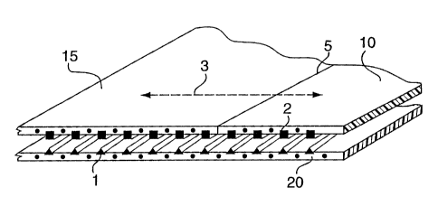
Figure 1 shows schematically a cross section in the
direction 3 of three segments 10, 15 and 20, into which slot
structures 1 and rib structures 2, generally designated as "S"
and "R" hereafter, are the jointing structures; these may be
either woven or nonwoven plies. If any of 10, 15, and 20 are
woven structures, the S and/or R structures are incorporated
during the weaving process, and the ply is woven according to
a weave design which provides for long exposed floats of the
yarns including the R and S structures, to facilitate their
engagement and interlocking. In the area of the fabric shown
(see also Figure 2) all three segments are involved in the
joint. Segments 10 and 15 are not jointed to each other, but
rather abut each other closely along the line 5. However both
of segments 10 and 15 are jointed to the segment 20, which
overlaps the joint line 5 between segments 10 and 15.
In this embodiment, all of the jointing structures 1 in
segments 10 and 15 are S, and all of the jointing structures
2 in segment 20 are R yarns. As Figure 1 shows, if woven plies
are used, it is not necessary that all of the yarns of the
segments to be joined be R and S yarns . The invention may also
be practiced by incorporating two, three, or more ordinary
yarns in between R or S yarns: the spacing required for the R
19
CA 02202817 1997-04-16
and S yarns is determined by the properties desired in the
assembled fabric. For a woven ply, the size, type (e. g.
monofilament, spun yarn, braided yarn etc), and composition of
the ordinary yarns, and the composition of the R and S yarns,
are also determined by the properties of the assembled fabric.
To assemble the finished fabric, the segments are brought
into alignment so that the S structures in segments 10 and 15
are brought into engagement with the R structures in segment
20. The two segments are then interlocked by pressing the ribs
into the slots, thereby forming the desired joints. For woven
plies, if the direction 3 corresponds to the wefts, and the R
and S yarns are therefore both warp yarns, the interlocking of
the segments 10 and 15 with segment 20 is conveniently obtained
by passing the engaged segments through a roll nip.
Alternatively the segments 10 and 20 may be pressed into
engagement and interlocked by hand or by any suitable pressure
means.
In Figure 2 the R and S structures alternate, and segments
10, 15 and 20 have the same pattern. Since one segment must
be inverted relative to the other to form a joint - the two
sides marked as A will have been on the same side during
segment construction - the pattern in the inverted segment
becomes a mirror image of the other, and the three segments can
be interlocked. The segments 10 and 15 are again in a closely
abutting relationship along the joint line 5.
It is not necessary that the R and S structures 1 and 2
extend for the full width of the segment. For some
applications the R and S structures need only be provided in
the lateral margins of the fabric segments, as is illustrated
schematically in Figure 3, where the area 4 does not contain
any jointing structures. Consequently, in the area 4 the two
plies are not connected together at all. This arrangement is
suitable for constructing both a two layer fabric in which each
CA 02202817 1997-04-16
segment is of the same size as the fabric, and a two layer ply.
This arrangement is also suitable in instances where a batt is
attached to the fabric, and the needling process will provide
sufficient attachment between the fabric segments remote from
the two layers in the joint area.
When the segments shown in Figure 3 are assembled into a
fabric it is not necessary that the two ply faces be engaged
as shown, with the edges X and Y in registration. The segment
can be offset relative to the segment 20, so that the edges
X and Y are not in registration. If the construction used in
Figure 3 is offset, the widths of the two jointing areas at
each edge of the segment will generally not be the same, but
the pattern of R and S structures in the two segments can
continue to be the same.
Yet another alternative is shown in the cross section in
Figure 21. In applications where it is not necessary that the
joint extend over the full face area of the ply or segment an
offset construction can be used, for example by using offset
weaving of two plies A and B in a single segment. The S and
R structures 1 and 2 are only provided in the relatively
thinner offset regions 6, so that when the fabric is assembled
it has a constant thickness . In the inner area 7 the two parts
A and B of the two ply weave are joined together by ties or
binder yarns, as at 16. As shown, the segment has a flattened
Z section; it can also be made as a flattened T section, in
which case alternate segments are inverted on assembly.
There are a great many possible combinations of R and S
structures which may be used in forming the joints between
segments . A selection of some of the possible shapes are shown
in the cross-sections of Figures 4 through 15, and in Figure
22. In these Figures, for clarity, these structures are shown
as yarn cross sections. With the exception of Figure 8, which
is discussed below, the remainder can all be made as part of
21
CA 02202817 1997-04-16
a nonwoven sheet material, for example by well known plastic
extrusion methods. It is also contemplated that combinations
may be made in which one of the R and S structures is a yarn,
and the other is not.
There appear to be only two limitations on the shapes of
these structures: the ability to create each member of the
pair (by extrusion or other suitable forming process) of
suitable dimensions in a suitable plastic material; and the
ability to engage and to interlock them to form a fabric. When
these structures are used in the form of a monofilament yarn
there is a third limitation: the ability to incorporate the
yarn into a woven ply with the yarn correctly oriented. In all
of these Figures, except perhaps Figures 8, 14 and 15, the
upper section is the R structure, and the lower section is the
S structure. In Figure 8 the R structure is a deformable
hollow yarn rather than one with a protruding shaped rib, which
is deformed upon interlocking into the slot in the S structure,
which need not be another yarn. In Figures 14 and 15 each of
the structures include both a slot and a rib; as shown ghosted,
these structures can be easily extended laterally into the form
of a ribbon or sheet.
The major mechanical requirement of any these shaped
structures is that they provide secure and positive
interlocking. This is done by ensuring that the rib is a
secure fit into the slot, and for many of these shapes the rib
is conveniently somewhat larger in cross section than the slot
into which it is interlocked. It is also possible to provide
some free space in a slot-and-rib combination, as shown in
Figure 27. The free spaces 80, 81 can be used for several
purposes: space 80 can contain an adhesive, or a chemically
reactive system, and space 81 is suitable for a reinforcing
fibre. These spaces can also be left empty to provide a
channel for fluid flow laterally within the finished fabric or
to provide some resiliency in the fabric.
22
CA 02202817 2006-02-08
A key feature of this invention concerns the jointing of the
segments by means of a lap type joint, using at least a part of
the planar surfaces of adjacent segments. Such a joint is
illustrated in Figures 16 and 17, which show two woven plies
incorporating two different arrangements of R and S yarns: fabric
segments l0 and 20 are jointed together by overlapping the
regions 11 and 21. Each of the segments may be composed of two
plies as at 12 and 13 in segment 10, and at 22 and 23 in segment
20. In this form of construction it is preferred that each
segment is a composite fabric, in which the two woven structures
comprising the two plies are offset to provide the jointing
areas. To assemble the fabric, the R and S yarns 1 and 2 woven
into the regions 11 and 21 are brought into engagement, and then
pressed to interlock them. The same principles also apply to
formed structures.
The difference between Figures 16 and 17 is the orientation
of the R and S yarns. In Figure 16, the R and S yarns are
oriented along the length of the segment; in a composite fabric
they would be warp yarns; in an assembled fabric which is used as
a moving continuous loop, such as a papermaking machine dryer
fabric, these warp yarns are usually arranged parallel to the
direction of movement, or machine direction, of the fabric. With
this orientation the resulting joint will be relatively weak, and
will not withstand significant tensile stress across the joint.
Such a joint is therefore only suitable for relatively low stress
applications. The cohesion of such a joint can be improved by
placing an adhesive or reactive system in the S structures, as
discussed above in the context of Figure 27.
In Figure 17 the R and S yarns are oriented across the length of
the segment; in a composite fabric they would be weft yarns, and
be oriented in the cross machine direction in a moving continuous
loop fabric. This provides a considerably stronger joint, and
the cohesion of this joint also can be easily increased by
23
CA 02202817 2006-02-08
application of a suitable adhesive or reactive system in the
slots of the slot-type yarns prior to engaging the rib yarns.
In Figures 18 and 29 there are shown cross sections along
the direction 3 of two segments 30 and 40 in which a hook-and-
loop arrangement is used to provide the integral jointing
structures. Methods of weaving both hook, loop, and mixed hook
and loop fabrics are well known (see, for example, Brabander, US
3,943,981; Higashinaka, US 5,369,852; and Okawa, US 5,369,853).
It is also known to make the same structures as plastic
extrusions. In the construction of these materials it is
possible to control the relative lengths of both hooks and loops,
the density of hooks and loops in unit area of the ply joint
area, and to provide hooks, loops, or a mixture of hooks and
loops in the finished ply. The manner in which these choices are
made largely determines the properties of the joint made when the
plies are interlocked. When the two segments 30 and 40 are
pressed together, the hooks and loops interlock to hold the
material securely. As is well known in this art, both of plies
30 and 40 can be the same, and include both hooks and loops. Two
jointing areas which include collectively both hooks and loops
provide the best joint; the use of mixed hooks and loops in both
jointing areas has the advantage that the segments can all be the
same. In Figure 18 ply 30 includes only hooks as at 31, and ply
40 the includes only loops, as at 41.
It is also possible to obtain segments that are all the same
by using only hooks in the jointing area, as is shown in Figure
19. The degree of adhesion obtained with a hooks only joint is
lower than with a combination of hooks and loops, and
consequently such a joint is only suitable for relatively low
stress applications. The cohesion of such a joint can be
improved, by inserting a thin layer of batt, as shown ghosted
at 41, in between the two hook areas before pressing them
24
CA 02202817 1997-04-16
together. In contrast, in a nonwoven segment including
mushroom type jointing structures, the resulting joint usually
has more strength than a hook-and-loop one even though all the
discontinuous jointing structures are the same.
It has been noted above that the fabrics can be assembled
by a modified form of the spiral winding method. This is shown
in Figure 20. In the original spiral winding method, as
described in US 5,268,076 and US 5,360,656, a strip of fabric
101 from a reel 102 is wound under some tension and at a small
angle around a pair of rollers 103 and 104. The rollers are
so spaced that the resulting fabric is of the desired
circumference to fit the location for which it is being made,
such as the press section of a papermaking machines if
required, more than two rollers can be used. Due to the fact
that the fabric strip is at a small angle to the rollers, the
strip is wound in a spiral. As described in US 5,268,076, the
location of the fabric reel 102 is fixed, and the spiral of
fabric built up on the rollers is moved sideways along the
rollers, in the direction 100 as it is formed. This method can
be improved by moving the reel rather than the spiral turns on
the rollers: as the fabric strip unwinds in the direction of
the arrow 105 the reel 102 is moved sideways in the direction
of the arrow 106. In each case, the spiral turns are arranged
in a closely abutting relationship.
One difficulty with this method is the linear edge joint
between successive turns of fabric in the wound spiral. If the
successive turns of the spiral are to have any lateral cohesion
this joint must be as complete and as robust as is possible.
Further, the manner of creation of this edge to edge joint must
not be such as to introduce disconformities into the spiral
fabric . For example, this method is recommended for making the
base fabric for a papermaking machine press felt: any
disconformity in this edge-to-edge joint will likely result in
different water removal characteristics in the joint area,
CA 02202817 1997-04-16
which will cause an unacceptable level of marking of the wet
paper web in the press section. The creation of this edge-to-
edge joint between the adjacent edges of the successive spiral
turns is a major problem with the spiral winding method.
The present invention provides an elegant and simple
solution to this problem, especially for a fabric comprising
at least two segments which are both strips. The first strip
is wound onto the rollers more or less as described above. At
the same time, the second strip segment 112, as is shown in
chain line in Figure 20, from a second reel 113 is wound at the
same small angle on top of the first segment 101 around the
rollers 103 and 104. As the second segment unwinds in the
direction of the arrow 114 the second reel moves sideways in
the direction of the arrow 115, and the second segment 112 is
wound in a matching spiral on top of the first segment 101.
If desired a third segment can be wound onto the spiral from
another reel assembly.
As shown, the segments 101 and 112 are of the same width,
and the reels 102 and 113 are arranged so that the segment 112
is offset by half of the width of segment 101. This
arrangement will provide the strongest joint. Since the two
segments are wound onto the rollers 103 and 104 under some
tension, with the jointing structures facing each other, as the
second segment 112 is wound on overlaying segment 101 the
jointing structures engage and to a degree interlock with each
other. For segments using hook and loop joints this level of
tension is often sufficient; for rib and slot joints it may be
necessary to provide a further pressure roll, for example
adjacent roll 104. Further, since the two segments are
laterally offset, the second segment 112, as at the area 116,
engages with both of the two lateral edges 117 and 118 of the
segment 101. This provides a spiral wound fabric with more
than enough cohesion between the successive turns of the spiral
to permit it to be handled.
26
CA 02202817 2006-02-08
If segments of differing widths are used in this modified
spiral winding method, the same constraints apply to the
relative widths of the fabric. If the ratio a between is
other than an integral number, then there is the possibility
that the overlap area will steadily decrease, until a point
will arise at which the edges of the two segments do not
overlap. This can only be tolerated if the fabric is so
narrow that not enough turns are present in the spiral for
such a discontinuity to occur in the fabric; the fabric spiral
should be wound so that no discontinuity extends right through
the thickness of the fabric.
The spiral winding method is also suitable for use with a
single segment strip that has the jointing areas offset at its
edges, as shown in Figure 21.
In Figure 22 is shown a further slot-and-rib combination
similar to that shown in Figures 4 - 7, in which the dovetail
system is separated into two parts. One part may be inverted
relative to the other as at 51 and 52, or the two parts may be
the same way up, as at 52 and 53.
Figure 16 illustrates a slot-and-rib combination for a
pair of yarns: the same jointing structure can be used in a
moulded ply, and is illustrated in Figures 23 and 24. In
Figure 23 one ply 60 includes only S structures, and the other
ply 61 only R structures, whereas in Figure 24 both plies 62,
63 are the same, and include both S and R structures . These
Figures also show a further feature of this invention, namely
that a ply need not be continuous: the segment in these
Figures includes spaces 64, Figure 25 illustrates a mould
suitable for making the plies in Figure 24.
Figure 26 illustrates two forms of an extruded hook-and-hook
structure. The double hooks 70 on ply 71 are not the same
27
CA 02202817 1997-04-16
shape as the double hooks 72 on ply 73. Each shape can also
be interlocked with itself.
In addition to the above noted benefits, novel properties
can now be engineered into the fabric by employing differing
materials in each ply. For example, it would be possible to
assemble a multi-ply fabric structure from several plies each
having a different porosity, some of which may even include
void spaces, a feature which would be useful in filtration
applications. Alternatively, one or more plies could be made
impermeable, for example by using a nonwoven moulded or
extruded ply, and provided with reinforcing yarns in at least
the running direction, the final fabric structure being useful
for transport belting or in pressing applications, such as shoe
presses. An additional possibility is that by using different
constructions in each of the plies, it would be possible to
affect the neutral line of the fabric, which affects the
flexibility of the assembled fabric. The interlocking jointing
structures of the segments also provide further opportunity to
develop unique mechanical properties in the fabric, such as
compressive strength and interior void volume.
This lap type joint provides the fabrics of this invention
with several important advantages over similar so-called
modular fabrics of the prior art. Firstly, by using surfaces
of ,the individual plies substantially in the plane of the
fabric to form the joint, rather than a thin ply edge
substantially vertical to the plane of the fabric, the
mechanical strength of the finished fabric is easily
controllable. Secondly, by overlapping adjacent segments,
control of their relative placement into a closely abutting
relationship is easier to accomplish, thereby providing more
consistent and relatively defect free joints. Thirdly, any
defects which may occur during manufacture in one ply may be
at least partially hidden by the other ply used in the lap type
joint, and therefore may not create an unacceptable
28
CA 02202817 1997-04-16
discontinuity in the fabric. Fourthly, because the fabrics of
this invention are assembled from plies and segments which can
be manufactured ahead of time and will basically snap together,
production and manufacturing scheduling can be reduced in
complexity, and manufacturing time shortened. In addition, the
machinery required to produce industrial fabric structures
according to the invention need not be as large (wide) as has
been required when conventional fabrics are produced as a whole
unit. The fabric structures of the present invention thus
represent cost savings in both capital equipment expenditures
and manufacturing time.
Yet a further advantage offered by this invention relates
to the installation of these fabrics onto the equipment for
which they have been manufactured, such as the forming, press
or dryer section of a paper machine. The method by which the
segments are assembled to produce the final fabric structure
may also be used to provide an on-machine seam or joint to
attach the distal ends of the fabric together to render it
endless, and to provide the required continuous loop. The
final joint closing the loop does not have to be linear across
the fabric, as is the case for example with a pin seam, or in
a specific orientation in relation to the edges of the fabric
structure. Such a seam is non-marking and capable of
withstanding the rigours of use in the papermaking machine.
29