Note: Descriptions are shown in the official language in which they were submitted.
;- CA 02203111 1997-04-18
VJO 96f12861 PCTIfIS95/13255
METHOD AND APPARATUS FOR EXTENDING A FRAME
FIELD OF THE INVENTION ~ - _
. The present invention relates to fastening methods
and apparatus and more particularly, to-a method and
apparatus suitable for extending the depth of a frame.
_.
BACKGROUND OF THE INVENTION
A standard depth for window assemblies is
approximately three and-one-half inches. This
relatively standard depth lends-itself well to
installation of. window assemblies in buildings having
wall supporting frames built with two by four studs,
because any openings for windows axe framed by-studs
that are three and one-half inches deep-. On the other
hand, this relatively standard depth-does not lend
itsel~ particularly well to installation in.buildings
having wall supporting frames built with two by six
studs, because any openings for windows-ar-e-framed by
studs that are five and one-half inches deep.-
Nonetheless, economies of scale often discourage the
production of five and one-half inch deep window
assemblies, perhaps because the bulk. of demand for-
windows to- date has been in connection with two by four
25- construction. Thus, a need exists to facilitate
installation of three and one-half- inch deep window
assemblies into openings framed by five and one-half
inch studs or jambs in a manner that is attractive and
cost effective. -
SBMMARY OF THE INVENTION
The present invention provides--an assembly for
extending the effective depth of a frame-to-be secured
within an opening-having a-depth greater than that of
35 the frame itself. In this context, "depth" is measured
in a direction perpendicular from a-plane defined by the
frame or matter.retained within the frame. A-channel is
associated with each segment of the frame and opens in
the direction in which added frame depth is desired.
CA 02203111 1997-04-18
WO 96/12861 - PCTIUS95113255
2
Each channel has a similar, half-dovetail profile.- A
frame extending member is associated-with each channel.
Each frame extending member has_ a profile that includes
a first portion which is rotatable into engagement with
a respective channel, and a second portion which extends
iri the desired direction when the first portion is
retained within the channel.- -
As applied to a rectangular-window frame, the=
present invention provides a channel eXtending along
substantially the entire length of each of-two vertical
frame segments, and a channel extending along each of
two horizontal frame segments and between the two--
vertical-channels and their associated structure. -The
first-and second portions on a pair of vertical
-extension members extend substantially the entire length
of their corresponding vertical channels. The first
portions on a pair of horizontal extensian members
extend tha distance between the vertical channels and
their associated structure;=and the second portions
extend the distance between the vertical extension
members.
After the vertical-extension members are
manipulated into engagement with their Yespective -
channels, the horizontal extension members are then
manipulated into engagement with their respective
channels. The engaged horizontal extension members
extend between the vertical extension members and-
thereby prevent the vertical extension members from
rotating out of engagement with their respective
channels. In one embodiment, the ends of the horizontal
members snap into place beyond shoulders formed near the
ends of the vertical members to secure the extension
members-relative to the frame--and one another. In
another embodiment, fasteners extend through the
vertical extension-members and into the horizontal
extension members to similarly hold thehorizontal-
extension members in place=. - In either case, the present
CA 02203111 2006-04-05
- 3 -
invention facilitates construction of a sturdy and attractive
frame extending structure in a manner that requires few
fasteners and consumes little time.
The channel defining structure may be clipped or
integrally joined to the frame members to eliminate the need
to drive any fasteners into the frame. The elimination of
such fasteners is particularly advantageous in cases where the
frame is made of plastic or some other material not
necessarily conducive to receiving screws or nails. These
advantages and others will become apparent upon a more
detailed description of the preferred embodiment.
In one aspect, the invention provides a rectangular
window assembly, comprising: a first channel extending along
a first horizontal frame member; a second channel extending
along a second horizontal frame member; a third channel
extending along a first vertical frame member and between
distal ends and associated structure of the first channel and
the second channel; a fourth channel extending along a second
vertical frame member and between opposite distal ends and
associated structure of the first channel and the second
channel; a first extension member; a second extension member;
a third extension member; a fourth extension member, wherein
each extension member has a profile that includes a first
segment configured to rotate into engagement with a respective
channel, and a second segment configured to extend
substantially perpendicularly away from a plane defined by the
frame members, and on the first extension member and the
second extension member, the second segment is approximately
equal in length to the first frame member and the second frame
member, respectively, and on the third extension member and
the fourth extension member, the second segment is less than
equal in length to the third frame member and said fourth
frame member, and is approximately equal in length to a
distance defined between the first extension member and the
second extension member, and distal ends of the second segment
CA 02203111 2006-04-05
- 3a -
abut the first extension member and the second extension
member proximate corresponding ends thereof; and a securing
means for securing the third extension member and the fourth
extension member between the first extension member and the
second extension member in such a manner that each extension
member is secured against rotation of out engagement with a
respective channel.
In another aspect, the invention provides an assembly,
comprising: an extension member; a frame; and a means on the
frame for receiving the extension member when the extension
member is in a first orientation relative to the means, and
for retaining the extension member when the extension member
is in a second orientation relative to the means, wherein in
the second orientation, the extension member extends in a
direction generally perpendicular to a plane defined by the
frame, and for providing a substantially flat surface against
which an alternative trim piece to the extension member may
be secured to extend in a direction generally parallel to the
plane defined by the frame.
A third aspect of the invention provides an assembly,
comprising: an extension member; a frame; and a channel on the
frame, the channel having a substantially half-dovetail cross-
section bounded by a first sidewall, a second sidewall, and
a bottom wall extending therebetween, wherein the first
sidewall and the bottom wall cooperate to define an acute
angle therebetween, and the second sidewall and the bottom
wall extend substantially perpendicular relative to one
another, and the extension member has a cross-section bounded
by a top edge and a bottom edge that extend substantially
parallel to one another, and first and second side edges that
extend substantially parallel to one another and substantially
perpendicular away from opposite ends of the top edge to
respective first and second angled edges, which extend
substantially parallel to one another from junctures with
respective side edges to opposite ends of the bottom edge, and
CA 02203111 2006-04-05
- 3b -
the first angled edge cooperates with the bottom edge to
define the acute angle therebetween, and the channel receives
the extension member when the extension member is in a first
orientation relative to the channel, and the channel retains
the extension member when the extension member is in a second
orientation relative to the channel, and in the second
orientation, the extension member extends in a direction
generally perpendicular to a plane defined by the frame.
Another aspect of the invention provides a method of
extending a frame arrangement in a direction generally
perpendicular to a plane defined by the frame arrangement,
comprising the steps of: providing a first member with a
channel having a substantially half-dovetail cross-section
that is bounded by a first sidewall, a second sidewall, and
a bottom wall extending therebetween, and arranged so that the
first sidewall and the bottom wall cooperate to define an
acute angle therebetween, and the second side wall and the
bottom wall extend substantially perpendicular relative to one
another, wherein the first member is oriented relative to the
frame arrangement in such a manner that the channel extends
in a direction generally parallel to a segment of the frame
arrangement to which the first member is secured, and the
channel opens in the direction generally perpendicular to the
plane defined by the frame arrangement; providing a second
member having a cross-section that is bounded by a leading
edge and a trailing edge having portions that extend parallel
to one another on a first segment thereof, and further bounded
by first and second side edges that extend parallel to one
another on a second segment thereof, wherein the side edges
extend in the direction generally perpendicular to the plane
defined by the frame arrangement when the leading edge is
parallel to the first sidewall of the first member; arranging
the second member relative to the first member so that the
leading edge is proximate the channel and generally at a
mirrored angle relative to the first sidewall; inserting the
CA 02203111 2006-04-05
- 3c -
second member into the first member until the leading edge
nears the bottom wall; and rotating the second member relative
to the first member while continuing to insert the second
member into the first member until the leading edge is
parallel to the first sidewall, and the trailing edge is
parallel to the second sidewall.
BRIEF DESCRIPTION OF THE DRAWING
With reference to the Figures of the Drawing, wherein
like numerals represent like parts and assemblies
throughout the several views,
Figure 1 is an isometric view of a preferred
embodiment window and window frame jamb extension
constructed according to the principles of the present
invention;
Figure 2 is an exploded perspective view of the window
frame jamb extension of Figure 1;
Figure 3 is a top plan view of one of the components
of Figure 2;
Figure 4 is an end elevation view of another of the
components of Figure 2;
Figure 5 is a top plan view of the component of Figure
3 in relation to a component of the window frame of Figure
1;
Figure 6 is an isometric view of a corner of the
window and window frame jamb extension of Figure 1;
Figure 7 is an isometric view of another corner of the
window and window frame jamb extension of Figure l;
Figure 8 is a sectioned side view of a casement window
assembly constructed according to the principles of the
present invention for window in/window out
CA 02203111 1997-04-18
WO 96112861 PCTIUS95/13255
4
replacement of an existing casement window assembly and.
shown secured within a- rough opening;
Figure 9-is-a front W ew of a partially assembled,
alternative embodiment extension jamb assembly
constructed according to the_principles of-the present
invention;
Figure 10-is a profile- or sectioned side view of an
alternative embodiment extension jamb and e~ctension jamb
clip constructed according to the principles of the
present-invention and shown in relation to one another;
Figure 11 is-a sectioned side view of a double hung
window assembly constructed according to the principles
of the present invention for window in/window out
replacement of an existing double hung window assembly
and shown secured within a rough opening; and
Figure 12 is a sectioned side view ofa double hung
window assembly constructed according to the principles
of the present invention for new construction and shown-
secured.within a rough opening.-
-
DETAILED DESCRIPTION OF A PREFERRED EMBODIMENT
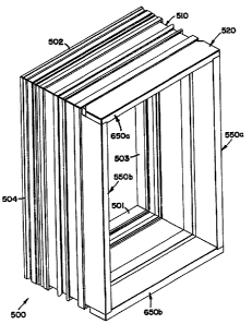
A preferred embodiment window and window frame
extension constructed according to the principles -of the
present-invention are collectively designated as 500 in
Figure 1.
Windova Frame
The window frame 510-includes four window frame
members 501-504 that are secured end to end at right
angles relative to one another to form the window frame
510. Each of the four window-frame-members 501-50_4 is
an extrusion of a composite material including wood and
t
polyvinyl chloride, and the cross-sectional profile
shown in Figure $. The window frame members 501-504~arew
welded to one another by applying heat until a bond
forms between some of the polyvinyl chloride-in each of
two adjacent members.-
CA 02203111 1997-04-18
WO 96f12861 PCTNS95113253
The specifics of~the window frame members 501-504
are shown and described in greater detail (with
reference-_to part number 600) in the more recently filed
parent application, U.S. Application Serial No.
5 08/490,400, which is incorporated heroin by reference to
same. Generally speaking, the frame members 501-504 are
suitable.for receiving a pocket replacement-window and
converting same for use in window-in/window out
replacement or new construction installation. The-
liners of the pocket replacement window simply snap into
place-on respective frame members 501-504.
A portibn of the window frame segment.504 is shown
in Figure 5 and-is representative-of corresponding
portions of the. other-window frame segments 501-503.
The segment 504 includes a main beam 517 which receives
and supports a respective liner of a window pocket. One
end of the beam 517 terminates in an interior end 510 of
the segment 504, which extends generally perpendicular
to the beam 517 from a wall engaging foot-511-at one end
thereof, to an aesthetically curved surface-'513 at an
opposite end. A channel is disposed between the foot -
511 and the surface 513 and opens towards the interior
of the window assembly 500. The cliannel515 is bounded
by a first, angled sidewall 516, a bottom wall 514 which
extends at an acute angle.rom the first sidewall 516,
and a second-sidewall 512 which extends-approximately
perpendicular to the bottom wall 514. -
Window Frame Extension
The window frame extension 520 includes two
vertical members 550a and 550b and two horizontal
members-650a and 650b which are connected to the window
frame 510, as well as oneanother. - The two vertical
members 550a and 550b are mirror images of one another,
and the two horizontal members 650a and 650b are.also
mirror images of one another. The window frame extension
520 is connected to the window 510 to provide additional
CA 02203111 1997-04-18
WO 96/12861 PCTNS95113255
6
depth and effectively span a rough opening of 2X6
construction. -
In the preferred embodiment, the members 550a and
550b are wood boards, but those skilled in the art-will
recognize-that the present-.invention-may be practiced
with members made of various materials.- Each of the
vertical members SSOa and S50b is an elongate board
having a continuous profile or-uniform cross-section -
which-is shown in Figure 3.. The profile may be said to-
be generally rectangular with a one-half dovetail-~ 60 at
one end thereof.- P. top surface 551 and a bottom surface
552 cooperate to define a-boaYd length therebetween. An
outwardly facing-surface 553 and an inwardly facing
surface 554 cooperate to define a board thickness
therebetween. A distal edge 555 and a parallel edge 564
of the one-half dovetail 560 cooperate-to define a board
depth therebetween. The top surface 551 and the bottom
surface 552 define obtuse angles relative to the distal
edge 555 for reasons discussed-below.
In addition to=the parallel edge 564, the one-half-
dovetail 560 includes an offset-edge or surface 561
which extends substantially parallel to the edge 564.
The offset edge 561 extends from a frameward end of the
outwardly facing surface 553 and cooperates-therewith to
define a generally square, external corner: A nested
surface 562 extends from an opposite- end of-the offset.
edge 561 and generally perpendicular thereto. A curved
surface-563 extends hetween and interconnects the nested
surface 562-and the parallel edge 564. The curved
surface 563 extends in generally arcuate fashion through
approximately ninety degrees and cooperates with the
nested surface 562 and the parallel-edge 564 to provide
a-continuous and smooth surface.
A fist-'beveled edge or surface 565 extends from an-
opposite end of the-parallel edge 564 at an obtuse angle
relative thereto. A second beveled edge or-surface 566
extends from an opposite end of the-first beveled edge
CA 02203111 1997-04-18-
WO 96112861 PCTlUS95/13255
7
565 at an acute angle~relative thereto-. An angled edge
567 extends between and interconnects the second beveled
' edge 566 and the inwardly facing surface 554. The
angled -edge 567 extends generally perpendicular to the
second beveled edge 566._ _ __
In the preferred-embodiment, the members 650a and
650b are also wood boards, but again, those skilled in
the art will recognize that the present invention may
be
practiced with members made of various materials. Each
-of the horizontal members 650a and 650b is an elongate
board having a profile or cross-section which is shown
in Figure 4. The profile is continuous or-uniform
except for--notches formed in each end of each of the
.
--- members 650a and 650b.- The overall profile is similar
-
to that of the vertical members 550a and 550b and thus,
may also be said to be generally rectangular with a one-
half dovetail 660 at one-end thereof. A top surface 651
and a bottom surface -552--cooperate to -define-a board
length therebetween. An outwardly facing surface 653
and-an inwardly facingsurface 654 cooperate to define
a
board thickness therebetween. -A distal edge 655 and a
parallel edge 664 0- the one-half-dovetail 660 cooperate
__ to define a=board depth therebetween.
In addition to--the parallel edge 664, the one-half
dovetail 660 includes an offset edge or surface 661 -
which extends substantially parallel to the edge 664.
The offset edge 661 extends from a-frameward end of the
outwardly facing surface-653 and cooperates therewith
to
define a generally square, external-corner. A nested
surface 662 eXtends-from an opposite end of theoffset
edge 661 and generally perpendicular thereto. A curved
surface 663 extends between and interconnects the nested
surface'66'2 and the parallel edge 664.-- The curved -.
surface-663 extends in generally arcuate,_fashion through
35- approximately ninety degrees and cooperates with the
nested surface 662 and the parallel edge 664 to provide
a continuous and smooth surface.-
CA 02203111 1997-04-18
WO 96/12861 PCT/US95113255
8
A first beveled edge ar surface-665 extends from an
opposite end of the parallel edge 664 at-an obtuse angle
relative thereto. A second beveled edge or surface 666
extends from an opposite end of the first beveled edge
665 at an acute angle relative thereto- An angled edge-
667 extends between and interconnects the second beveled
edge 666 and the--inwardly facing, surface 654. The-
angled edge,667 extends generally perpendicular to the
second beveled--edge 666'.
A first notch is formed in each end of each of the
members650a and 650b by cutting into the inwardly
facing surface 654. The cut defines a first plane or
edge 671 (or 6-75)- which generally intersects the
'-' juncture between the surfaces 654 and 667 and which
15- extends generally parallel-to a line extending from the
juncture or-corner=defined between the surfaces 666 and
667 to the juncture or corner defined between the-
surfaces '654 and 655. The cut also defines a second
plane or edge-672 (or 676) which extends between the
first plane 671 (or 675) and the inwardly facing surface
654 and generally perpendicular to each. Hence, the cut
into the inwardly facing surface 654 may be madesimply
__ by positioning either of the members 650a or 650b on a
table saw with the inwardly facing surface 654 facing
toward the table, and adjusting the--height of thesaw
blade to coincide with the juncture betweenthe surfaces
654 and 667. The width of the edge 671 (or675),-as
measured between the second edge 672 (or 676) and-the
end 651- (or 652), is approximately equal to the board
thickness of-the vertical member to_be secured adjacent
thereto. _.
A second notch is formed-in each end of -each of the
members ~Sba and 650b by cutting across the inwardly
facing surface 654 and the_one-half dovetail 660.== The
35- gut defines a plane or edge 673 (or67_7) which extends
substantially perpendicular relative to the inwardly
facing surface 654 and at angles of--approximately one -
- CA 02203111 1997-04-18
WO 96!12861 PCT/US95/I3255
9
hundred and thirty-five degrees relative to each of the
surfaces651-(or 652) and 664.--These second notches
provide clearance for the vertical members 550a and 550b
~ to be inserted into their respective-game members and
, rotated into their intended orientation relative
thereto.
Each of the extensian-members 550a-b and 650a-b is
connected to its respective Frame member in similar
fashion. pn eXplariation of this manner of
interconnection is made with reference to Figure-5,
which shows extension member 55-Ob-relative to its
respective frame member 504. The-extension member 550b
is positioned relative to the frame member 504 in such a
manner that the angled or: leading edge 5.67 is proximate
the channel 515 and generally at a mirrored angle
relative to the first sidewall 516 thereof. In other
words, in this starting position designated at 550b"~
the angled edge;567 and the first sidewall-516 define
approximately equal and opposite angles-relative to a
line drawn-across-the mount of the channel 515.
The dovetail segment 560 of the extension member
55Db is then moved into the channel 515 to arrive at an
intermediate position, which is designated at 560',
wherein the curved or trailing edge 562 approaches the
mouth of the channel 515 and the second sidewall 512.
The dovetail segment 560 of the extension member 550b is
then further inserted into and rotated within the
channel 515 to-arrive at a final position, which is
shown in solid lines, wherein the angled edge 567 is
parallel to the first sidewall 516,-and the parallel
edge 564 is parallel to the bottom sidewall 514, and the
nested edge 5-62 is parallel to-the second -sidewall 512.
In-this final position relative to the-frame segment
5D4, the extension member 550b cannot be pulled straight
out from the channel 515 (in a direction parallel to the
main beam 517 of the frame segment 504.
In the preferredembodiment, the horizontal members
CA 02203111 1997-04-18
WO 96112861 PCT/US95113255
650a-b are first connected to their- respective frame
segments 501 and 502.--The vertical members--550a-b are
subsequently connected to their respective frame
segments 503 and 504. The_resilience of the frame ~
5 segments 501 and 502 allows the horizontal (or top-and
bottom) extension members--650a=b to-rotate slightly away a
from one another tn.receive the vertical extension
members 550a-b therebetween. The notches across the
corners of the horizontal members 650a-b provide
10 clearance for-the dovetail-segments 560 of the vertical-
extension members 550a-b. As the vertical extension
members 550a-b are inserted between-the horizontal
members 650a-b and rotated into position relative to
their respective frame segments-503-504, the opposite
ends 551 and 552 thereof snap into-the. notches in the
inwardly facing surfaces 654 and behind the edges 672
and 676, respectively,-of the horizontal members 650a-b.
The resilience of the frame segments 501 and 502 then
causes--the horizontal (or top and bottom) extension
members 650a-b to rotate back toward nne another- to
retain the vertical extension members 55Oa-b
therebetween (without the-need for any additional-
fasteners). Two of-the-resulting corners are shown in
Figures 6-and 7.
An application of the present invention is shown in
Figure 8 with reference=to_a top view of a casement
window 700_ The casement window 700 includes a pocket
portion 720 which has been fitted with frame segments
501-504, which in turn; have been fitted with extension
=-members 550a-b and 650a-b. The-framed casement window
700 is secured within a rough opening bordered by 2 x 6
studs (2 of which are designated as.1913 and 1914) with
a wall-covered by inner and outer sheets 1915-1918. The
extension members 550a-b (and 650a-b) cooperate 4~ith the
frame segments 503-504 (and 501-502) to span the depth
of the opening. Trim pieces 593 and 594 finish off the
interior-of-the installed unit.
CA 02203111 1997-04-18
WO 96f12861 PCT/US95/13255
11
Alternative Embodiment
An alternative embodiment of the present invention
' is discussed with reference-to-Figures 9-11. In one
' application for this alternative-embodiment, a new
construction, double hung window assembly 800-includes
y extension jamb clips 841-844 secured about an inwardmost
portion of respective frame members (including 201 and
203), as well as outer=frame members-or-moulding
(including 881and-883)-secured about anoutwardmost
portion of respective.frame members (including 201 and
204), respectively. Extending from the outer frame
members 881-884 are nailing flanges (including 891 and
893), which are shown and described in-United States
Patent No. 4,958,469 to Plummer. To the-extent that it
15- facilitates understanding of the present invention, this
patent application is incorporated herein by reference
to same.
When thewindow assembly 800 is placed within the
rough opening 802, the frame.-members, extension jamb
clips, and outer frame members are adjacent respective
jambs (including 811 and 813). The nailing flanges are
arranged to extend outward from the outer-frame members
and to lie. substantially flush against the first
__, exterior sheet 815. Nails or other--fasteners are then
used-to secure the nailing flanges to the first exterior
-
sheet, either before or after a--second exterior sheet
816, such as wood siding, is placed-over-the nailing
flanges and the first exterior sheet. The nailing
flanges span and thereby seal any gap between the window
frame members and the jambs about-the xough opening. A
bead of caulk is then disposed along the juncture 817
between the outer frame members and the second exterior
sheet to provide an additional seal. The '.vindoci
assembly 800 is also secured within the rough opening by
scYews--through the side jamb liners and respective frame
members, and into-the side jambs 812 and 814,
respectively, and screws 821 through the head jamb liner
CA 02203111 1997-04-18
WO 96112861 PCTIUS95/13255
12
370 and the frame member 201, and into the. head jamb
811a. ' -
Recognizing that the three and one-half inch deep
window assembly 800 does not fully occupy the 2 x-6 '
5- rough opening, extension jambs 861-864--are provided to
span the unoccupied depth of the rough opening. Each of
the extension jambs 861-864 is-wood and has the cross-
sectional shape or profile of that shown in Figure=10
for thesill extension jamb 861.- The profile includes a
relatively long segment 865 and a-relatively short
segment-865 that are integrally joined at an obtuse
angle relative to one another-to define an elbow-867.
An opposite, distal end 868 of the longer=segment=865 is
square relative to the-sides of-the longer-segment 865,
as is an opposite, distal end 869 of the shorter-segment
866. The resulting configuration may be said to-provide
a half dovetail arrangement having,a leading corner 860
that is chamfered in the manner-shown.
Each of the-extension-jamb clips 841-844 has-the
cross-sectional shape or profile of..that shown in Figure
10 for-the clip 841. Theprofile includes a -
substantially S-shaped portion extending from an upper
distal end 848, laterally across an upper horizontal
_ member 847, downward along an upper-vertical member 846,
25V substantially laterally across an intermediate member
845,--downward along a-lower vertical member 853, and
laterally across a lower horizontal-member-850, to a
lower distal end 858. The-upper horizontal member 847,
the upper vertical member 846, and the-intermediate
member 845 define a channel or groove 849- therebetween,
having a substantially trapezoidal-profile=and opening
in a direction opposite the extension jamb 861. The
intermediate member 8_45, the lower vertical member 853,
and the lower horizontal--member 850-define a channel or
groove-859 therebetween,-having a substantially-
trapezoidal profile and opening-in-a direction toward
the extension jamb 861-. The lower horizontal member 850
CA 02203111 1997-04-18
WO 96!12861 PCTJUS95113255
13
and the lower vertical member 853 cooperate ta-define an
angle A therebetween. The angle~A is slightly less than-
ninety degrees, eight-e-fight degrees to be exact, so as
to provide a resilient clamping forceagainst an
extension jamb inserted therebetween. -The chamfered
~ corner 860 helps to wedge the end.869 between corner 857
and the end 858-of the wall 850.
The lowerhorizontal member 850 extends from the
distal end 858 beyond the-=lower vertical member 853 and
integrally joins an additional vertical member 851 that
may be said to be barbed. The barbed vertical member
851 cooperateswith the lower vertical member 853 and a
portion of the lower horizontal member 850 to define a
channel or groove-852, which opens in a direction away
from the lower horizontal member 850. A-shoulder 854
projects from the barbed vertical member 851 into the
groove 852..,The groove 852 receives the barbed end on
the window frame 201 and the respective shoulders on the
frame end-and the barbed vertical member 852 interengage
to resist withdrawal of the frame end from the groove -
852. In this manner, thejamb extension clips 841-844
are secured to the window frame members, respectively,
to arrive at the arrangement 840 shown in Figure 23.
The width of each channel 859 is substantially
similar to the width of the shorter-segment 866 ozi each
of the extension jambs 861-864. Beginning with each of
the side jamb extensions 862 and 864, each extension is
oriented relative to a respective clip as shown in
Figure 10._the angled side or leading-edge 876 is
30- positioned proximate the corner 857, and the shorter
segment 866 is i:iiserted into the channel 859 until the
leading corner 860 contacts the lower vertical member
853. Each of the_side extension jambs 862 and 864 is
-.-- then rotated relative to a respective clip 842 and 844 -.
35- in the manner indicated by the arrow R in Figure 10.
The corner 860_travels into a recessed area formed by
the acutely angled corner-856 between-the intermediate
CA 02203111 1997-04-18
WO 96112861 PCTIUS95113255
14
member 845-aiid the lower- vertical member 853; the end
869 moves into a substantially flush or aligned
orientation relative to the lower vertical member 853;
and a portion of the longer member 865 moves into a '
su-bstantially flush or aligned orientation relative to
the lower horizontal member 850. The same procedure is
then followed for the head jamb extension 861 and the
sill jamb extension 863. - --
As shown in Figure 9, the side jawb-clips 842 and
844 and-the side jamb extensions 862 and 864 extend
lengthwise substantially the entire length of the window
assembly 800: On-the other hand, the head jamb clip 841
and the sill jamb clip 843; and the head jamb extension
861 and the sill jamb extension 853 extend lengthwise
less than the entire width of the window assembly SDO,
because they are bordered at opposite ends by the side
jamb clips 8.42 and 844 and the side jamb extensions 862
and 864, respectively. The shortersegments 866 of the
head and sill jamb extensions 861 arid 863 extend
lengthwise the same distance-as the-head and sill:-jamb
clips 841 and-843, respectively.- The longer segments
865 of- the head and sill jamb extensians 861 and 863
extend lengthwise beyond the shorter segments 866 to
span the upper vertical members 846 of the.side jamb
clips 842 and 844 and abut the side jamb extensions 862-
and 864. Once the head and sill jamb extensions 861 and
863 are inserted into their respective clips 841 and 843
and rotated between the opposing side jamb extensions
862 and 864, the four jamb extensions are secured in
place by screws 898, which extend through holes 89.9 in
the side jamb extensions and into the head and sill jamb
extensions. This half dovetail extension jamb
arrangement 840 requires only four screws to assemble
and eliminates the need oruse of nails or-other
fasteners extending from the extension,jambs into the
window frame or associated structure.-
Once the extension jambs are secured in place, trim
CA 02203111 1997-04-18'-
WO 96112861 PCTI11S95/13255
members (including 871 and 873) are_secured between the
square ends 868 of-the respective extension jambs
(including 861 and 863) and the interior sheet of
material 817, either before or after the interior sheet
5 of material 817 is coated with paint or some other
finish.
A second application for the alternative embodiment
is discussed with reference to Figure 12, wherein
removal of an existing window assembly, including the
10 frame and moulding, leaves-a rough opening bounded by
structural members, in this case "2x4" boards
approximately three and one-half inches-wide and one and
one-half inches thick.
A suitably sized replacement window-901 is
15 positioned within the rough opening and secured in place
by means of screws 921 driven through the-head liner 370
and upper frame'member-201 and into-the head jamb 911a,
and screws driven through,the side jamb liners and side
frame members and into the respective side jambs.
Interior trim members ,(including 97_1 and 973) are
secured between the interior sheet of material 917 and
the. upper vertical members 846 on respective jamb clips
(including 841 and 843). Exterior trim members
(including 991 and 993) are secured to the exterior
sheet of material 916. A bead of--caulk -is disposed
along a corner defined between each of the trim members
and the exterior sheet of--material 916.'
The present invention is described with reference
to particular embodiments and applications. However,
those skilled in-the art will recognize-additional
embodiments and applications of the present invention.
Accordingly, the present invention is to be limited only
to- the extent of the following claims:
.. .. , ,: ..". ~,.