Note: Descriptions are shown in the official language in which they were submitted.
R~ YA ~IU~I~CHEN Ul ~ -96 : ~:-'8 ~ 3 0724~ +~9 8~ 23994465-# 4
-' -- ' --',--, .-- --- - -' CA 02203159 1997-04-18-- ~-- ---
APPARAT~S AND ~oeTHOD OF ~ ~'T-~T~
E:~ECl'aO~:C IW DTO SI~NAI,S
FI~Tn OF I~ .Nv~Nllo~
The present invention relates to apparatu~ and
~ethod for e~h~nc~ ng electronic audio 8i~nal8 in order to
improve the ~uality of 30und produced ~rom those 8ignal8,
and more particularly to an apparatus and method for
~Ar~l n~ enh~n~ing harmonics to the electronic audio
sig~al.
BACKG~OUND OF THE ~ N-llON
Hearing music, singins or other 6uch sounds live has
often ~een considered more pleasurable than hearing the
3ame ~ound a~ter it has been con~erted into an electronic
audio signal and re-conYerted bac~ into audible sound.
There can be many reasons for thi3 perceived drop in - -
quality. One reason reside~ in the ~ound reproduction
process itself.
Many of the ~ound~ we hear, e6pecially musical
n~tes, are often a compoeite. For example, a musical
note having a basic pitch or funA~m~ntal frequency,
u~ually contain~ component~ of the ~n~AmPntal frequency
called harmonics. ~he~e harmonic3 create the tonal
~uality or timbre of th~ sound, such a~ a mucical note,
that is o~ten unique to the musical in~tru~ent or other
~5 sound producing source. In other words, these harmonic~
enrich the sound we hear. While the human ear typi~ally
c~nnot discern the individual harmonic8, it can perceive
-~ tha pre~ence or ~hsen~ o~ the~e harmonics as a
respective increase or decrease in the quality of the
~ound. Devices for converti~g live ~ound into electronic
audio ~ignal~ ~for example, microphone~ or ~imilar
de~ice~) tyFically do n~t adequately regi~ter and convert
the full guality of the ~iv~ ~ound. Thu~, the electronic
audio signala do not include many of the original 't_
harmonic~. Numerous sound ~c~o~uction syatem8 ~uch as,
for example, equalizers and tone control~ have been
de~elopcd in an att~mpt to add harmonic e~han~ent to
such deficient audio signal~. However, the~e sy~tem9 are
o~ten ~ery ~ophi~ticated and expensi~e and the ~ound
Al\~''ENDED SHEET
CA 022031~9 1997-04-18
WO96/13gS9 PCT~S94/1~28
quality produced with such systems still falls short of
the original quality of the sound heard live.
Another reason reproduced sound is often perceived
to have a lower quality than live sound can be attributed
to the environment in which the sound is produced and
recorded. For example, music played in an open field
typically sounds one dimensional because much of the
sound waves dissipate into the field and are not heard by
a listener. On the other hand, music played in an
acoustically designed room usually sounds richer and
fuller, and individual sound sources, for example,
musical instruments, are typically more distinguishable.
One reason for this difference is that the sound heard by
the listener includes high quality reverberations which
combine to produce audible sound with a greater high
quality harmonic content.
Not all reproduced sound originates in an
acoustically designed environment and therefore does not
have the benefit of such high quality reverberations.
Even when an acoustically designed environment is used,
high quality reverberations may get lost in the recording
process, for instance, if the sound converting equipment
(for example, a microphone or the like) is unable to
register them.
2S Another problem with reproduced sound, such as
music, is that it can become distorted when heard at high
volumes. It is often difficult to clearly hear the words
being sung in a song or distinguish one musical
instrument from another as the volume increases.
An additional problem is that the quality of
recorded music being played in a room can vary depending
upon the room geometry and upon where the listener is
located in the room with respect to the sound source (for
example, speakers). When this occurs, the music sounds
better at one or more specific locations in the room.
Such locations are often referred to as sweet spots.
Thus, in order to enjoy the full potential of the
RC~ k~A ~!l.t~ U ~ 37 ~ ()7~4 +49 39 :~39~344~:i.5 . ~ 5
recorded music, a listener is forced ta remain at these
sweet spots.
~ ariou~ ~ophi~ticated and expen6i~e syste~s ha~e
been de~eloped in an effort to produce an en~n~d
electronic audio signal which, when con~er~ed into
audible ~ound, is percei~ed as more clo~ely duplicating
the experience of hearing the original li~e sound in an
acou~tically de~igned environmen~. The pre~ent in~e~tion
i~ an i~ UV~ t th~reon which is relati~ely inexpensive
and unco~plicated.
SUMMARY OF THE I~VENTION
~ n accordance with the present invention, methods
and apparatus are pro~ided ~or ~imply a~d 1nexpen~ively
enhancing an electronic audio sig~al in ~uch a way that
the quality of audible sound produced ~rom the audio
~ignal more closely approaches that of the original ~ound
a~ if heard live in an acou~ticall~ de~igned e~ir6nment.
The preaent in~ention imp~o~ the harmanic quality of an
elec~ronic audio aignal by amplifying e~h~ncing harmonic~
in the audio ~ignal. Sound pro~ from an a~dio signal
enh~ced in accorda~e with the present invent~on appear3
to resi~t becoming distorted at high volume~ and ten~s to
eliminate, or at least significantly reduce, the
~ormatio~ of ~weet spots.
To the~e ends, a~d in accordanc~ with the principle~
of the present in~rention, the clectronic audio signal is
tran3mitted through a magnetic coil audio energy tran6~er
system which rn~nce~ the electronic audio Qignal in such
a way that ~ e ~ound produced from the en~ce~ audio
signal is perceptibly richer and ~ull~r. More
~p~cificall~, the electronic audio 9ign~ electr~6ally
~ trans~itted through an electrom~n~tic field inducing
coil to generate a f~eld signal correlated to th~ -~
35 original ~lectro~ic audio sisnal. The field 3ignal is
~hen weakly or loo~ely coupl~d tc a field re~eptor which
con~ert~ the field signal into an enh~n~ed, but weak,
AMENDED SIIEET
RCV.~ k~A .~ 9~ 9 ; ~ 7'4~ +49 89 2~984465:# 6
~ ' CA 02203l59 l997-04-l8~
electronic audio ~ignal which may ~hen be amplified, if
neces~ry, for reproduction on conventional audio
r~producing equipment, such as speaker~ and the like.
With weak or 1Oo6e coupling, only a 5mall portion of the
electromagnetic field ~et up by the induci~g coil cuts o~
pa~6es through the ~ield receptor. The weak coupling af
the induced field signal to the receptor results in t~e
electronic audio ~ignal, and thus ~ound generated from
the signal, being enhanced by the accentuation of
lo desirable harmonics.
Weak or loose coupling between tho inducing coil a~d
the ~ield receptor cau~es the well known negati~e signal
distortion o~ the high fre~uencies being favored and low
~requencie~ being attenuated. The present invention 1~
predicated upon the di~co~ery that along with this type
of undesirable di~tortion or degradation there i~ al~o a
desirable d~stortion or enhA~l~ement~ It i3 believed that
thir- harmonlc enhance~ent r~mained undetected, unt~l now, .
becauf;e the negative distortion ( i . e ., favorin~ of high
frequencies at the exr~n~e of low frequencie9) made 3uch
har~onic enhance~ent unrecc~nizable. ~ecau~e the
unde~irable distoxtlon associated with weak coupling is
~a well e~tablished and well known and the discoYered
harmonic e~h~"~s~ent unknown, weak coupling ha~ been
avoided, not embraced, a~ in the present invention. The
inducing coil and the field r~ceptor are weakly or
1Oo8ely coupled in order to promote 'chis undesirable
- distortion because o~ the prc~iously ~n~nown har~onic
er~hAn~ement .
It i~ believed that the f~eld inducing c~il may b~ a
wiro w;n~;ng with at least on2 turn, but it is desirable
for the inducin~ coil to be a wire win~tn~ with a ~
~ plurality of turns. It is ~elieved that th~ rec~ptor may
be an electromagnetically c~n~ncti~e wire, plate, tube or
other structure, but it is desirable for the field
receptor to be a coil wlth a plurality of turn~. It is
deslra~le for the~ field inducing coil and the ~ield
, ~
A~E~!~rnS~EET
CA 022031~9 1997-04-18
WO96/13gS9 PCT~S94/12328
receptor coil to have the same number of turns, and even
more desirable for the field receptor coil to have more
turns than the field inducing coil. The inducing and
receptor coils may each be mounted on a separate core or
both mounted on a single shared core. It is desirable
for the cores to be non-permeable or low permeable cores,
for example, air, plastic and cardboard cores.
By virtue of the foregoing, there is thus provided a
simple and inexpensive apparatus and method for enhancing
an electronic audio signal so as to have a quality when
aurally reproduced approaching that of original live
sound as heard in an acoustically designed environment.
The objectives, features and advantages of the
present invention will become further apparent upon
consideration of the following description and the
appended drawings.
BRIEF DESCRIPTION OF THE DRAWINGS
Fig. 1 is a block schematic diagram of an audio
signal enhancing apparatus in accordance with the
principles of the present invention;
Fig. 2 is a perspective view of one embodiment of an
inducing coil and a field receptor coil according to the
present invention;
Fig. 3 is a circuit diagram of a dual channel audio
signal enhancing apparatus similar to the apparatus of
Fig. 1; and
Fig. 4 is a diagrammatic sectional side view of an
alternative embodiment of an inducing coil and a field
receptor coil according to the present invention.
DETAILED DESCRIPTION OF THE INVENTION
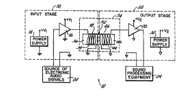
Referring to Fig. 1, there is shown one embodiment
of a system 10 for enhancing electronic audio signals
- according to the principles of the present invention.
System 10 includes an input stage 12 having power supply
14, input amplifier 16, and electromagnetic field
inducing coil 18 through which multiple frequency input
electronic audio signals are driven by amplifier 16 to
CA 022031~9 1997-04-18
WO96/13gS9 PCT~S94/123~
generate a field signal correlated to the original input
signal from a source 20 of electronic audio signals, such
as a microphone, magnetic tape player, optical disc
player, radio receiver, television audio receiver,
telephone receiver or the like. System 10 also includes
an output stage 22 for converting the generated field
signals from input stage 12 into electronic audio signals
which are enhanced according to the principles of the
present invention and which may be reproduced into
lo audible sound by conventional sound producing equipment
24, such as speakers and the like, or recorded onto a
recording medium. Output stage 22 includes a field
receptor 26 connected to output amplifier 28 which is
powered by power supply 30. Field receptor 26 is
positioned to receive very weak portions of the field
signal created by coil 18 without inducing any
appreciable amounts of undesirable feedback currents in
coil 18.
Input amplifier 16 is a power amplifier which
20 greatly amplifies and drives the input signal from source
20 through coil 18 of input stage 12 with sufficient
strength to be received by receptor 26 for conversion
into an enhanced electronic audio signal comprising the
original input signal plus additional desirable
25 harmonics. The field signal thus induced at coil 18 is
weakly coupled to field receptor 26 of output stage 22.
That is, the receptor 26 is placed within the field
created by coil 18 but at a sufficient distance
electromagnetically so as to receive the enhanced signals
without introducing undesirable feedback in coil 18.
Weakly coupled coil 18 and receptor 26 form a magnetic
coil audio energy transfer system 54.
It is believed that coil 18 may be a single-turn
coil of insulated wire 34 wound on a core 36 and that
35 receptor 26 may be a conductive wire, tube or plate.
However, it is desirable for both coil 18 and receptor 26
to be a multiple-turn coil of insulated magnetic wire 34
CA 022031~9 1997-04-18
WO96/13g59 PCTtUS94tl2328
and wire 44, respectively, with the same number of turns.
While coils 18 and 26 are shown as being cylindrical or
circular in shape, the present invention is not intended
to be so limited. Receptor coil 26 is wound on a core 46
which desirably forms part of the same core as core 36.
In response to the field signal from coil 18, the
enhanced electronic audio signal is generated in the
receptor coil 26 but, because of the weak coupling, at a
very low amplitude compared to the input signal driven
through coil 18. The enhanced signal is so weak as it
passes through receptor coil 26 that any field signal
that the enhanced signal may induce is too weak to
generate a significant feedback signal of its own in coil
18. The output of coil 26 is connected to output
15 amplifier 28 in order to amplify the enhanced signal
enough to be used by the sound reproduction equipment 24.
It will be appreciated that the field signal induced
by coil 18 is weaker for lower frequencies than for
higher frequencies. Therefore, the lower frequencies of
20 the enhanced audio signal generated by receptor coil 26
are weaker than its higher frequency components. In
other words, before it is amplified, the high frequency
end of the enhanced audio signal has a higher amplitude
(power level) than its low frequency end as compared to
25 the original input audio signal driven through coil 18.
It is therefore desirable for the output amplifier 28 to
include a frequency shaping network 109 (see Fig. 3)
which favors the low frequencies and attenuates the high
frequencies so that the net result is a fairly flat
30 frequency response when comparing the input audio signal
before it enters input stage 12 and the enhanced audio
signal as it leaves output stage 22.
As seen in Fig. 2, it is desirable for cores 36 and
46 to each form part of a single core member 52 such that
35 coils 18 and 26 are coaxial along central axis 48 and
spaced apart by a distance G. Although shown as a tube
of cardboard, plastic or other suitable material with a
CA 022031~9 1997-04-18
WO96/139S9 PCT~S94/12328
circular cross-section, core 52 could have other
cross-sections, such as rectangular, and could be a solid
bar of acrylic or other sufficiently low permeability
material. By being wound on a single core 52, it can be
seen that coils 18 and 26 of energy transfer system 54
appear as the primary and secondary, respectively, of a
lossy transformer. That is, the coupling between the
coils 18 and 26 is deliberately weak so that there is
little, if any, actual transformer action between the
coils. Rather, coil 26 is believed to act primarily as a
receptor of the field induced by coil 18 and is thus
positioned relative to coil 18 so as not to significantly
distort the enhancement of the input signal. The use of
low permeability cores is desired and contributes to the
weak coupling between the coils as is advantageous in the
present invention. Also, by using one or more low
permeability cores, such as with a permeability of
approximately 1 or unity, the coils 18 and 26 can be kept
close enough together to enable the input and output
stages 12 and 22 to be housed in a relatively small
package. Use of higher permeability cores, and perhaps
even a ferromagnetic core, may suffice although the
spacing between the coils will likely become large to
maintain the weak coupling. Additionally, other than a
coil, it is believed that receptor 26 could instead be a
magnetically conductive plate, length of wire, tube or
other structure which will receive and convert the field
induced by coil 18 to a new and enhanced electronic audio
signal.
To enhance the operation of system 10, it is desired
that the input stage 12 and output stage 22 be well
isolated, electrically and electromagnetically (except
for the weak field coupling through system 54, at the
interface of coils 18 and 26). To this end, separate
power supplies 14 and 30 are provided in the respective
stages 12 and 22, each with a separate ground. Also,
each of the power supplies 14, 30 is kept physically
CA 022031~9 1997-04-18
WO96/13959 PCT~S94/1~28
remote from both stages 12, 22 or shielded from stages
12, 22 such as with shielding techniques and materials
well known in the art.
A conventional audio signal source 20 (such as a
microphone, magnetic tape player, optical disc player,
radio receiver, television audio receiver, telephone
receiver or the like) is usually connected to a sound
producing device 24, such as a speaker. When the device
24 converts the electronic audio signal from conventional
source 20 into audible sound, the sound produced does not
have the degree of richness and fullness (the quality)
that the original live sound possessed before being
recorded. The quality of the audio sound produced is
substantially enhanced by the introduction of the present
inventive system 10 between the source 20 and the device
24. The electronic audio signal output from signal
source 20 is connected to the input stage 12 and the
output of output stage 22 is connected to the input of
sound converting device 24 so that any electronic audio
signal must pass through the magnetic coil audio energy
transfer system 54 before being converted into audible
sound. When this audible sound is heard by a listener,
its quality is enhanced to the point of sounding as if
the original performance were being played live and in an
acoustically superior environment. Preferably, two
systems 10 (i.e., dual channels) are used, one for each
respective channel of a stereo sound reproduction system.
One dual channel version of system 10 was built with
the following commercially available electronic
components:
(a) Dual Channel Input Amplifier (16) - Realistic
S-20 solid state stereo 12 watt amplifier, Model No. 31-
B;
(b) Two Input Coils (18) - Each a standard speaker
coil, rated at 8 ohms and 2 watts;
(c) Two Receptor Coils (26) - Each a standard
speaker coil, rated at 8 ohms and 2 watts; and
CA 022031~9 1997-04-18
WO96113959 PCT~S94/12328
(d) Dual Channel Output Amplifier (28) - Realistic
stereo 1.5 watt pre-amplifier, Model No. 42-2109.
The above speaker coils 18, 26 were taken from 3
inch diameter speakers manufactured by the Tandy
Corporation, Model No. 40-248. Each winding 18, 26 had a
width W (see Fig. 2) of about .15 inches (.38 cm), an
inside diameter of approximately .52 inches (1.32 cm),
and was formed by two layers of about 30 turns (about 60
turns total) of magnet wire having a length of
approximately 105 inches (267 cm) and a diameter of about
.005 inches (.013 cm), including its insulation. Each
pair of windings 18, 26 were mounted coaxially on a
single core 50 of solid acrylic having a rectangular
cross section of approximately 3/4 by 1/4 of an inch (1.9
x .64 cm) and passing completely through both coils 18,
26. The gap G between the coils 18, 26 was on the order
of approximately .060 inches (.152 cm). The Realistic
amplifiers were also manufactured by the Tandy
Corporation. Generally, the degree of amplification of
the audio signal provided by the input amplifier 16 and
the optimum gap G between the windings 18, 26 (see Fig.
2) are directly related. For example, with all other
variables remaining the same, as the amplification of the
audio signal by the input amplifier 16 increases, it is
believed that the gap G will eventually need to be
increased. As previously noted, the gap G is believed to
also vary directly with the permeability of the core 52.
This early embodiment of the present invention produced
enhanced sound but also exhibited some undesirable
characteristics. To overcome these problems, another
dual channel embodiment of system 10 was built as now
will be described with reference to Fig. 3.
Turning now to Fig. 3, there is shown a detailed
schematic illustration of a dual channel or stereo
version 100 of system 10 including a left side system lOa
and an identical right side system lOb. Systems lOa and
lOb share common input stage power supply 14 and common
CA 022031~9 1997-04-18
WO96/13959 ~ 5S/1~28
output stage power supply 30 as will be described. The
input and output stages 12a, 12b and 22a, 22b of the two
systems lOa, lOb are identical and therefore only the
circuitry of system lOa will be described in any detail,
it being understood that system lOb is the same.
More specifically, input stage 12a includes a first
pair of electronic audio inputs 70, 72 connected
respectively to the ground (GNDl) of power supply 14 and
of input stage 12a, and to 10 Kohm potentiometer 74. The
wiper of potentiometer 74 is connected via 10 ~F
capacitor 76 to the non-inverting input of an LM383
operational amplifier 78. The output 80 of amplifier 78
is fed back to its inverting input from the junction of
1/2 watt grounded series resistors 84, 85 (200 ohm and 10
ohm, respectively), through 470~F capacitor 86. Output
80 of amplifier 78 is further connected to GNDl via the
series branch of 1 ohm, 1/2 watt resistor 88 and .2 ~F
capacitor 90. Output 80 is next connected to the
inducing coil 18 of magnetic coil audio energy transfer
system 54 through 2,200 ~F capacitor 92 to drive the
electronic audio signal from inputs 70, 72 through coil
18 and induce the field signal as previously described.
Energy transfer system 54 includes field receptor 26
which is connected to a 1 Kohm potentiometer 96, the
wiper of which is connected through 10 Kohm resistor 98
and 1 ~F capacitor 101 to the non-inverting input of a
LM1458N operational amplifier 102. The coil 18 and
receptor 26 are each the same standard 8 ohm, 2 watt
speaker coil found in the previously described version of
system 10 using commercially available electronic
components. Energy transfer system 54, both coil 18 and
receptor 26, were fully encapsulated with a low
permeability polymeric potting material for structural
integrity. DP-270, a black epoxy potting
compound/adhesive manufactured by 3M, St. Paul,
Minnesota, provided sufficient structural strength and
low permeability. Both coils 18 and 26 are potted in
CA 022031~9 1997-04-18
WO96/13959 PCT~S94/1~28
their original cylindrical configuration and in the
coaxial orientation shown in Fig. 2, with a gap G of
approximately .025 inches (.0635 cm). Output 104 of
amplifier 102 is connected to enhanced audio output port
106 which, in cooperation with grounded output port 108,
provides the enhanced electronic audio signal to
reproducing equipment 24 as previously described. The
junction of resistor 98 and capacitor 101 is connected to
the output stage power supply ground (GND2) through a
shaping circuit 109 comprised of three parallel circuit
branches as follows: the series circuit of S.1 Kohm
resistor 110, .05 ~F capacitor 111, and open ended 50
Kohm potentiometer 112; .002 ~F capacitor 114; and the
series circuit of 5.1 Kohm resistor 116 and .1 ~F
capacitor 117.
The output 104 of amplifier 102 is connected back to
its inverting input via the series circuit of: parallel
499 Kohm resistor 122 and .005 ~F capacitor 123; parallel
49.9 Kohm resistor 124 and .01 ~F capacitor 125; parallel
10.0 Kohm resistor 126 and .005 ~F capacitor 127; and
lo.o Kohm resistor 128. The inverting input of output
amplifier 102 (as well as the inverting input of the
comparable output amplifier in system lOb) is connected
to a regulated voltage from regulator 129 of power supply
30 via 1.5 Kohm resistor 130 to the junctio~ o 510 ohm
resistor 132 and 5 volt zener diode 134 and 10 ~F
capacitor 136 which, at node 137, is at 5 volts. The
non-inverting input of output amplifier 102 is similarly
coupled to the 5 volt reference 137 via 100 Kohm resistor
138.
With respect to the power supplies 14 and 30, a dual
transformer 140 provides about 14 volts to the balance of
each supply 14 and 30, as will now be described. Input
stage power supply 14 includes a diode bridge 142 which
produces a full-wave rectified output from one 14 volt
output of dual transformer 140. The full-wave rectified
output is smoothed (filtered) by the circuit comprised of
CA 022031~9 1997-04-18
WOg6113gS9 PCT~S94/12328
1 ohm, 1/2 watt resistor 144, 2200 ~F capacitor 145, 10
Kohm, 1/2 watt resistor 146 and 1 ~F capacitor 147 to
provide a nominal 18 volt unregulated supply and ground
(GND1) for each of the input stages 12a and 12b.
Similarly, the output stage power supply 30 includes a
full-wave rectifier diode bridge 150 connected to the
other 14 volt output of dual transformer 140. The output
of bridge 150 is smoothed by the circuit comprised of 100
ohm, 1/2 watt resistor 151, 470 ~F capacitor 152, 10
Kohm, 1/2 watt resistor 153 and 1 ~F capacitor 154 to
provide a nominal unregulated 18 volts to voltage
regulator 129. The output of the voltage regulator 129
is bypassed to ground (GND2) via 10 ~F smoothing
capacitor 158 and .01 ~F smoothing capacitor 160 and
provides a regulated 12 volt supply and ground (GND2) for
each of the output stages 22a and 22b. Capacitor 158
provides filtering for lower frequencies and capacitor
160 provides filtering for higher frequencies. Note that
the input amplifiers 78 of each system lOa and lOb have
been provided in separate integrated circuit packages and
independently powered from supply 14 whereas output
amplifiers 102 of each output stage 22a and 22b have been
provided in a single integrated circuit package and
powered in common from power supply 30.
To prevent interference with the respective audio
signals, it is desirable for that portion of power
supplies 14, 30 before respective capacitors 147 and 154
to be kept remote from the input and output stages or, as
previously discussed, shielded. In addition, the energy
transfer system 54 (field inducing coil and field
receptor) for each channel may also need to be shielded
to protect system 54 from any unwanted interference
- external or otherwise.
In operation, the electronic audio signal for each
channel is connected, by a standard jack or the like (not
shown), to the respective input ports 70, 72. As will be
appreciated, the electronic audio signal will normally
CA 022031~9 1997-04-18
WOg6/13g5g PCT~S94/12328
include a wide range of audio frequencies. The
respective input levels are adjusted at potentiometers 74
so that the input signal levels of the two channels are
about equal and to allow input amplifiers 78 to amplify
the input signals to the maximum extent possible without
clipping or otherwise adversely distorting the input
signals. The audio signals are then enhanced through
energy transfer system 54 and the enhanced signals
adjusted in level by respective potentiometers 96 and for
the desired flat frequency response by respective
potentiometers 112 which may also be used to alter the
shaping networks 109 somewhat to adjust the tonal quality
as desired for the listener. The enhanced audio signals
are then amplified by amplifier 102 and connected through
outputs 106 and 108 (such as by a standard jack) to sound
reproduction equipment 24, such as another amplifier or
speaker system, and is converted into audible sound.
Alternatively, equipment 24 may be another recorder of
electronic audio signals for recording the enhanced audio
signals onto some form of recording medium, for example,
magnetic tape or optical disk.
Referring to Fig. 4, it has been found more
desirable for the magnetic coil audio energy transfer
system 54 to be formed with a receptor coil 27 having a
greater number of turns than its inducing coil 19. The
receptor coil 27 is wrapped around a cylindrical core 53
made according to the principles of the present
invention. For example, core 53 could be solid, made
with a low permeability plastic material, and have a
shoulder flange 55 at one end. Core 53 could also be an
air core formed with or without a tube (similar to core
52) of cardboard, plastic or other suitable material.
The inducing coil 19 is wrapped around the outside of the
receptor coil 27. Each coil 19 and 27 has respective
leads 21a, 21b and 29a, 29b, with each lead passing
through a hole formed through flange 55. Each of the
leads 21a, 21b and 29a, 29b are adapted for being
14
K~ A .~l~t`.~ -96 ; ~ 37 )~ ~7'~ +49 ~9 ~3994~5 # 7
~ --' CA 02203159 1997-04-18--~
connected into an appropriate circuit. By increasing the
numbex of turn~ in the receptor coil Z7 compared to the
inducing coil 19, an electrcnic audio signal driven
through the inducing coil 19 does not have to be
amplified a~ muc~ ln order to inducs a ~ignal of
su~ficient stren~th in the re~eptor coil ~7.
Whil~ the pre~ent invention has been deacri~ed and
illu~trated with reference to a number of embodi~ents,
and wh~le the~e en~bo~ mC'ntB ha~re been described in
considerable detail, there is no int~nticn to restrict or
in ~ny wa~ it the ~cope of the appended claim6 to such
detail. Additional ad~antages and modifications will
readily apFear to ~hose skilled in the art. For i~tance,
if the mu~ic or vocals from a compact disc player, in the
form o~ electronic audio signals, i9 tran~mitted through
Yy~tem 100 of the present in~ention and the re~ulting
e~h~nced electronic audio ~gnal re-recorded onto a
cassette tape u~ins a ca~eette player¦recorder, the
quality of the mu~ic or vocal~ produced from the recorded
~0 ca~sette tape has been found to be percep~ibly better
than the ~ame music or ~ocals produced direct~y from the
compact disc. Thi~ occur~ even though the compact disc
form~t ia widely recognized as produci~g superior sound
quality ~o~p~ed to the ca~ette tape format. It is
believed that the present in~ention can be u~ed to
~h~n~e electronic audio signals fram sound co~erting
e~p~ent, for example a microFh~ne or the like, before
belng elthcr recorded onto a recording medium (for
eY~mple,-,ma~netic tape or optical disk), transmitted
30 thrcugh the air ~or exa~ple, for television or cellular
tel~pho~) or co~v~Led directly into ~vd;~le sound (for
eY~mrle, at a concert or play). _~
The in~rention in its broader aspect~ i8 therefore
not limited to ch~ spe~ific deta~ 13, rzpresentati~e
3S apparatu~ and method, and illu~txative examples ~hown and
deacribed. Accordingly, departures ~ay be made fro~ such
.AMEND'~S~
K~ I'A ~ 7 ~ 4 +~ 89 '~;39'~44~;.5 . ~ 8
details without departing ~rom the spirit or ~ope of the
general in~res~ti~rc concept o~ the present in~rention.
What i~ claimed i~;
AM~NDED S'~t~