Some of the information on this Web page has been provided by external sources. The Government of Canada is not responsible for the accuracy, reliability or currency of the information supplied by external sources. Users wishing to rely upon this information should consult directly with the source of the information. Content provided by external sources is not subject to official languages, privacy and accessibility requirements.
Any discrepancies in the text and image of the Claims and Abstract are due to differing posting times. Text of the Claims and Abstract are posted:
| (12) Patent Application: | (11) CA 2203213 |
|---|---|
| (54) English Title: | HEAT SINK WITH COOLANT ACCELERATOR |
| (54) French Title: | PUITS DE CHALEUR AVEC ACCELERATEUR DE DEBIT DE LIQUIDE DE REFROIDISSEMENT |
| Status: | Deemed Abandoned and Beyond the Period of Reinstatement - Pending Response to Notice of Disregarded Communication |
| (51) International Patent Classification (IPC): |
|
|---|---|
| (72) Inventors : |
|
| (73) Owners : |
|
| (71) Applicants : |
|
| (74) Agent: | MARKS & CLERK |
| (74) Associate agent: | |
| (45) Issued: | |
| (22) Filed Date: | 1997-04-21 |
| (41) Open to Public Inspection: | 1997-11-30 |
| Availability of licence: | N/A |
| Dedicated to the Public: | N/A |
| (25) Language of filing: | English |
| Patent Cooperation Treaty (PCT): | No |
|---|
| (30) Application Priority Data: | ||||||
|---|---|---|---|---|---|---|
|
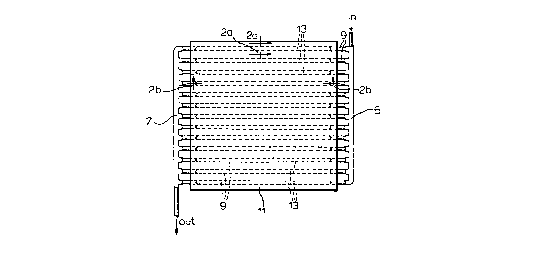
A liquid cooled heat sink for removing unwanted heat from a heat source,
comprising a thermal conductive surface connected to the heat source; a front end
head of predetermined diameter for receiving a supply of cooling liquid at a
predetermined volumetric flow rate; a rear end head of the predetermined diameter
for outputting the cooling liquid at the volumetric flow rate; a plurality of pipes of
the predetermined diameter connected outwardly to the heat source for conveying
the cooling liquid between the front end head and the rear end head thereby
withdrawing the unwanted heat from the heat source via the thermal conductive
surface; and an insert in at least one of the plurality of pipes for accelerating flow
of the cooling liquid in the at least one of the plurality of pipes thereby enhancing
thermal performance of the heat sink.
La présente invention vise un puits de chaleur servant à absorber la chaleur non utilisée d'une source chaude, et comportant une surface thermoconductrice reliée à la source en question, une tête avant de diamètre prédéterminé, servant à recevoir une certaine quantité de liquide de refroidissement à un débit volumétrique préétabli; une tête arrière de diamètre prédéterminé servant à refouler le liquide de refroidissement à un débit volumétrique préétabli; un réseau de canalisations reliées par l'extérieur à la source de chaleur et servant à transporter le liquide de refroidissement entre la tête avant et la tête arrière, où la chaleur non utilisée est absorbée par la surface thermoconductrice, et une pièce rapportée insérée dans au moins une des canalisations du réseau et servant à accélérer le débit du liquide de refroidissement de manière à augmenter la performance du puits de chaleur.
Note: Claims are shown in the official language in which they were submitted.
Note: Descriptions are shown in the official language in which they were submitted.
2024-08-01:As part of the Next Generation Patents (NGP) transition, the Canadian Patents Database (CPD) now contains a more detailed Event History, which replicates the Event Log of our new back-office solution.
Please note that "Inactive:" events refers to events no longer in use in our new back-office solution.
For a clearer understanding of the status of the application/patent presented on this page, the site Disclaimer , as well as the definitions for Patent , Event History , Maintenance Fee and Payment History should be consulted.
| Description | Date |
|---|---|
| Inactive: IPC from MCD | 2006-03-12 |
| Inactive: Office letter | 2004-03-23 |
| Inactive: Inventor deleted | 2000-07-05 |
| Inactive: Inventor deleted | 2000-07-05 |
| Inactive: Inventor deleted | 2000-07-05 |
| Inactive: Inventor deleted | 2000-07-05 |
| Inactive: Inventor deleted | 2000-07-05 |
| Time Limit for Reversal Expired | 2000-04-25 |
| Application Not Reinstated by Deadline | 2000-04-25 |
| Deemed Abandoned - Failure to Respond to Maintenance Fee Notice | 1999-04-21 |
| Application Published (Open to Public Inspection) | 1997-11-30 |
| Inactive: IPC assigned | 1997-07-30 |
| Inactive: IPC assigned | 1997-07-30 |
| Inactive: First IPC assigned | 1997-07-30 |
| Inactive: Filing certificate - No RFE (English) | 1997-07-17 |
| Filing Requirements Determined Compliant | 1997-07-17 |
| Letter Sent | 1997-07-17 |
| Abandonment Date | Reason | Reinstatement Date |
|---|---|---|
| 1999-04-21 |
| Fee Type | Anniversary Year | Due Date | Paid Date |
|---|---|---|---|
| Application fee - standard | 1997-04-21 | ||
| Registration of a document | 1997-04-21 |
Note: Records showing the ownership history in alphabetical order.
| Current Owners on Record |
|---|
| R-THETA INC. |
| Past Owners on Record |
|---|
| DAVID W. FAST |
| DEO RAMPERSAUD |
| JAMES R.S. BUTLER |
| MARIO J. CHILANSKI |
| MICHAEL RADOSEVIC |

