Sélection de la langue

Search

Sommaire du brevet 2203213 

Énoncé de désistement de responsabilité concernant l'information provenant de tiers

Une partie des informations de ce site Web a été fournie par des sources externes. Le gouvernement du Canada n'assume aucune responsabilité concernant la précision, l'actualité ou la fiabilité des informations fournies par les sources externes. Les utilisateurs qui désirent employer cette information devraient consulter directement la source des informations. Le contenu fourni par les sources externes n'est pas assujetti aux exigences sur les langues officielles, la protection des renseignements personnels et l'accessibilité.

Disponibilité de l'Abrégé et des Revendications

L'apparition de différences dans le texte et l'image des Revendications et de l'Abrégé dépend du moment auquel le document est publié. Les textes des Revendications et de l'Abrégé sont affichés :

  • lorsque la demande peut être examinée par le public;
  • lorsque le brevet est émis (délivrance).
(12) Demande de brevet: (11) CA 2203213
(54) Titre français: PUITS DE CHALEUR AVEC ACCELERATEUR DE DEBIT DE LIQUIDE DE REFROIDISSEMENT
(54) Titre anglais: HEAT SINK WITH COOLANT ACCELERATOR
Statut: Réputée abandonnée et au-delà du délai pour le rétablissement - en attente de la réponse à l’avis de communication rejetée
Données bibliographiques
(51) Classification internationale des brevets (CIB):
  • F28D 1/053 (2006.01)
  • F28F 13/08 (2006.01)
  • H01L 23/473 (2006.01)
(72) Inventeurs :
  • BUTLER, JAMES R.S. (Canada)
  • CHILANSKI, MARIO J. (Canada)
  • FAST, DAVID W. (Canada)
  • RADOSEVIC, MICHAEL (Canada)
  • RAMPERSAUD, DEO (Canada)
(73) Titulaires :
  • R-THETA INC.
(71) Demandeurs :
  • R-THETA INC. (Canada)
(74) Agent: MARKS & CLERK
(74) Co-agent:
(45) Délivré:
(22) Date de dépôt: 1997-04-21
(41) Mise à la disponibilité du public: 1997-11-30
Licence disponible: S.O.
Cédé au domaine public: S.O.
(25) Langue des documents déposés: Anglais

Traité de coopération en matière de brevets (PCT): Non

(30) Données de priorité de la demande:
Numéro de la demande Pays / territoire Date
08/656,513 (Etats-Unis d'Amérique) 1996-05-31

Abrégés

Abrégé français

La présente invention vise un puits de chaleur servant à absorber la chaleur non utilisée d'une source chaude, et comportant une surface thermoconductrice reliée à la source en question, une tête avant de diamètre prédéterminé, servant à recevoir une certaine quantité de liquide de refroidissement à un débit volumétrique préétabli; une tête arrière de diamètre prédéterminé servant à refouler le liquide de refroidissement à un débit volumétrique préétabli; un réseau de canalisations reliées par l'extérieur à la source de chaleur et servant à transporter le liquide de refroidissement entre la tête avant et la tête arrière, où la chaleur non utilisée est absorbée par la surface thermoconductrice, et une pièce rapportée insérée dans au moins une des canalisations du réseau et servant à accélérer le débit du liquide de refroidissement de manière à augmenter la performance du puits de chaleur.


Abrégé anglais


A liquid cooled heat sink for removing unwanted heat from a heat source,
comprising a thermal conductive surface connected to the heat source; a front end
head of predetermined diameter for receiving a supply of cooling liquid at a
predetermined volumetric flow rate; a rear end head of the predetermined diameter
for outputting the cooling liquid at the volumetric flow rate; a plurality of pipes of
the predetermined diameter connected outwardly to the heat source for conveying
the cooling liquid between the front end head and the rear end head thereby
withdrawing the unwanted heat from the heat source via the thermal conductive
surface; and an insert in at least one of the plurality of pipes for accelerating flow
of the cooling liquid in the at least one of the plurality of pipes thereby enhancing
thermal performance of the heat sink.

Revendications

Note : Les revendications sont présentées dans la langue officielle dans laquelle elles ont été soumises.


We Claim
1. A liquid cooled heat sink for removing unwanted heat from a heat
source, comprising:
a) a thermal conductive surface connected to said heat source;
b) a front end head of predetermined diameter for receiving a supply of
cooling liquid at a predetermined volumetric flow rate;
c) a rear end head of said predetermined diameter for outputting said
cooling liquid at said volumetric flow rate;
d) a plurality of pipes of said predetermined diameter connected
outwardly to said heat source for conveying said cooling liquid between said front
end head and said rear end head thereby withdrawing said unwanted heat from saidheat source via said thermal conductive surface; and
e) an insert in at least one of said plurality of pipes for accelerating
flow of said cooling liquid in said at least one of said plurality of pipes thereby
enhancing thermal performance of said heat sink.
2. The liquid cooled heat sink of claim 1, wherein said insert further
comprises a cylindrical portion of further diameter less than said predetermineddiameter, thereby creating an annulus there between, and at least two ribs for securing
said insert inside said at least one of said plurality of pipes.
3. The liquid cooled heat sink of claim 2 wherein said insert is
characterized by a cross sectional area which is approximately one half that of said at
least one of said plurality of pipes.
4. The liquid cooled heat sink of claim 2, wherein said insert further

comprises a pair of conical extensions from opposite ends of said cylindrical portion.
5. The liquid cooled heat sink of claim 2, wherein said insert is secured
within said at least one of said plurality of pipes via an interference fit.
6. The liquid cooled heat sink of claim 5, wherein said at least one of said
plurality of pipes further includes at least two grooves for receiving said at least two
ribs.
7. The liquid cooled heat sink of claim 2, wherein said insert is
characterized by a length which is approximately the same as that of said at least one
of said plurality of pipes.
8. The liquid cooled heat sink of claim 1, wherein said thermal
conductive surface comprises an aluminum block.
9. The liquid cooled heat sink of claim 8, wherein said plurality of pipes
are copper tubes inserted in said aluminum block.

Description

Note : Les descriptions sont présentées dans la langue officielle dans laquelle elles ont été soumises.

CA 02203213 1997-04-21
HEAT SINK WITH COOLANT ACCELERATOR
Field of the Invention
The present invention relates in general to heat sinks, and more particularly toa liquid cooled heat sink with coolant accelerator.
Background and Summary of the Invention
0 Liquid cooled heat sinks are known in the prior art for removing heat from
electronic components. One such liquid cooled heat sink is illustrated in Figure 1(a).
This heat sink typically comprises an al~-min~l~n block l incorporating a tube channel
3 which winds its way several times through the heat sink. The temperature of the
cooling liquid increases as it passes through the serpentine channel 3, picking up heat
from the electronic components being cooled. This results in uneven cooling and
lower life expectancy of the components towards the end of the sel ~enlil-e channel 3 .
Therefore, according to one aspect of the present invention, as discussed in
greater detail below with reference to the drawings, parallel paths of flow are
provided rather than a single winding tube channel in order to provide a balanced
2 o te.--pe- al~lre gradient over the whole heat collecting surface.
In order to achieve similar thermal performance as the prior art serpentine
arrangement of Figure 1(a), the parallel flow arrangement according to the present
invention must provide the same average fluid velocity in each of the parallel paths.
Since volumetric flow rate is determined by the pump system (i.e. a cor.s~a,ll flow
2 5 rate), each parallel path receives only a fraction of the liquid flow which is supplied to
the heat sink. Therefore, the cross-sectional area of each of the parallel paths must be
~djusted to compensate for the lower flow rate. According to the prere..ed
embodiment, an insert or accelerator is provided in each of the parallel flow paths for
accelerating the flow of cooling liquid, thereby enhancing thermal pel rOl ~llance of the
3 o heat sink.

CA 02203213 1997-04-21
Brief Description of the Drawings
A detailed description of the prefel I ed embodiment is provided herein below
with reference to the following drawings in which:
Figure l (a) shows a series-connected liquid cooled heat sink according to the
prior art;
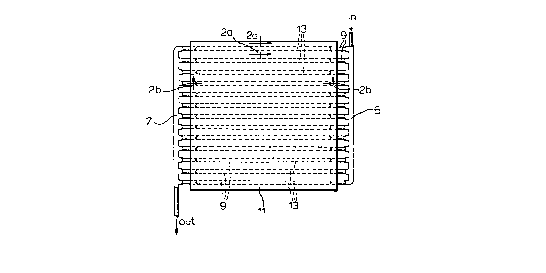
Figure l(b) shows a parallel flow liquid cooled heat sink according to the
present invention;
Figure 2(a) is a cross-section through the line 2A-2A in Figure l(b), showing
0 an insert according to the pr~fel I ed embodiment; and
Figure 2(b) is a cross-section through the line 2B-2B in Figure l(b), showing
the insert of the pl efe~ed embodiment.
Detailed Description of the Preferred Embodiment
With reference to Figure 1 (b), the heat sink of the present invention comprisesa front end header 5, a rear end header 7, a plurality of parallel tube channels 9
connected to the headers 5 and 7 and housed within a thermally conductive block 11.
A plurality of heat generating electronic components are arranged on the
2 o surface of thermally conductive block 11 so that liquid flowing through the parallel
paths or tube channels 9 absorbs the heat in accordance with standard heat exchange
principles. As indicated above, according to the present invention, each parallel tube
9 is preferably provided with an insert or accelerator 13 for blocking part of the fluid
flow and thereby increasing fluid velocity within the channel tube 9.
2 5 Turning to Figures 2(a) and 2(b), the channel tube 9 is shown disposed within
thermally conductive block 11. A surface 15 of the block 11 is in contact with aplurality of heat generating electronic devices, shown schematically in Figures 2(a)
and 2(b) by reference numeral 15. Preferably, the block 11 is an al~minurn block into
which copper tube 9 is inserted and expanded using conventional techniques.
3 o The insert l 3 is shown as being of generally cylindrical shape and is secured
within the copper tube 9 via interference fit by means of a plurality of ribs 19.
Opposite ends 21 of the insert 13 are preferably of conical shape. The insert 13 may

CA 02203213 1997-04-21
be fabricated from plastic or other suitable material.
In operation, the insert 13 causes fluid flow to accelerate around an annulus
between the inside surface 23 of the copper tube and the outside of the insert or
accelerator 13, thereby increasing the velocity of fluid flow. Therefore, considered
one way, by keeping a constant di~rneter oftube 9, the provision of insert 13 increases
the velocity of fluid flow, thereby enhancing the heat ~ s~er characteristics relative
to a tube of similar diameter without an insert. Or, considered another way, by
enlarging the diameter of the copper tube 9, and providing insert 13 to m~int~in a
fluid flow which is similar to the fluid flow of a smaller diameter tube without an
insert, the heat transfer surface area is thereby increased, thus improving overall
thermal performance.
Studies have been conducted to identify the benefits of the insert 13 relative to
the diameter of copper tube 9. These studies have shown that, for a constant
volumetric flow rate, constant channel diameter (D) of the tube 9, a smooth channel
surface, and a correlation for friction factor in the range of 4000<Reynolds
no.<200000 utilized for head loss calculations, increases in average velocity of fluid
flow and conductances are observed for different insert diameters (X). Table 1 shows
increases in velocity, conductance and head loss for dirrel en~ ratios of insert diameter
(X) to channel diameter (1~), from which it is evident that a 0.5 insert is feasible with
2 o a trade off of 326% increase in head loss for a 30% gain in conduct~nce.
Table 1: Effect to Insert Due To Increase In Velocity
Increase In
X/D Velocity Conduct~nce Head Loss
0.5 1.33 1.31 4.26
0.7 1.96 1.71 15.8
As discussed above, the insert 13 may also be used to increase the surface area
3 0 of heat transfer by enlarging the channel diameter and n~ in; l~g the same average
velocity as would characterize a lesser diameter channel. An analytical investigation
has been conducted to study this aspect of operation, based on the following

CA 02203213 1997-04-21
assumptions: constant volumetric flow rate, constant cross-sectional flow area
(m~int~ined constant by enlarging the channel fli~met~r (D) and choosing an
approp,ia~e insert di~meter (X)), smooth channel surface, and correlation for the
friction factor in the range 4000<Reynolds no.C200000 for head loss calculations.
5 The results of this investigation are reproduced in Table 2.
Table 2: Effect of Insert Due To Increase in Surface Area
Increase In
X/DDiameter Conductance Head Loss
0.5 l.lS 1.21 1.96
0.7 1.40 1.44 2.90
Table 2 illustrates that ~ltili7.ing insert 13 for the sake of increasing the surface
area and keeping the flow rate the same as would be provided with a lesser diameter
tube ch~nnel, results in less significant head loss increases than shown in Table 1.
Table 2 implies that by increasing the chaMel diameter (D) to 1.4 times its original
diameter and incorporating a 0.7 insert, a 44% increase in conductance can be
2 o realized compro"~ised by a 190% increase in head loss.
From the fo~egoing studies, it is appale"l that for an insert 13 having a cross-sectional area which is approximately half that of the cross-sectional area of the tube
9, significant gains are obtained. In practice, the cross-sectional area of the insert will
be application specific, depending on the number of parallel ch~nnels and the pump
2 5 capacity.
According to a successful prototype of the invention, the thickness of tube 9 is0.049 inches, the diameter of insert 13 is 0.342 inches, the diameter oftube channel 9
is 0.521 inches and the thickness of each rib 19 is 0.040 inches. This results in a
cross-sectional area of the insert 13 being 0.1062in2 and a cross-sectional area of the
tube 9 being 0.2132in~.
The preîer,ed length ofthe insert 13 within channel tube 9 is equal to the

CA 02203213 1997-04-21
length of the conductive block 11 parallel to the tube(s) 9, although for m~mlf~ctllring
reasons the insert may in fact be approximately 2" shorter than the imbedded tube 9,
approximately 1" set back from each end.
Other embodiments and variations of the invention are contemplated. For
example, in some circ~m~t~nce~, in addition to the parallel tube c.h~nnels 9, it may be
desirable to have one or more series connected pipes, depending on the configuration
of heat generating elements to be connected to the heat sink. Also, there may beapplications in which an insert is not required in each tube 9. Furthermore, the inside
surface 23 of the tube 9 may be scribed or grooved to receive the fins 19 to enhance
0 the interference fit.
All such embodiments or variations are believed to be within the sphere and
scope of the present invention as defined by the claims appended hereto.

Dessin représentatif
Une figure unique qui représente un dessin illustrant l'invention.
États administratifs

2024-08-01 : Dans le cadre de la transition vers les Brevets de nouvelle génération (BNG), la base de données sur les brevets canadiens (BDBC) contient désormais un Historique d'événement plus détaillé, qui reproduit le Journal des événements de notre nouvelle solution interne.

Veuillez noter que les événements débutant par « Inactive : » se réfèrent à des événements qui ne sont plus utilisés dans notre nouvelle solution interne.

Pour une meilleure compréhension de l'état de la demande ou brevet qui figure sur cette page, la rubrique Mise en garde , et les descriptions de Brevet , Historique d'événement , Taxes périodiques et Historique des paiements devraient être consultées.

Historique d'événement

Description Date
Inactive : CIB de MCD 2006-03-12
Inactive : Lettre officielle 2004-03-23
Inactive : Inventeur supprimé 2000-07-05
Le délai pour l'annulation est expiré 2000-04-25
Demande non rétablie avant l'échéance 2000-04-25
Réputée abandonnée - omission de répondre à un avis sur les taxes pour le maintien en état 1999-04-21
Demande publiée (accessible au public) 1997-11-30
Inactive : CIB attribuée 1997-07-30
Inactive : CIB en 1re position 1997-07-30
Inactive : Certificat de dépôt - Sans RE (Anglais) 1997-07-17
Exigences de dépôt - jugé conforme 1997-07-17
Lettre envoyée 1997-07-17

Historique d'abandonnement

Date d'abandonnement Raison Date de rétablissement
1999-04-21

Historique des taxes

Type de taxes Anniversaire Échéance Date payée
Taxe pour le dépôt - générale 1997-04-21
Enregistrement d'un document 1997-04-21
Titulaires au dossier

Les titulaires actuels et antérieures au dossier sont affichés en ordre alphabétique.

Titulaires actuels au dossier
R-THETA INC.
Titulaires antérieures au dossier
DAVID W. FAST
DEO RAMPERSAUD
JAMES R.S. BUTLER
MARIO J. CHILANSKI
MICHAEL RADOSEVIC
Les propriétaires antérieurs qui ne figurent pas dans la liste des « Propriétaires au dossier » apparaîtront dans d'autres documents au dossier.
Documents

Pour visionner les fichiers sélectionnés, entrer le code reCAPTCHA :


Pour visualiser une image, cliquer sur un lien dans la colonne description du document. Pour télécharger l'image (les images), cliquer l'une ou plusieurs cases à cocher dans la première colonne et ensuite cliquer sur le bouton "Télécharger sélection en format PDF (archive Zip)" ou le bouton "Télécharger sélection (en un fichier PDF fusionné)".

Liste des documents de brevet publiés et non publiés sur la BDBC .

Si vous avez des difficultés à accéder au contenu, veuillez communiquer avec le Centre de services à la clientèle au 1-866-997-1936, ou envoyer un courriel au Centre de service à la clientèle de l'OPIC.


Description du
Document 
Date
(aaaa-mm-jj) 
Nombre de pages   Taille de l'image (Ko) 
Abrégé 1997-04-21 1 21
Description 1997-04-21 5 200
Dessins 1997-04-21 2 50
Revendications 1997-04-21 2 53
Page couverture 1998-02-03 1 52
Dessin représentatif 1998-02-03 1 8
Courtoisie - Certificat d'enregistrement (document(s) connexe(s)) 1997-07-17 1 118
Certificat de dépôt (anglais) 1997-07-17 1 165
Rappel de taxe de maintien due 1998-12-22 1 110
Courtoisie - Lettre d'abandon (taxe de maintien en état) 1999-05-19 1 186
Correspondance 2004-03-23 1 18