Note: Descriptions are shown in the official language in which they were submitted.
CA 02203224 l997-0~-2l
Description
DISPENSER FOR CANDIES OR THE LIKE
Technical Field
This invention relates to a dispenser for candy pellets or
the like and, more particularly, to such a dispenser in which
individual pellets are forcibly propelled from the dispenser
by a lever spring biased by a J-shaped leaf spring.
Background Information
Dispensers for pellet-like pieces of candy are well-known
and have been popular for a number of years. Such dispensers
allow the candy to be dispensed one piece at a time onto the
user's hand. Candy dispensers are disclosed in U.S. Patents
No. 3,515,111, granted June 2, 1970, to P. Auge; No. 4,589,575,
granted May 20, 1986, to A. Rigberg et al.; No. 4,966,305,
granted October 30, 1990, to I. Hinterreiter; and No.
5,178,298, granted January 12, 1993, to C. J. Allina.
Dispensers for dispensing pills or tablets are disclosed by
U.S. Patents No. 2,705,576, granted April 5, 1955, to A. F.
Amelio et al. and No. 3,270,915, granted September 6, 1966, to
J. R. Auer. U.S. Patent No. 3,422,991, granted January 21,
1969, to I. C. MacDougall et al., discloses a dispenser for
heat accumulative pellets.
Summary of the Invention
The present invention is directed toward a dispenser for
pellets. According to an aspect of the invention, the
dispenser comprises a body lncluding a compartment configured
to receive a stack of pellets, and a dispensing slot located
at one end of the compartment and having a side opening. A
spring is positioned to bias the stack toward said one end of
the compartment. A dispensing lever has a rest position and
a cocked position. In the rest position, the lever is
substantially in the slot and adjacent to the side opening and
acts against the force of the spring to block movement of the
pellets into the slot. In the cocked position, the lever is
CA 02203224 1997-0~-21
moved away from the side opening to allow one of the pellets
to move into a dispensing position in the slot and adjacent to
the side opening. The lever is mounted on the body to pivot
about a pivot axis between the rest position and the cocked
position. A substantially ~-shaped leaf spring is positioned
to bias the lever into its rest position. The leaf spring has
a curved end secured to the lever and arcing around the axis,
and an opposite end. A stop is carried by the body and is
positioned to engage the opposite end of the leaf spring when
the lever is pivoted from its rest position to its cocked
position. This allows the opposite end of the leaf spring to
move linearly toward the axis but prevents the opposite end
from pivoting about the axis. When the lever is released from
its cocked position, the leaf spring moves the lever into its
rest position to propel a pellet in the slot out of the
dispenser through the side opening.
Preferably, the curved end of the leaf spring is secured
to an end portion of the lever, and the curved end and the
lever end portion together form an end member. The dispenser
further comprises a stop pin projecting into the slot and
positioned to engage the end member to limit movement of the
lever toward its cocked position and arcing of the curved end
of the leaf spring around the axis. Also preferably, the lever
includes a notch positioned adjacent to the axis to receive the
stop pin when the lever moves toward the rest position.
Another preferred feature of the invention is a stop post
extending across an end of the slot opposite the pivot axis.
The stop post is positioned to engage the lever to limit
movement of the lever toward its rest position.
30In the preferred embodiment, the stop for the opposite end
of the leaf spring projects into the slot adjacent to the
opposite end. In its rest position, the lever is substantially
parallel to the spring's opposite end. The lever slides
between the end of the compartment adjacent to the slot and the
opposite end of the leaf spring when it pivots from its rest
position to its cocked position.
CA 02203224 1997-0~-21
The structure of the body of the dispenser may be varied.
In the preferred embodiment, the body includes an inner shell
and an outer sleeve. The inner shell receives the stack of
pellets. The shell has a first end portion adjacent to the
slot, a base that defines and closes an end of the compartment
opposite the slot, and an open side. The outer sleeve is
slidable on the shell to expose and cover the open side. The
base has a pair of notches adjacent to the open side. The
shell has a pair of elongated ribs positioned to slide in the
pair of notches when the sleeve slides relative to the shell.
The parts of the dispenser may be made from a variety of
materials. In the preferred form, the J-shaped leaf spring and
the lever are made from molded plastic.
The invention provides a design for a dispenser that is an
improvement over the previously known designs. The dispenser
of the invention has a number of advantages. These advantages
include economy of manufacture, durability, and reliability in
operation. They also include the capability of being embodied
in a dispenser having an attractive appearance.
These and other advantages and features will become
apparent from the detailed description of the best mode for
carrying out the invention that follows.
Brief Description of the Drawinqs
In the drawings, like element designations refer to like
parts throughout, and:
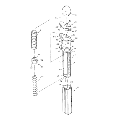
Fig. 1 is an exploded pictorial view of the preferred
embodiment of the dispenser and a plurality of pellets.
Fig. 2 is an assembled sectional view of the dispenser and
pellets shown in Fig. 1, with parts shown in elevation.
Fig. 3 is a pictorial view of the dispenser shown in Figs.
1 and 2 illustrating the lever in a cocked position.
Fig. 4 is like Fig. 3 except that it shows the lever after
it has been released and has propelled a pellet out from the
dispenser.
Fig. 5 is a front elevational view of the top portion of
the dispenser shown in Figs. 1-4.
CA 02203224 1997-0~-21
Fig. 6 is a bottom plan view of the dispenser shown in
Figs. 1-5.
Fig. 7 is a rear elevational view of the top portion of the
dispenser shown in Figs. 1-6 illustrating the lever in its rest
position.
Fig. 8 is like Fig. 7 except that it shows the lever in its
cocked position.
Best Mode for Carryinq out the Invention
The drawings show a dispenser 2 that is constructed
according to the invention and that constitutes the best mode
for carrying out the invention currently known to the
applicant. The dispenser of the invention is intended
primarily for dispensing pieces P of candy and for use by
children. However, the dispenser may also be used for
dispensing other types of pellets, including but not limited
to pills and tablets, and may be used by adults as well as
children. As shown in the drawings, the dispenser 2 has a body
on which a head H is mounted. The head H is shown in a generic
form. It is anticipated that, in actual use, the dispenser 2
will include a head that is attractive to children, such as a
head representing a popular fictional character.
Referring to Figs. 1 and 2, the dispenser body includes an
inner shell 4 and an outer sleeve 20. The shell 4 has a
U-shaped cross section. An elongated upper flange 6 is mounted
on a first open end of the shell 4. The flange 6 includes a
first large side projection 8 and a second opposite smaller
side projection 9. These projections 8, 9 serve as mounting
portions, as described further below. The flange 6 also has
a center circular opening 7 extending therethrough in alignment
with the space defined by the shell 4. The opening 7 is
configured and dimensioned to be slightly larger than a round
pellet P of candy for which the illustrated embodiment is
designed. The cross section of the shell 4 and the shape and
size of the opening 7 may be modified to accommodate other
sizes and configurations of pellets without departing from the
spirit and scope of the invention.
CA 02203224 l997-0~-2l
The end of the inner shell 4 opposite the flange 6 iS
closed by an end wall 10. A spring post 12 extends from a
sidewall of the shell 4 parallel to and spaced a small distance
above the end wall 10. The post 12 extends toward the open
side 14 of the U-shaped shell 4. Its attached end is
positioned adjacent to the base of a longitudinal slot 16 that
extends along the sidewall of the shell 4 opposite the open
side 14 upwardly to a location proximate to but spaced from the
flange 6. The end wall 10 has a pair of small notches 18
extending therethrough adjacent to the open side 14. These
notches 18 engage ribs 26 on the outer sleeve 20, as shown in
Fig. 6 and described further below.
The outer sleeve 20 iS slidable on the shell 4 to expose
and cover the open side 14 of the shell 4. To accommodate the
shell 4, the sleeve 20 has a cross section complementary to the
shell's cross section. The sleeve cross section has a closed
side opposite its U-shaped portion to completely enclose the
shell 4 and cover the open side 14 when the dispenser is in the
closed use position shown in Figs. 2-4. -Each of the opposite
ends of the sleeve 20 are open. First and second opposite
elongated channels 22, 24 extend along inner wall surfaces of
the sleeve 20. Each channel 22, 24 extends from an open
bottom, shown in Fig. 6, to a closed upper end. The first
channel 22 iS positioned to be adjacent to the open side 14 of
the shell 4 when the dispenser 2 iS assembled into its use
position. The second channel 24 iS opposite to and confronts
the first channel 22 and extends along the curved apex of the
U-shaped portion of the sleeve sidewall.
The ribs 26 mentioned above extend longitudinally along the
inner surface of the sleeve 20 at the opposite edges of the
first channel 22. The ribs 26 have a limited height, for
example about .10 centimeters, and are received in the
correspondingly shallow notches 18 on the end wall 10 of the
shell 4. The engagement of the ribs 26 in the notches 18
guides sliding movement of the sleeve 20 relative to the shell
4 and helps assure that such movement is smooth to facilitate
loading the dispenser 2 with candy pellets P. The ribs 26 also
CA 02203224 l997-0~-2l
increase the effective depth of the channel 22 and help to
retain the stack of pellets P in position closely adjacent to
the curved apex of the U-shaped portion of the sleeve sidewall.
The dispenser 2 includes a slidable cup-shaped spring
abutment 30. The abutment 30 is received into the inner shell
4. A first substantially rectangular side projection 32 on the
abutment 30 iS positioned to extend radially through the open
side 14 and into the first channel 22 on the inner surface of
the outer sleeve 20. A second side projection 34 opposite the
first projection 32 iS positioned to extend radially through
the longitudinal slot 16 in the shell 4 and into the second
channel 24 of the outer sleeve 20. The second projection 34
has a radial extent greater than that of the first projection
32 and terminates in an outer end surface that tapers radially
inwardly and downwardly. The tapered surface facilitates
assembly of the dispenser 2. Engagement of the projections 32,
34 with the closed upper ends of the channels 22, 24 limits
movement of the abutment 30 relative to the sleeve 20 to
prevent passage of the abutment 30 out of the shell 4 through
the center opening 7 in the upper flange 6 and to retain the
abutment 30 in a position substantially within the sleeve 20.
Sliding movement of the projections 32, 34 in the slot 16 and
channels 22, 24 guides movement of the abutment 30 relative to
the shell 4 and helps prevent tilting of the abutment 30. The
abutment 30 has an upper support surface 36 configured to
support a stack of pellets P, as shown in Fig. 2. The surface
36 and the diameter of the abutment 30 are designed to be
slightly smaller than the opening 7 to permit the surface 36
to move upwardly into a position substantially flush with the
top surface of the flange 6.
A coil spring 40 is positioned in the shell 4 to bias the
abutment 30 upwardly toward the flange 6. The lower end of the
spring 40 is hooked around the free end of the spring post 12
to anchor the spring 40. The opposite end of the spring 40
extends into the cup-shaped abutment 30. Thus, the end wall
10/spring post 12 and the inner bottom surface of the
cup-shaped abutment 30 serve as abutments for the opposite ends
CA 02203224 l997-0~-2l
of the spring 40. Movement of the sleeve 20 downwardly
relative to the shell 4 and away from the upper flange 6
compresses the spring 40 between its opposite abutments and
exposes the open side 14 of the shell 4.
To load the dispenser 2, the sleeve 20 iS moved downwardly
relative to the shell 4 as far as it will go. This compresses
the spring 40 and exposes the open side 14 of the shell 4.
Then, a stack of pellets P is inserted into the shell 4 through
the open side 14. Once the pellets P are positioned, the shell
4 and sleeve 20 are manually returned to their use positions
shown in Figs. 2-4. In this position, the shell 4 and the
sidewall of the sleeve 20 adjacent to the shell's open side 14
together form a compartment C configured to receive and retain
a stack of pellets P. The flange 6 iS positioned at and
partially defines the top of the compartment C.
The body of the dispenser 2 further includes a top plate
44 having essentially the same plan form as the upper flange
6 except for the absence of a center opening. The top plate
44 iS mounted on and spaced above the flange 6 in parallel
alignment therewith so that a dispensing slot S is defined
therebetween. The slot S has a height slightly greater than
the thickness of-an individual pellet. Preferably, the upper
surface of the plate 44 has a mounting stud 46 formed thereon
for mounting a head H on the dispenser body. A pivot post 48
defining a pivot axis X extends downwardly from the larger side
projection of the plate 44 adjacent the end thereof toward the
flange 6. A reduced diameter end portion 78 of the post 48
forms a stud 78 that is received into a corresponding opening
80 in the flange 6 to form part of the attachment of the plate
44 to the flange 6.
Candy pellets P are dispensed from the dispenser 2 by means
of a lever 50. The lever 50 has a first pivot end 52 that is
pivotably attached to the pivot post 48 to pivotably mount the
lever 50 on the dispenser body. The lever 50 iS a
substantiaIly flat thin member with an enlarged attachment
portion 54 formed on the pivot end 52. The attachment portion
54 extends perpendicularly beyond the plane of the main flat
CA 02203224 l997-0~-2l
portion of the lever 50. The flat lever body also includes a
laterally enlarged center portion 56 and a reduced width
actuator end 58 opposite the pivot end 52. The actuator end
58 extends out of the slot S and beyond the body of the
dispenser 2 to permit engagement by the thumb or finger of the
user of the dispenser 2.
The lever 50 has a rest position in which it is
substantially in the slot S and adjacent to a side opening of
the slot and acts against the force of the spring 40 to block
movement of candy pellets P into the slot S through the center
opening 7 in the upper flange 6. The lever 50 also has a
cocked position in which it is moved away from the side opening
of the slot S to allow one of the pellets P to move into a
dispensing position in the slot S adjacent to the slot's side
opening. The pivotable attachment of the pivot end 52 of the
lever 50 to the pivot post 48 mounts the lever 50 on the
dispenser body to pivot about the pivot axis X between the rest
position and the cocked position. The lever 50 iS spring
biased into its rest position. Figs. 4-7 illustrate the rest
position. Figs. 2, 3, and 8 illustrate the cocked position.
A stop post 60 extends across the end of the slot S
opposite the pivot axis X and is positioned to engage the
actuator end 58 of the lever 50 to limit movement of the lever
50 toward the rest position. As illustrated, the stop post 60
has a cylindrical configuration, but the configuration of the
post 50 may be varied without departing from the spirit and
scope of the invention. As shown in Fig. 1, a lower opening
82 iS formed in the bottom end of the stop post 60. This
opening 82 iS configured to receive a corresponding stud 84 on
the smaller side projection 9 of the flange 6. The engagement
of the stud 84 in the opening 82 cooperates with the engagement
of the extension 78 in the opening 80 to mount the top plate
44 onto the flange 6. Preferably, the connections are
reinforced by an adhesive.
The spring biasing of the lever 50 iS provided by a
J-shaped leaf spring 64. The spring 64 iS mounted
perpendicularly to and between the upper flange 6 and the top
CA 02203224 1997-0~-21
plate 44. A first curved end 66 of the spring 64 is secured
to the lever 50 and arcs around the pivot axis X. The straight
opposite end 68 of the spring 64 extends along a side edge
portion of the slot S opposite the open side of the slot S and
toward the stop post 60. A rectangular stop 70 extends
downwardly from the undersurface of the top plate 44 into the
slot S adjacent to the outwardly facing flat surface of the
straight end 68 of the spring 64. The stop 70 is positioned
to engage the straight end 68 of the spring 64 when the lever
50 is pivoted by a user from its rest position to its cocked
position. The engagement of the spring end 68 by the stop 70
allows the end 68 to move linearly toward the axis X but
prevents the end 68 from pivoting about the axis X. See Figs.
7 and 8. Limiting the spring end 68 to translating movement
causes the degree to which the curved end 66 arcs around the
axis X to increase to store energy in the spring 64.
When the lever 50 is released from its cocked position, the
stored energy in the spring 64 moves the lever 50 back into its
rest position. Movement of the lever 50 into the rest position
causes the lever 50 to engage the pellet P that moved up into
the slot S upon cocking of the lever 50. The spring action of
the lever 50 results in sudden engagement of the pellet P by
the lever 50 to propel the pellet P out of the dispenser 2
through the side opening of the slot S, as illustrated in Fig.
4. The pellet P may be dispensed into the user's or another's
hand or directly into the user's mouth. Therefore, the
dispenser 2 can be operated using only one hand.
As noted above, the curved end 66 of the leaf spring 64 is
secured to the lever 50. In the illustrated preferred
embodiment, the outer edge of the curved end 66 is secured to
the attachment portion 54 of the lever 50. The curved end 66
and attachment portion 54 together form an end member. The
dispenser 2 further includes a stop pin 74 projecting upwardly
into the slot S from the flange 6. The stop pin 74 is
positioned to engage the end member 54, 66 to limit movement
of the lever 50 toward the cocked position and also limit
arcing of the curved end 66 of the spring 64 around the axis
CA 02203224 1997-0~-21
X. As shown, the attachment portion 54 in effect forms a
continuation of the arcing of the curved end 66 about the axis
X, and the edge of the attachment portion 54 opposite the
attachment to the spring's curved end 66 directly engages the
stop pin 74. Preferably, the lever 50 includes a notch 76
positioned adjacent to the axis X to receive the stop pin 74
when the lever 50 moves toward its rest positioh.
In its rest position, the lever 50 extends through the slot
S substantially parallel to the straight end 68 of the spring
64. As the lever 50 pivots about its axis X, it slides between
the upper flange 6 and the straight end 68 of the spring 64.
This arrangement positions the center portion 56 of the lever
50 closely adjacent to the flange center opening 7 to
effectively block movement of pellets P into the slot S when
the lever 50 iS in its rest position. At the same time, the
thickness of the lever is maintained at a fraction of the
thickness of an individual pellet P. When the lever 50 iS in
its rest position, the edge,of the lever 50 opposite the open
side of the slot S is substantially flush with the flat
perpendicular surface of the straight end 68 of the spring 64
to provide a compact structure and neat appearance. The lever
50 and spring 64 in effect close the rear side of the slot S
opposite the open side.
The various parts of the dispenser 2 may be made from
various materials. However, the parts of the dispenser 2, with
the exception of the spring 40, are preferably made from molded
plastic. The dispenser body is preferably three pieces of
molded plastic assembled together. The first piece includes
the inner shell 4 integrally molded with the upper flange 6.
The second piece is the outer sleeve 20. The third piece is
the top plate 44. The spring 40 in the preferred embodiment
is an ordinary metal coil spring. The J-shaped leaf spring 64
and the lever 50 are also each preferably made from molded
plastic. The attachment of the curved end 66 of the spring 64
to the lever 50 may be accomplished by an adhesive or some
other known bonding procedure. Alternatively, the spring 64
and the lever 50 may be integrally molded as a single piece.
CA 02203224 1997-0~-21
Suitable materials for the spring 64 include polycarbonate,
high impact polystyrene, and ABS (acrylonitrile butadiene
styrene) resin.
As used herein, the terms "upwardly", "downwardly", and the
like refer to the use position illustrated in Figs. 2-4. The
terms are used to facilitate description of the invention and
are not intended to limit the scope of the invention or to
limit the dispenser to any particular orientation.
Although the preferred embodiment of the invention has been
illustrated and described herein, it is intended to be
understood by those skilled in the art that various
modifications and omissions in form and detail may be made
without departing from the spirit and scope of the invention
as defined by the following claims.