Note: Descriptions are shown in the official language in which they were submitted.
2.0194-001 CA 02203~90 1997-04-24
ALU~NOUS PRESS PLATE AND
PROCESS FOR PRODUCrNG SAME
BACKGROUND OF Il~l~TION
1. Field of the Invention
The p.~senl invention relates to l-q-m. inq~ted aluminum/aluminum
alloy based press plates used in heat and prcssure applications to manufacture
decorative laminates and, more particularly, to an improved prcss plate
comprised of an aluminous alloy core plate and an anodi7ed buffed or textured
aluminum cladding layer that enables the production of decorative lqminq~tes
having high quality scratch, mar, scrape and abrasive wear reci~tqnt surfaces,
and also to a method for manufacturing the press plates.
2. Description of the Prior Art
Decorative lqmin~q,te manufacture and their uses are well known by
those versed in the art. They are used extensively for many varied surfacing
(and related structural) applications in the commercial, institutional and
residential sectors, where pleasing aesthetics, durability, cleqnqbility, and other
unique properties are desired. For example, decorative lqminq~tes are
particularly well suited for residential, il~alitulional and office rulllilu~, kitchen
countertops, bathroom vanities, cabinets, wall pAneling~ doors, direct
application flooring and computer room access floor tiles, co~ ler work
station and electronic componelll assembly station tops, laboratory bench tops,
toilet partitions and many other applications where, besides their inherent
CA 02203~90 1997-04-24
20194-001
decorative appeal, special enhanced l~ro~ lies such as postformability, fire
retardency, wear resict~nce, electrostatic dissipativity, harsh chemical stain
resistance, in-use abuse resist~nce and physical strength are required.
Decorative l~min~tes can be conveniently divided into two general
5 categories, viz. high pressure decorative l~min~te and low p.~,ssure dccola~ e
laminate, based on the distinctive and often unique comp~sitions, processes,
properties, and thus applications, of each type. High pressure decorative
laminates are more suited to "high use and abuse" applications, particularly
where "cold" bendability or heat induced postformability is needed, such as
10 horizontal work and service surfaces, and floor tiles, whcre their generally
superior wear resistance and impact resistance pro~llies are beneficial. Low
pressure decorative laminates are most useful for low wear and vertical
surfacing applications, particularly where ease of fabrication and assembly are
important considerations, such as cabinets and wall panels. However, such
15 applications as noted above are not mutually exclusive in that, for example,
high pressure decorative l~rnin~tes are commonly used for cabinet faces and
linings, and low pressure decorative laminates are commonly used for
horizontal as wdl as vertical surfaces (and for structural su~Gll) in, for
example, "knock down" and other low cost rul,.il~r~. A particular article
20 manufacturer may advantageously use bo~h together, such as an office desk
with a high pressure decorative lamin~te top and low pressure decorative
laminate pedest~ls and modesty panel.
20194-001 CA 02203~90 1997-04-24
High pressure decorative laminates, as the name implies, are
produced using relatively high pressures, usually 1,000 psig. or more in a
heated flat bed hydraulic press, to achieve the requisite resin flow, cure and
consolidation of the various composite layers (or l~min~e) into a unified
S l~minated assembly. The lamin~te is typically comprised of a plurity of filler
or core sheets (plies) most commonly cGn~posed of kraft paper i,l,~rcgnated
with a phenol-formaldehyde thermosetting polymer (a;k.a. phenolic resin). The
paper and/or phenolic resin used can be modified to impart spccific desired
properties to the final laminate. For example, the phenolic resin can be
10 modified with a plasticizer to improve postformability, or either the kraft paper
or phenolic resin can be modified with non-flammable salts or other additives
to enhance fire retardency. In addition, other phenol based co",pounds and
aldehydes may be used to alter the ~rope.lies of the basic resin. On top of the
filler plies are placed one or more decorativc surface sheets, which are most
15 commonly comprised of highly refined alpha-cellulose papers treated with a
melamine-formaldehyde thermosettinp polymer (a.k.a. m~l~mine resin). Again,
the papers and/or melamine resin can be modified to promote certain desired
laminate properties. For example, the papers may contain a portion of cotton
linter fibers or hard abrasive grit particles to improve posll~"~ability or wear
20 resistance propenies ~es~ctively; similarly the resin may be modified with
plasticizers such as o,p-toluene sulfonamide or various glycols, or with abrasive
grit, to also enhance postforrning or wear l,ropc.lies respectively. In addition,
20194-001 CA 02203590 1997-04-24
- 4 -
other amines, such as acetoquanamine or urea may be advantageously used in
the resin formulation, as can other aldehydes. Further, polyhydroxyl
compounds, such as various sugars, havc bcen used to modify the basic
melamine resin, and a variety of catalysts (usually acids or acid g,tnc.~ling salts
such as organic or inorganic acid/amine salts) and press platc releasc agents
(typically fatty acid salt types) are generally added to the me.l~mine surface
resin as well to improve processing and control final i~min~te l.ro~lLies. The
laminate surface construction typically consists of a single ply of a pigmented
and highly filled paper (with opacifiers such as TiO2 and clay) in the case of
solid color papers, or a ply of pigmented and filled paper on which is
rotogravure or otherwise printed on its ~ ost surface a ~attc~" or design
(commonly termed a "print sheetn), and over which is placed a light weight (40
g.s.m. or less) natural or tinted color low opacity papcr to protect the print ink
line (commonly termed an "overlay"), which when p,cssed, becomes cssenti~lly
translucent thus allowing the pattern bcllc?ltl~ to be visible, and forms the top
most surface of the resultant l~minate. In the case of solid colors, thc top most
surface of the l~min~te is usually the solid color dccG~aL~e paper itself,
although for special applications, an overlay may also be uscd in conjunction
with it.
Conversely, low pressure dccGlali~c l~min~cs are produce~ in a
heated flat bed hydraulic press at significantly lower pressures of about 300
psig, and higher cure te"~eratllres, generally using very short cycle times and
CA 02203~90 1997-04-24
20194-001
- 5 -
hot discharge from the press thereafter. The core of the l~min~te, or substrate,
usually consists of a single unified board, such as wood based particleboard or
medium density fiberboard (MDF), although other types of boards, e.g. cement
fiber board, may be used for specific applications. The surfaces of the board,
5 typically particleboard or MDF board, are covered with one or more plies of
melamine resin impregnated decorative papers. Normally, a single ply of solid
color or print paper (without an overlay) is used to surface each face of the
board, to "balance" the board and prevent the l~min~te from warping, although
overlay and other combinations of surface papers may be used for specific
10 purposes. The composition of the decorative surface papers are essentially the
same as those for high pressure decG,alive l~rnin~tes, although specific
properties such as basis weight, l~o,osity, density and pH may be altered
somewhat to improve processing. The generic term "mel~rnine resin" applies
in much the same way as for high pressure decG.ali~e l~min~te, in as much as
15 the basic resin may be modified with copolymers, plasticizers, catalysts, release
agents, grit, and numerous other re~ ntC and additives to improve l~min~te
processing and/or its propel ties. Normally, the basic surface resin is the
melamine resin type, although urea-forrn~ldellyde resin, either discreetly, or in
combination with the mel~mine resin, may be used to advantage. To facilitate
20 resin flow and cure, and as such, bonding of the decordti~e sheets to the board
during the very short, low pressure, high te",~,at.lre press cycles normally
employed, the surface resins are usually considçrably more plasticized (as flow
20194-~1 CA 02203~90 1997-04-24
- 6 -
promoters) snd catalyzed, than the high pressure decorative l~min~te
counterparts. The short cycle times are desirable not only for productivity
considerations, but to avoid excessive heating of the substrate board itself,
which can cause blistering and even violent "explosion" of the board during
5 pressure release and hot discharge from the press due to rapid vol~tili7~tion of
moisture trapped, until that point, within the board.
Those versed in the art will appreciate that the papcr technology
and resin chemistry associated with manufacture of high prcs~ure and low
pressure decorative laminates contained herein is not inclusivc and eYh~l1stive,
10 but is intended only to be generally descriptive. Spccific descriptions of the
high pressure and low pressure decorative l~minsting processes, and the
equipment employed in each, are discussed in more detail below.
The manufacture of decorative lAmin~t~ has undcigonc a series of
innovations which have led to greater and glcalcr con~urner e,~l~.t~l;ons
15 regarding decorative l~min~te durability and resict~nc~ to mar, scratch, scrape
and abrasion damage. Efforts to produce such wcar resist~nt decorati~/e
laminate, especi~lly high prcssure dccG~aL~e ~ infitÇ, have jnrl~ded a variety
of means to produce a hard surface that resists degradation from physical
abrasion, etc. For example, hard alumina grits of varying sizcs havc been
20 incorporated within the l~min~tç surface to improvc product durability.
However, the use of alumina grit to improve thc wcar resistancc of dccorativc
laminate, even in small grit sizes and concenl,ations, destroys the surface
CA 02203~90 1997-04-24
20194-001
microfinish of conventional stainless steel press plates heretofore employed to
fabricate decorative laminates.
The physical interaction of the formulation grit and the surface of
the press plate causes microsratching and resulting lowcr gloss, h~7iness, "soft
S glow" high spot texture wear, and at times metal rub-off. rullhcl, as the
surface finish of the press plate imparts its overall surface finish to the final
laminate product, for example, to form a high gloss or textured surface finish
on the decorative laminate, substantial marring of the surface microfinish of the
press plate renders the press plate unusable and often requires the damaged
10 press plate to be refurbished at considerable expense or ultimately scrapped.
Conventional buffed stainless steel press plates normally suffer ur~ ceptably
severe microscratching in as little use as just one press run with cven relatively
small size alumina grit. Textured stainless steel press plates are also easily
microscratched by alumina grit. Although not as visually app~enl as with
15 highly buffed plates bec~use of their generally much lower initial gloss level
and inherent texture structure, the result~nt gradual deterioration in gloss and
texture erosion, particularly with usc of larger grit sizes and conce~ ations,
necessitates frequent refiniching.
Chrome plated steel press plates also suffer from severe
20 microscratching after relatively fcw pressings. Chrome plating and post-baked
electroless nickel deposition on st~intgss steel plates have been used, yet do not
satisfactorily resolve the problems of grit-related microscr~tching and plate
20194-001 CA 02203~90 1997-04-24
wear. Further, buffing operations used for high gloss plates, or shot-blasting
refinishing operations used for textured plates, tend to remove the thin plated
layer unevenly, c~ncing considerable cost to strip and re-plate the surface. The
trend towards greater conccnllaLions of even larger sized grit formulations only
5 exacerbates these problems.
Press plates used to produce decorative lamin~tçs are somewhat
unique in overall geometry. Heretofore manufactured principally from various
grades of steel, particularly stainless steel, the press plate is a flat sheet of
rectangular cross-section having comparatively large longitu~lin~l and transverse
10 dimensions, for example, as large as 20 feet and 8 feet respectively. While the
press plates have opposing large planar surface arcas, they are typically only
about 1/8 of an inch thick, although they can vary in thickness from about 1/16
to 1/2 inch depending on their particular application.
When the press plate's planar surfaces are polishe~ and then
15 buffed to their final state, they ideally take on the a~xalance of a mirror-like
sheet. To obtain this required finish, microscopic surface discontinuities and
irregularities of any kind must be minimi7~. Minor impc.f,ctions in the
surface of the press platcs are lrallsl~rcd to the surfacc of the l~"~ during
pressing and curing operations and, thercfore, result in the production of
20 inferior or unacceptable glossy finish 1~rrin~te.
The terms polishing and buffing should be clarified, since there
are often misunderstandings between the deco.~dti~e l~in~ting and metal
CA 02203~90 1997-04-24
20194-001
g
surface finishing industries. Within the former, the two terms tend to be used
synonymously, and it is not uncommon to refer to Npolished" press plates,
which have in fact been subsequently buffed to a mirror-like finish, for the
manufacture of high gloss decorative l~min~tes, with their descriptive finish
S names including "polished", "glossyn, ~luster" and "lacquer". Howcver,
within the metal surface finishing industry, thcre is a marked distinction
between the two processes, as described in the American Society For Metals
(ASM) Metals Handbook (Ninth Edition, Volume 5, Surface Cle~ning,
Finishing and Coating, 1982, pages 107-116). Polishing, typically with
10 abrasive loaded endless cloth belts, is used to remove grinding lines, scratches,
pits, bumps and other surface defects. Often a series of abrasive belts,
proceeding from course grit to finer grits, are used, e.g. starting with 180 grit,
and in sequence, followed by 240, 320, and finally 400 grit polishing in
preparation for the final buffing operations.
After polishing to the desired smoothness, the surface can then be
buffed, normally using cloth disk wheel or "mopn ~cse-mblies in conjunction
with relatively fine abrasives, typically col"pounded in cm~lcifie~l fatty acid
"greases" or in solid, meltable waxes. There are two dictinct types of buffing.
In sequence, "hard buffing" with a fairly hard and rigid mop and mod~lately
20 aggressive compound or "rougeH is first used to remove residual polishing
marks and further smooth the surface. Finally, "color buffing", with a soft
"floppy" mop and very fine rouge is used to remove marks rem~ining after the
20194-001 CA 02203~90 1997-04-24
- 10 -
initial hard buff operation, resulting in a very smooth, scratch-free, high gloss
mirror-like finish.
Textured press plates are produced by nlecll~niç~lly shot peening,
mechanically embossing or chemically etching their planar surfaces, or
S combinations thereof, and are usually of much lower gloss than buffed press
plates. The laminate gloss level is directly related to the gloss of the press
plate from which it is produced. The greater the gloss of the plate, the greater
the gloss of the resultant laminate finish, and the more apparent plate wear
becomes on both.
In addition to being free of surface imperfections, the large planar
surfaces used to impart a surface finish to a cellulose suppGlled viscous resin
matrix must be free from warpage to the maximum extent possible. Warpage
generally takes two forms; the first is a regular bow appearing over the entire
longitudinal or transverse dimension. At modest levels, this bow is tolerable so
15 long as the press plate ~csumes a nearly perfect planar orientation under the
pressure of the press. The second type of warpage manifesls itself as loc~
distortions and buckling; the variations in the relative height of the press plate
being from a hypothetically perfect planar surface. This second type of
warpage is entirely objectionable as it often does not correct itself under the
20 pressure of the press and thus frequently results in defective l~min~te
appearance and scrapping of the press plate.
i
CA 02203~90 1997-04-24
20194-001
Thus, the level of manufacturing precision required to fabricate
and maintain an overall defect-free macrofinish and microfinish, and wa~p-free
surface, on both sides of the press plate, is critical. For c~ ple, for
production of high pressure decorative l~min~tes~ prcss plates are generally
5 used in a sandwich configuration with t vo co.,lposites of l~minste rcsin-
impregnated papers placed therebetween, facing oppositc directions with the
surfaces in contact with the plates. Multiple layers of interleaved l~min~tç
material and press plates, so called "packs" or "booksn, are then loaded into a
press for thermal curing and pressure treatment concQlid~tion. If either excess
10 ~arpage of the first type or any warpage of the second type exists in the press
plates, or if imperfections in the surface finish are ~,esent, significantly
deleterious defects in the resultant decorative laminatc appearance will be
apparent.
OB.~ECTS OF THE INVENl'ION
Accordingly, it is an object of this invention to provide a
hardened flat work piece, such as a press plate, for the economical production
of wear resistant decorative l~min~tes, where said decorative lamin~tes exhibit
improved resistance to scratch, mar, scrape and abrasion damagc.
It is a further object of this invention to provide a press plate for
20 the economical production of wear resistant deco-aliYe l~min~tes having a high-
quality microfinish of greatly extended press plate life.
CA 02203590 1997-04-24
201 94-001
It is also an object of this invention to provide a press plate free
of objectionable warpage for the economical production of wear resistant
decorative laminates.
It is another object of this invention to provide a method for
S producing an ~nodi7çd aluminum press plate offering si~nific~ntly ~ ater wear
life in the production of decorative l~min~tes.
Other objects, advantages, and features of the present invention
will be in part apparent and in part explained by reference to the following
detailed description and appended claims, and by ~fe~ence to the
accompanying drawings.
SI~IARY OF INVFl~TION
The presellt invention involves an alunlinum/aluminous alloy press
plate for producing decorative laminate sheets within a decorative l~rr in~te
press apparatus. The press plate comprises a subst~nt~ y flat core plate which
has opposed planar pressing surfaces of subst~nti~l area. The core plate is
composed of an aluminum alloy which has a 0.2% co~ essive yield stress, or
yield strength at 0.2% offset, of not less than about 180 MPa at 140~C. A
suitable core plate composition may be selectcd from eithcr the 2000 or 6000
series of aluminuln alloys set fonh in the American Society For Metals (ASM)
"Metals Handbook0" Desk Edition (1985) pages 6.8-6.11. Thesc aluminum
alloys contain suitable amounts of alloying elements which deliver the
necessary minimum co,.,pressi~/e yield stress pr~pc-lies.
CA 02203~90 1997-04-24
20194-001
- 13 -
Integrally bonded to the planar surfaces of the core plate is a
cladding of aluminum of not less then about 99% purity. Aluminurn or
aluminum alloys selected from the 1000 series set out in the ~fe,~nce text
noted above are suitable for use. The purity of the aluminum cl~Ain~ is
S significant because it makes possible achievcment of a high gloss surface finish
which is subst~nti~lly free of visible defects, including indications of grain
boundaries. Some of the core plate alloys suitable for use in this invention are
more prone to develop grain line defects during anodizing than others,
depending on the type and concenlration of alloying elements comprising the
10 specific alloy. The essentially pure aluminum cl~d~ling over the core plate
alloy obviates the problem of grain line defects associ~ted with any of the
selected core plate alloys of this invention, and as such, allows a broader
choice of alloys based on optimum desired mechanical propc.lies. On the
surface of the aluminum cladding there is provided, by mcans of an ~no ii7ing
lS process, a continuous film of alumina (Al203) which has a thickness ranging up
to about 50 microns. The alumina film is subsequently buffed by use of
suitable buffing equipment and buffing co."pound or "rouge" to provide the
desired mirror-like finish to the plate surface. The purity of the al~,...;n~,...
cl~d~iing is not as critical for textured plates, although selecte~ 1000 scries
20 materials are still l,refell~d. The relatively soft aluminum claddinE, con,yal~d
to the harder core plate alloy, facilitates mech~nical embossing of a texture
CA 02203~90 1997-04-24
20194-001
- 14 -
design into the plate surface. After the plate surface is textured by a suitablemethod, the surface is anodized as above.
The press plate of this invention is produced by providing an
aluminum alloy based core plate having the necess~ry composition to achieve a
0.2% compressive yield stress of not less then about 180 MPa at 140~C, and
then cladding the core plate with a layer of ah~mim)m of not lcss then about
99% purity. Bonding of the aluminum layer to the core plate is accomplished
by means of diffusion bonding, through the use of heat and ples~u.~
accompanying rolling of the mated materials. Aher the alllrninum is diffusion
bonded to the aluminum alloy base plate, and the plate surface subsequently
prepared with the desired finish or texture, the cl~dding layer is oxidi7ed, as by
anodizing, to provide an integral film of alumina ranging up to about 50
microns in thickness, and preferably in the range of from about 10 to 50
microns in thickness.
BRIEF DESCRIPTION OF T~ DRAWINGS
For a more complete underst~nding of this invention, r~fe.~nce is
made to the acco,-,~,anying drawings and following description. In the
drawings:
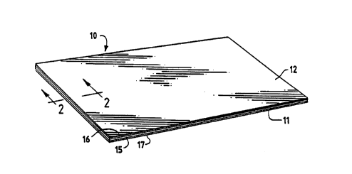
FIG. 1 is a ~,spective view of a typical press plate;
FIG. 2 is a sectional view taken along the line 2-2 of FIG. 1
through the alumina-aluminum-aluminous alloy-aluminum-alumina press plate
composite of this invention; and
20194-001 CA 02203590 1997-04-24
FIG. 3 is a side elevation of a portion of a representative high
pressure flat bed press and pack assembly, utilizing the press plates according
to the present invention.
DETAILED I)F-~CRIPTION OF THE p~2FFF~ n F~ OD~
Referring to FIG. 1 of thc drawings, thc press platc 10 of this
invention is substantially rectangular in shapc and has o~posed planar pressing
surfaces 11 and 12, which are of substantial area. The press platc comprises a
number of individual layers, specifically a core plate 15 and upper and lower
aluminum cl~dding layers 16 and 17, which form the cxposed planar surfaces
11 and 12. Referring to FIG. 2 of the drawings, the s~bstanlially flat core
plate 15 has opposed planar prcssing surfaccs of a substantial area, as
mentioned earlier. The core plate must be composed of an aluminum alloy
which exhibits a 0.2% co.,.l,ressive yield stress in excess of about 180 MPa at
140~C.
Alloys suitable for this purpose arc thosc selected from thc 2000
and 6000 series of alloys set forth in thc ASM Mctals Handbook0 Dcsk Edition
(1985). Such alloys include those shown below. Table I in~ic~tes their yield
strength at 0.2% offset, i.e. 0.2% compressivc yield strcss, at various
te"~peral~res. Table II shows the nominal elemental co."position of the alloys,
20 recognizing that in practice, certain elel,.ental concel~llation limits have been
established for each alloy.
CA 02203590 1997-04-24
20194-001
- 16-
TABLE I
Al ALLOY-TEMPER YELD STRENGTH (0.2% O~ ) MPa
25~C 150~C 205~C
2014-T6 415 240 90
2024-T6 395 250 130
2024-T81 450 340 140
2219-T81 345 275 200
2618-T61 370 305 180
6061 -T6 275 215 105
TAB! F. II
COMPOSITION. WT.% (NOM~A! )
Al ALLOY Si Cu Mn M~ Cr ~ ~ ~h~ ~1
2014 0.8 4.4 0.8 0.5 - - - - 93.5
2024 - 4.4 0.6 1.5 - - - - 93.5
2219 - 6.3 0.3 - - - - - 93.4
26 1 8 0.2 2.3 - 1 .6 - - - - 95.9
6061 0.6 - 0.3 1.0 0.2 - - - 97.9
Unallo~ed Al
1050 <0.25 <0.05 <0.05<0.05 - - <0.40 <0.11 >99.50
The 2000 and 6000 series aluminum alloys are heat treatable wrought
aluminum alloys. Copper is the major alloying element for the 2000 series
alloys, while magnesium and silicon are the major alloying ele~.~el.tc of the
6000 series alloys. In general, the 2000 series alloys possess higher yield
25 strengths than do the 6000 series alloys, and are thelefore p~fel-ed for use
in this invention in terms of press plate strength and dimensional stability.
20194-001 CA 02203~90 1997-04-24
- 17 -
However, the 2000 series alloys, because of their high copper content, are
more prone to develop grain boundary defects during the electrolytic
anodizing process, thus in particular requiring the essentially pure alu~ ,",
cladding anodizing layer on the core plates comprised of these alloys to
5 eliminate such grain line defects in accordance with this invention.
It should be understood that alurninum alloys suitable for use as
core plates in accordance with this invention are not limited to those listed in
Table I and Table II above, and that not all the 2000 and 6000 scries alloys
are suitable, since some do not meet the minimum yield strength requirement
of 180 MPa at 140~C. Besides the alloy itself, the other important
consideration in determining the yield strength of these heat treatable alloys
is the type of tempering. The alloy suffix designation for a stable te-,-~r is
"T" followed by one or more nllmbers indicative of the specific treatment
sequence. In general, the larger the first number, the greater the yield
15 strength, with tempers T6 (solution heat treated and artificially aged) and T8
(solution heat treated, cold worked and artificially aged) preferred, where
such tempering substantially improves the alloys mec11~nical ~ro~clties and
dimensional stability by precipitation heat treatment. None of the 2000 or
6000 series alloys with an "O" te..-~r designation, indic~tin~ they have only
20 been annealed and not heat treated, are suitable for use in this invention,
having very low yield strengths, i.e., nonnally less than 100 MPa at 25~C.
Yield strength normally decreases with increased te---~-ature, such that any
20194-001 CA 02203590 1997-04-24
- 18 -
alloy with a yield strength of at least 180 MPa at 150~C, as shown in Table
I, will have an even greater yield strength at 140~C, thus meeting or
surp~ssing the critical value criterion of this invention. A ~,cfe.lcd
tempered aluminum alloy for use with this invention is 2014-T6, bec~use of
5 its requisite physical ~ro~l~ies, easy availability from aerospacc industry
applications, and cost.
Table III below illustrates the effect of te.~ ;ng on the yield
strength of an alloy. Of the three 6061 alloy materials, only that with the
T6 temper is suitable in the practice of this invention.
TABI ~ III
Yield Stren.pth (MPa)
Alloy-Temper ~ 150~C
6061-O 55 N/A
6061-T4 145 N/A
6061-T6 275 215
Therefore, alloys such as 201~T6, 2024-T6, 2024-T81 and
6061-T6 are specific tc",~ercd alloys in the 2000 and 6000 series which are
suitable for use in manufacture of a press plate according to this invention.
20 Specific tempered alloys within these classcs possess the dimensiona
stability that is n~cess~ry for use in press plates. Dimensionally, these
tempered alloys exhibit no measurable shrinkage, creep or warpage with
continued use under the conditions of a typical high lJIeS5Ul'e deCOldti~e
laminating process, i.e., press plates with a nominal 1/8 inch thickness and
CA 02203~90 1997-04-24
201 94-001
- 19-
temperatures of 12~-150~C at pressures of 1,000 to 1,600 psig (7.0 to 11.2
MPa) with repeat~ heating and cooling cycling.
With a typical low pressure decorative l~min~te pressing
process, using a single opening "short cycle" press system, process;ng
S temperatures are considerably higher, usually in the range 170~C to 190~C.
However, in general, the alloys that are suitable at the lower high pressure
laminating temperatures are also suitable at the higher low pressure
laminating temperatures, although some variation in platc geometry, such as
increased thickness, might be advantageous for optimum results. In
10 addition, specific alloys can be selected from the 2000 alloy class that
exhibit the required physical prope, lies even at these elevated temperatures.
As can be seen in Table I, yield strength for some of the alloys selectçd as
suitable for high pressure laminate press plates will fall below the critical
value of 180 MPa at te"~pcrat-lres above 150~C and approaching those used
15 in the low pressure laminating ~,~ocess. However, these alloys are still
generally suitable for use as core plates of this invention bec~use of inherent
differences in the plate dimensions and processi~ method coi"p~c,d to a
typical high pressure l~mirl~te pressing process. Normally, low pressurc
press plates are fixed to the upper and lower he~tin~ platens in the press.
20 The platens and plates are under heated isothermal conditions, without the
repeated heating and cooling cycles ~soci~ted with a high pressure
laminating process. As such, induced stresses related to repe~ted thermal
20194-001 CA 02203~90 1997-04-24
- 20 -
expansion and contraction of the press plates, laterally restrained under the
high specific pressure generated in a high pressure press, are avoided. In
addition, since heat lrallsl~r efficiency needed during the he~tinglcooling
cycles is not a consideration, or is daylight clearance, the low l,lessure press
5 plates are generally thicker than high pressure prcss plates, typically in the
range of 1/4 inch to 1/2 inch. While thc increased thickness of low pressure
process plates does not significantly increase their yield strength per se, the
thicker press plates are inhelen~ly more dimensionally stable and less prone
to warpage. As can also be seen in Table I, there are specific 2000 series
10 tempered aluminum alloys that retain their yield strength above the 180 MPa
critical value even at the higher low pressure l~min~in~ press tc,llpcrdtures,
such as, for example, alloys 2219-T81 and 2618-T61.
Integrally bonded to the opposing planar surfaces of core plate
15 are thin cladding layers 16 and 17 of aluminum of not less then about
15 99% purity. Alloys suitable for use as cladding are the alurninum alloy
types from the 1000 series, for example, alloy types 1070, 1050, and 1030.
Optimally, the claddin~ layer should be thin and not show any a~l~ciable
grain line affects after being subsequently oxidized. P~,ferably, the
aluminum layer should be within the range of from about 50 to 100 microns
20 in thickness. Cladding layers with thicL..csses outside the prefel,~d range
can be used but are not recommended. The alurllinum c1~din~ layer must
be thick enough to accommodate polishing and buffing, or texturizing, of the
CA 02203~90 1997-04-24
201 94-001
- 21 -
layer prior to anodizing, and to afterwards obtain the desired, optimum
anodized surface layer thickness, but not be too thick such that after
anodizing, a soft, ductile interface remains between the ~nodi7ed layer and
the underlying alloy core plate, which would deleteriously affect plate
S properties.
As mentioned above, the thin aluminum claddin~ layers 16 and
17 are integrally bonded to the core plate 15 and is preferably effected by
the creation of a diffusion layer 20, which is achieved by the application of
heat and pressure to the composite. This interTrc~ te diffusion layer
10 consists of a decreasing aluminum rich gradient extending from the back of
the aluminum cl~dding into the alloy core, and as such, there is no di~tinct
bonding interface between the aluminum cladding surface layer and the
aluminum alloy substrate, as would be the case, for example, if an
aluminum foil were chemically adhered to a substrate. For e,~ le, the
diffusion bonding of the cladding layers 16 and 17 to the core 15 can be
accomplished at the mill, where typically a thick slab of alun.;~ "~ alloy is
sandwiched between two thinner, essentially purc aluminum plates or sheets,
and the assembled materials simultaneously hot rolled to produce a double
sided aluminum clad aluminum alloy plate of the desired final thicl~ness,
20 coiled, and subsequently sheeted and heat treated to te."~cr the alloy core.
The aluminum alloy slab will typically comprise about 93% to 97% of the
total thickness and mass of the assembly, and each of the pure aluminum
CA 02203~90 1997-04-24
20194-001
plates about 1.5% to 3.5% of the total assembly thickness and mass, to
produce a final 3mm thick plate with about a S0 to 100 micron thick
aluminum cl~dding on each face.
Following bonding of the alurninum cl~d~lin~ to the core plate,
S and after~vard, preparing the surface with the desired texture and finish, the
cladded plate is then oxidi7ed to develop a continuQ!~C film of alumina
(Al~03) 21 up to about 50 microns in thickness. The oxidation is
advantageously effected by utilizing a hard anodizing process, which will
develop a hard, nonporous film that resists grit rclated microscratch and
10 other superficial scratch and burnish damage. Anodization of cladding
layers 16 and 17 should be conducted under operating conditions and times
sufficient to develop an alumina layer of thickness preferab]y ranging from
about lO to 50 microns. That the film thickness be in this range is
important for two reasons. The rates of thermal expansion and contraction
15 of the alumina surface layer and metallic aluminum core during a press
heating/cooling cycle are different, subjecting the surface to stresses. In
addition, during the routine mechanical h~ndlinp of the plates between
cycles, using vacuum hoists and possibly conveyors, there is a ccrtain
amount of plate flexing that occurs, which can strain the relatively brittle
20 anodized surface layer. It has been found that thiclrnesses within the above
range prevent cracking or crazing of the oxide layer which might otherwise
reslllt from mechanical handling and thermal cycling ta~ing place during
CA 02203~90 1997-04-24
201 94-001
press operations. Anodic layers with thicknesses outside the preferred range
can be used but are not recommended. Thicker layers are more prone to
fracture failure, while thinner layers do not provide the desired plate surface
properties in terms of hardness, microscratch resist~nce and refinishinp life.
5 Following anodi7ing to produce the protectivc film of aluminum oxide, the
oxide film can then be buffed with a suitable buffing agent, such as rouge,
to deliver a glossy plate substantially free of any surface defects, so that the
plate is capable of preparing high quality glossy finish laminates.
Alternately, the desired gloss level of anodi7ed textured plates can be best
10 established by adjusting the gloss of the textured aluminum cladding prior to
anodizing by a suitable process such as chemical etching to reduce gloss, or
chemical polishing to increase gloss.
High pressure decorative laminates produced using press plates
according to this invention may be made utilizing the apparatus shown in
15 FIG. 3, in which press plates are used with composites of l~min~te resin
impregnated treated papers placed thelebcl-veen, facing opposite directions.
A plate thickness of .100 to .125 inch (2.5 to 3.2 mm) is prcfcl~d. In
FIG. 3, multiple layers of press plates 10, l~min~te material 25, s~arator
sheets 26 and cushions 27 are placed on carrier trays or "pans" 30 to form
20 "packs" 31, which are then loaded into a press 35 between heating/cooling
platens 36 for temperature and pressure treal-.le.-t consolid~tion and curing.
Note that as the clearance for material movement into the press 35 between
20194-001 CA 02203~90 1997-04-24
- 24 -
the heating/cooling platens 36 is limited by the press opening or "daylight"
40, i.e., the space between the two platens when the press 35 is fully open,
it is apparent from FIG. 3 that excess plate warpage of the first type can
interfere with the ability to move the pack 31 into the press 35.
After a cure period of about 45 to 90 n-inutes, typically at
temperatures of 125~C to 150~C and pressures of 1,000 to 1,600 psig (7.0
to 11.2 MPa), with subsequent cooling and unloading of the press, varying
levels of physical effort are necess~ry to dis~csemble the pack 31 into its
press plate and finished laminate constituent parts. For example, the
releasability of textured plates has been found generally to be lcss than that
of glossy buffed plates. Further, "picking", or small deposits of resin and
fibrous material remaining on the press plate 10 after separation from the
laminate, can occur, with transfer to and co.-la,l,ination of the surface of
subsequently pressed laminate from the same press plate 10. In the worst
case, the entire ~ in~te sheet can become physically bonded to thc press
plate 10 causing serious plate refinishing problems.
A recent development in the conventional high plessure
decorative laminate process, which normally employs a multi-opening press,
typically with 12 to 24 or more daylights and pack ~cselnblies corsicting of
7 to 9 plates and 12 to 18 laminates each, using proces~cing conditions
previously described, is the concept of a "quick cycle" pressing operation.
Press plates of this invention are applicable to this modified high l,r~ssL~le
CA 02203~90 1997-04-24
20194-001
decorative laminating process as well, in which the press capacity is
generally limited to 4 to 6 openings, with packs usually comprising only 3 to
4 plates and 4 to 8 l~min~tes each, employing a relatively short 15 to 30
minute heating and cooling thermal cycle time using essentially the same
S temperature and p~cssure curing conditions as with the conventional large
press high pressure decorative l~min~e process. The advantages of the
"quick cycle" process are generally recognized in the industry to be rc~uced
press plate investment and increased press schcduling flexibility, albeit with
some compro..-ise in press capacity. An even more recent devclopment for
10 the manufacture of high pressure decorative lamin~tes is the use of a single
opening "short cycle" press, in which a pair of l~rnin~tes is pressed between
plates fixed to the upper and lower heating platens, typically using a one to
two minute curing cycle with hot discharge thereafter, usually to a secondary
"press" for cooling. The press plates of this invention can be used with this
15 isothermal process with beneficial results for rcasons previously diccussed.
This process is similar to that for low p~ss~ dcco~ati~e l~min~tes, except
that lower tell.pe,atures and higher pressures typical of a conventional high
pressure decorative lamin~ting process are utili7~A. Such a process has the
main benefit of n inimi7irg press plate invcsl...e,~l.
Press plates according to this invention may also be used to
produce low pressure decorative laminates, such as those cont~ining a
particleboard or medium density fiberboard substrate rather than a plurality
CA 02203~90 1997-04-24
201 94-00 1
- 26 -
of phenolic resin impregnated cellulosic core sheets of the high pressure
decorative laminate type, and surfaced with a treated print or solid color
sheet, and optionally, an overlay sheet as well. Low pressure decorative
laminates are most commonly produced in a single opening hot ~isch~rge
5 press, where a press plate is fixed to each of the two isothermally heated
press platens. In contrast to the cure period of about 45 to 90 minutes at
temperatures of about 125~C to 150~C and pressures ranging from 1,000 to
1,600 psig. (7.0 to 11.2 MPa) for pressing high l,lessurc decorative
laminate, low pressure decorative l~min~tçs typically have cycle times of
about 30 seconds to 1 minute at pressures of about 200 to 300 psig (1.4 to
2.1 MPa) at temperatures of about 170~C to 190~C. The use of grit
materials in the laminate surface with the rapid cycle rates used to produce
low pressure decorative laminates normally will quickly deteriorate the press
plates of such applications. Therefore, the utility of the present invcntion
15 should be applicable to a wide range of decorative l~-rin~te products and
processes.
In addition to visual examination of a press plate to dct~ln~inc
its surface finish quality, the surface finish of the l~min~te m~nuf~ctured by
the press plate can also be used to determine the press plate surface finish
20 quality. ISO 60 degree gloss measurements are commonly used to
characterize laminate finishes. Textured finish laminates are commonly
produced with a variety of gloss levels. As the marketplace has become
20194-001 CA 02203590 1997-04-24
much more critical in recent years, haze-free high gloss laminate surfaces
with improved wear properties are also now dem~nded. As such, the scale
shown in Table IV below is generally accepted in the industry to categorize
the quality of a high gloss laminate finish:
T~R!,F, IV
Laminate Gloss Finish Ouality
(ISO 60~)
> 110 excellent
100-110 good-very good
95-100 acceptable
< 95 un~~ceptable
Laminate gloss is usually measured with a 60~ gloss meter, of
which many makes and models are readily available, and all of which
15 generally work on the same principle. A beam of calibrated intensity light is
projected onto the surface of the l~rnin~te at an angle 60~ to normal of the
l~min~te surface (i,~. an incidence angle of 30~ from thc plane of the
laminate surface). Geometrically o~,yosite to the light source is a
photodetector device which measures the intel)sily of the light beam reflected
20 from the laminate, which is then trancposed by the meter into a gloss value
(either in analogue or more commonly nowadays, digital form).
CA 02203~90 1997-04-24
20194-001
- 28 -
The gloss meter is initially calibrated against a high gloss black
tile standard with a known gloss value (usually 94+1 gloss units or degrees)
supplied with the meter. The ISO (International St~nd~rds Orgqni7ation)
method stipulates that the gloss meter be calibrated to agree precisely with
the gloss value of the black tile standard. It must be understood by those
skilled in the art that several factors influencc the rclative gloss of a l~ in~te
finish, the most important of which are the microtexture (degree of buffing
or shot peen overblasting) and macrotexture (structure) of the plate surface
from which it was pressed against, which have confounding effects on the
10 gloss level measured by a meter.
Except for a perfect mirror finish, somc quantity of light
intensity is lost from the meter's light source through reflection to the
photodetector because of light scattering caused by non-planar irregularities
on the plate surface. The irregularities can be p~scnt on a nanometer (nm)
15 scale with respect to a plate surface's "microfinishn, as well as on a micron
(~m) or even millim~ter (mm) scale when related to a plate macrotc~lure
structure's roughness and topog~dphy (i~, peaks and valleys with ctched or
embossed plates, or in the case of a peencd plate surface, ridges and craters,
respectively). All of thesc disruptions scatter some amount of light and
20 reduce the perceived gloss level of the finish, both instrumentally and
visually, although both "measure...ents" are not n~cessqrily always in total
agreement. In general, the greater the microtexture and macrotexture of the
CA 02203~90 1997-04-24
201 94-001
- 29 -
surface finish, the more light will be scattered and the lower will be its
measured and perceived gloss level.
The following examples illustrate the advantages of the
anodized aluminum press plates of this invention.
S Example 1
A full size 4 ft. x 10 ft. test plate, comprising a 2014-T6
aluminum alloy core plate approximately 3.0 mm (0.118 inch) thick with a
65 micron thick cladding on both sides of 1050 aluminum was first buffed to
remove minor surface imperfections, and then hard anodi~d to develop an
10 oxide film with a measurable thickness of about 30 microns. The plate was
subsequently buffed to a high gloss mirror finish. This plate was then used
in the production of 100 high pressure decorative l~minate pressin~s.
During this trial, quick release and easy s~ardtion of the mated test plate
and laminates was obtained, with no observable picking residue on the plate.
15 After the initial trial of 100 pressings, it was found that the di,ne~-cions of
the press plate had not changed, that it was not at all warped, and that the
gloss remained good. This plate was subsequently pr~sse~ for more than
1000 additional cyc]es to produce a variety of high pressure l~ ate
products without encountering any warpage or deterioration of thc ano~1i7ed
20 surface layer (stress fractures, crazing, etc.) or gloss level.
CA 02203590 1997-04-24
20194-001
- 30 -
Example 2
An identical plate as in Example 1 was used to produce glossy
finish laminate for 200 pressings. The laminate surface contained 9 micron
diameter alumina grit at a concentration of 1.0 to 1.5 g.s.m. (equivalent to
5 about 0.7 to 1.1 % grit by weight in thc liquid mel~min~ surface resin).
Gloss readings on the laminate surface were periodically taken during the
trial, with the following results:
TAB~,F, V
Pressin~ ~o. Gloss* Pr~s~ No. Gloss~
108.5 86 104.3
9 107.1 94 102.4
18 106.8 104 102.8
28 107.3 114 105.7
38 105.7 123 106.2
47 106.6 133 106.5
57 99.7 152 106.3
66 103.9 173 105.6
76 100.3 191 105.2
~Dr. Langc ISO 60~ gloss mctcr with 93 gloss unit calibration tilc. Avcra~c of three rcadings.
The plate remained perfectly flat throughout the trial. After thc trial, visual
inspection of the plate indicated no alteration of the surface finish or any grit
induced microscratching. Conversely, it is well known in the art that
conventional glossy stainless steel press plates are extremely susc~ptible to
grit related microscratching, even by relatively fine particles at low
20194-001 CA 02203~90 1997-04-24
- 31 -
concentrations in the laminate surface. Specifically, U.S. Patent No.
5,244,375 (Laurence, ct al. 1993) discloses that when pressed ~g~inct
laminates whose decorative surface paper was trcated with mel~min~ resin
containing 1% on liquid weight 6 micron di~meter ~lumins grit, a standard
5 A.I.S.I. 410 stainless steel glossy press plate is severely microscratched to a
commercially ~m~cceptable finish condition after only a single pressing, and
that "protection" of an A.I.S.I. 410 stainless steel glossy plate with a hard
chrome plating extends the usable life to only 8 preScin~s before
commercially unacceptable microscr~trhin~ occurs. Significantly, the 9
10 micron diameter alumina grit containing laminate surface uscd ~ inst the
trial anodized aluminum plate of this invention should be even more
aggressive and harmful to a glossy plate finish. A glossy finish plate is the
most critical test of a plate's surface hardness and microscratch resist~ncc
compared to a lower gloss textured plate.
The above described embodiments are merely illustrative of the
principles of this invention. Other arrange",enls and advantages may be
devised by those skilled in the art without d~ing from the spirit and
scope of the invention. For example, the anodi7~ sll~minum plates
described herein could advantageously be used in ~pplic~tions other than
20 production of decorative laminates where enhanced aluminum "caul plate"
hardness and wear resistance is desirable, such as in the manuf~t~t-)rc of
fiberboard, particleboard, hardboard and plywood sheet products.
CA 02203590 1997-04-24
20194-001
- 32 -
Accordingly, the invention should be deemed not to be limited to the above
detailed description and applications, but only by the spirit and scope of the
claims which follow.