Note: Descriptions are shown in the official language in which they were submitted.
CA 02204012 1997-04-29
.'es.~~ ~~~~ T6._J ~". __.....:.r~.,.r
TC?(T T~A;:SLIaTfQa
WO 97/00116 PCT/EP96/02651
A Process and an Apparatus for Removing Droplets
of Ziquid from a Flow of Gas
The present invention relates to a process for removing
droplets of liquid that are dispersed in a gas. In
addition, the present invention relates to an apparatus
for-carrying out this process.
In particular, the present invention relates to the
removal of droplets of liquid having diameters that are
smaller than 10~m. It is a known fact that the removal of
droplets of liquid from a gas phase presents considerable
difficulties as their diameters become smaller, and in
particular when they reach diameters that are less than
10~m. However, the-removal of small droplets of this
kind is both desirable and necessary in various branches
of industry.
DE 42 14 094 C1 describes a droplets remover that is used
2o to remove droplets from a flow of gas that is charged
with liquid. This is anundulating profile with a flow
line that is similar to a sinus wave. This known
apparatus is suitable for drops of larger diameter and is
based on the principle of direct flow against a wall as a
consequence of the inertia of the drops. A droplet
1
CA 02204012 1997-04-29
WO 97/00116 PCT/EP96/02651
remover that operates on the same principle is known from
DE 78 15 425 U1. This document proposes that in order to
reduce the size of the drops that are to be removed, the
sinusoidal passages be fitted with transverse stiffening
5' plates and have corrugated plates at the edges so that
the plates can be manufactured to be as thin as possible
and thus easy to shape.
- All sorts and types of dust separators, for example
filtering separators, electrode separators, cyclone-type
separators and the like are suitable for removing
droplets. However, laminar and centrifugal separators are
preferred, especially for removing droplets. When this is
done, as in the droplet removal systems described above,
the flow ofgas is forced to change direction although
the. droplets do not conform to this change because of
their inertia, and thus are deposited on the wall of the
channel. However, if the droplets are smaller than 10~m,
such a system cannot be used effectively, since the
droplets are almost unaffected by inertia as they follow
this flow of gas.
Areas of use in which small droplets of this kind have to
be removed from the gas phase are found, for example, in
the domain ofpower-station technology, for example, in
2
CA 02204012 2005-12-14
25476-193
gas turbines, which operate at extremely high working
temperatures, and the like. Even the smallest droplet can
cause considerable damage or reductions of service life in
the apparatuses that are used, as a function of the gas
velocity. '
Proceeding from this prior art, it is the task of
the present invention to describe a process for removing
droplets of liquid from a flow of gas, which can remove
droplets of a size smaller than 10~m, regardless of the
temperature range, using simple means. In addition, an
apparatus for carrying out this process is described.
According to the invention there is provided a
method for separating liquid drops having diameters smaller
than l0um from a gas stream, said method comprising the step
of introducing into a gas stream having a temperature
greater than 600°C. shaped elements having narrow channels
through which the gas stream flows, wherein said shaped
elements are comprised of a material that becomes conductive
at high temperatures, and further comprising the step of
selecting a width of said narrow channels based on the
velocity of the gas stream such that turbulence is generated
along the flow path causing the liquid drops to strike the
channel walls and deposit thereon.
According to another aspect the invention provides
an apparatus for separating liquid drops having diameters
smaller than l0um from a gas stream, said apparatus
comprising a plurality of shaped elements having narrow
channels through which a gas stream having a temperature
greater than 600°C. flows, said shaped elements combined to
a compound structure, wherein said shaped elements are
3
CA 02204012 2005-12-14
X5476-193
comprised of a material that becomes conductive at high
temperatures, and wherein a width of said narrow channels is
selected based on the velocity of the gas stream such that
turbulence is generated along the flow path causing the
liquid drops to strike the channel walls and deposit
thereon.
The solution according to the present invention
uses the effect that gas flowing in a pipe moves at flow
velocities that are a function of the distance from the
wall. The molecules of gas in the immediate vicinity of the
wall will be retarded to a velocity of almost 0
3a
n
CA 02204012 1997-04-29
WO 97/00116 PCT/EP96/02651
whereas higher velocities will occur as the distance from
the wall increases. If the channels are made narrow
enough, there will be considerable turbulence along the
flow path. Since the droplets of liquid that are
discussed herein follow the flow of gas with almost no
inertia, they will strike a wall statistically and be
deposited there.
- It is advantageous that the width of the channels be so
to narrow that, taking the velocity of the gas into
consideration, the probability of gas/surface contact is
maximized. As a special advantage it is proposed that the
width of the channels be made variable and adjustable.
According to a further advantageous proposal embodied in
the present invention the width of the channels can vary
along the flow path.
In the sense of the present invention, droplets are the
preferred area of application. The present invention is
suitable for each kind of particle, even if these are in
other aggregate or intermediate states as a function of
the temperature.
A preferred proposal made by the present invention is
such that the channels are formed in a stack of plates.
4
CA 02204012 1997-04-29
WO 97/00116 PCT/EP96/02651
This can be done in a simple matter. As an alternative or
in addition to this, bodies can be combined to form the
channels: A laminar sub-stratum that occurs in the
vicinity of the wall can be taken into account by
appropriate configuration of the surface. The adhesion of
the droplets to the wall is affected by molecular
interaction, which is referred to as wetting. Thus, by
suitable selection of the material for the surface of the
_ bodies or the plates around which the flow passes, it is
possible to exert considerable influence on this
adhesion. In addition, coalescence to form a film of
liquid facilitates removal by reducing surface tension.
The surface configuration can be selected taking factors
relevant to adhesion into account. Within the context of
the present invention, these factors are the question of
the wettablility or non-wettability of a surface, on the
one hand, and management of'the liquid that collects on
these surface, on the other. As an example, a surface can
2o be so configured that the droplets run together and form
large-area, easily managed units that can no longer be
stripped off the surface, or the surface can be such that
the droplet that land on it remain separated, as far as
possible, and can thus be picked up again by the flow.
The surfaces can be smooth, rough, porous or of any other
5
CA 02204012 1997-04-29
WO 97/00116 PCT/EP96/02651
configuration. The surface itself can be of a compact,
foam, fibrous, or similar structure.
From the standpoint of the apparatus itself, in order to
use the effect described above, it is proposed that--in
the simplest case--the gas flows through the particularly
narrow channels of a stack parallel to the plates that
are arranged next to each other, so that the probability
- of gas/surface contact is maximized. In addition to the
to selection of the material for the wall, the dimensions
that are decisive for removal are the width of the
channel that can be set up, and the velocity of the flow
of gas. The two last-named factors are dependent on the
material constants of the gas and the actual operating
parameters such as pressure and temperature. Thus, it is
possible to optimize removal by taking these parameters
into account.
As an alternative, it is proposed that geometrical
variations, for example, triangular or round bodies or
combinations of these, can be used in place of plates.
The channels must not of necessity be rectilinear,
rather, the path of the flow can be curved. It is also
possible to use separator profiles to the extent that the
geometry permits the required narrow width of the
6
CA 02204012 1997-04-29
WO 97/00116 PCT/EP96/02651
channels. The direction of the flow can also be matched
to requirements, for example, direct flow or with the
gases flowing in the opposite direction to the liquid
that is removed, and by the position of the separator
relative to the horizontal or the vertical plane.
Generally speaking, ceramic materials are classified as
electrical insulators, their conductivity depending both
on their composition and on the temperature. However, one
cannot find good insulating properties in all ceramics in
each temperature range. Thus, for example, ceramics that
contain zirconium oxide have been found to be materials
that display markedly differing changes in conductivity
at temperatures above 600°C compared to good insulators
as the temperature increases, these materials rapidly
move into a range of conductors with resistances in the
kilo-ohm range. This effect is particularly marked in the
case of fusion-cast ceramics and is obviously based on
easier electron motility that is brought about by the
'2o particular structure of the material. The use of oxides
from the series of secondary-group elements, for example
zirconium oxide and the like, is thus preferred.
In addition to the materials referred to above, it is
also possible to use other ceramics or ceramic-like
7
CA 02204012 1997-04-29
WO 97/00116 PCT/EP96/02651
materials, for example, non-oxide ceramics such as
carbides, silicides, nitrides, or the like. In addition,
it is within the scope of the present invention to
amplify the effect of the charge-generating surface that
is based on high temperature by the application of
additional current.
The effect referred to as thermo-emission is used to
build up a field between at least two surfaces of the
l0 type described above.
Particles contained in a flow of gas can be deflected,
collected, neutralized, or otherwise influenced using the
process according to the present invention. According to
this process, the surfaces can be formed on one wall of a
section of the flow, on an additional element, or on a
structural element that is to be arranged in the area of
the flow.
The process according to the present invention makes use
of particular material properties under appropriate
temperature and flow conditions in order to deflect
droplets of the smallest diameters that are contained in
a flow of gas, to collect these, or otherwise influence
8
CA 02204012 1997-04-29
WO 97/00116 PCT/EP96/02651
them, the measures according to the present invention
being economical and simple to realize.
Additional advantages and features of the present
invention are set out in the following description, which
is based on the drawing appended hereto. The drawing
shows the following:
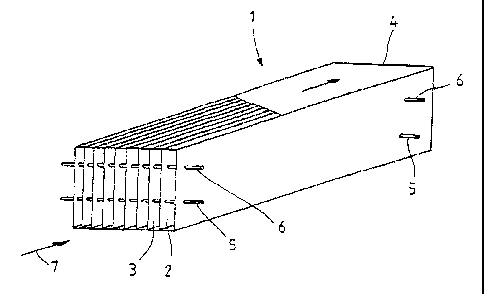
Figure l: a perspective diagrammatic view of one
embodiment of a separator.
Figure 1 is a diagrammatic view of a plate packet that
comprises a plurality of parallel plates, with
unobstructed channels left between them. The intervening
spaces are adjustable, to which end adjusting bolts and
washers can be used. These attachment areas can lie
outside the areas through which the gas flows or, in
contrast to this, they can be covered so as to facilitate
the flow of gas.
The plates 2, 3 can been manufactured from materials that
generate different charges when hot gas flows between
them, so that an electrical field can be built up. This
can greatly facilitate the removal of droplets of liquid,
as described above. The separator 1 incorporates the
9
CA 02204012 1997-04-29
WO 97/00116 PCT/EP96/02651
plates 2, 3 that are arranged within a housing 4 by means
of adjusting bolts 5, 6 in such a way at they can be
adjusted to form suitably narrow channels. In the
embodiment that is shown, the direction of the flow is
indicated by the arrow 7.
The plates can be suspended in cross sections of the
flow, inserted into grooves, or otherwise secured. The
plates can be used as conducting-insulating plates as
emitters or can be used with reversed polarity.
CA 02204012 1997-04-29
WO 97/00116 PCT/EP96/02651
Reference-Numbers
1 - separator
2 - plates
3 - plate
4 - housing
- adjusting bolt
6-- adjusting bolt
7 - direction of gas flow
11