Note: Descriptions are shown in the official language in which they were submitted.
CA 02204065 1997-04-30
-I-
METHOD AND APPARATUS FOR TURN COORDINATION
GAIN AS A FUNCTION OF FLAP POSITION
Field of the Invention
The present invention pertains to aircraft turn control systems, and more
particularly, to a novel system that varies the turn coordination gain of the
aircraft
yaw damper as a function of aircraft flap position.
Backsround of the Invention
In maneuvering an aircraft of fixed-wing configuration, a turn is coordinated
through the operation of multiple control elements. For example, a pilot will
use the
cockpit controls on a fixed-wing aircraft to manipulate the ailerons, rudder
and
elevator of the aircraft to execute the tum.
The employment of computer controlled rudder deflection for turn
coordination during aircraft banking maneuvers has long been practiced. The
coordination of the tum is known to be desirable since, for example, when an
aircraft
is banked left, the aircraft tends to yaw to the right, due to an aileron-
induced moment
about the yaw axis. The yaw axis moment induced during a left bank is
counteracted
by the application of left rudder for a coordinated turn. In modem large
commercial
passenger aircraft, the deflection of the rudder is computer controlled by
means of a
system known as the yaw da:r=per. : hus, a pilot need only manipulate the
wheel in
order to properly execute a turn.
The yaw damper includes various sensors on the aircraft and yaw damper
servos that operate the rudder in response to signals from the yaw damper. Yaw
dampers must determine the amount of rudder deflection for a given amount of
bank
angle as commanded by the pilot of the aircraft. For example, U.S. Patent
CA 02204065 1997-04-30
-Z-
No. 5,452,865 to Tran and U.S. Patent No. 5,072,893 to Chakravarty et al.,
contain
detailed discussions of prior art tum coordination systems.
One crucial portion of the yaw damper is what is known as the gain schedule.
The gain schedule operates to provide turn coordination for the rudder during
a turn
maneuver. Known turn coordination gain schedules are based upon the parameter
Q~,
also known as impact pressure. Specifically, the gain schedule for a Boeing
747-400
is shown in FIGURE I. As seen, the turn coordination gain is constant until a
critical
air pressure, at which point the tum coordination gain decreases in a linear
fashion. It
has been found that the gain schedule shown in FIGURE I does not optimally
provide
for turn coordination, sometimes resulting in a divergent or convergent turn
characteristic.
Summary of the Invention
The present invention provides an improved method and apparatus for
determining the amount of turn coordination gain in an aircraft yaw damper
system
during a turn maneuver. The yaw damper includes inputs from the inertial
reference
units) of the aircraft and also from the flap slat electronic unit (FSEU) of
the aircraft.
The inertial reference units provide information on the aircraft's roll rate,
lateral
acceleration, roll angle, and yaw rate. The FSEU provides to the yaw damper a
signal
indicative of the position of the flaps of the aircraft. The yaw damper
includes a turn
coordination gain box that receives the flap position signal and outputs a
turn
coordination gain value, dependent upon the flap position. The turn
coordination gain
value is then used by the yaw damper to determine the amount of rudder
displacement. Generally, the turn coordination gain value increases as the
flap
position is more extended, indicative of a high lift conftguration of the wing
such as
would be used at low speed. The precise tum coordination gain value for each
flap
position is dependent upon the particular aerodynamic characteristics of the
aircraft
under varying flight conditions.
Brief Description of the Drawings
The foregoing aspects and many of the attendant advantages of this invention
will become more readily appreciated as the same becomes better understood by
reference io the foliowing detailed description, when taken in conjunction
witty the
accompanying drawings, wherein:
FIGURE 1 is an illustration of a prior art turn coordination gain schedule;
FIGURE 2 is a schematic illustration of a prior art yaw damper including a
turn coordination gain section;
CA 02204065 1997-04-30
-3-
FIGURE 3 is a schematic diagram of a yaw damper system in accordance with
the present invention;
FIGURE 4 is a look-up table used in the tum coordination gain box of the
presentinvention;
FIGURES 5-9 are graphical representations of the mathematical models used
to formulate the gain schedule used in the present invention; and
FIGURE 10 is a graph of the turn coordination gain values calculated in
accordance with the presentinvention.
Detailed Desc~tion of the Preferred Embodiment
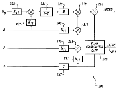
FIGURE 2 shows a simplified prior art yaw damper 201 for generating a yaw
damper command, YDCMD, that controls deflection of the rudder during a turn.
The
YDCMD signal is typically provided to one or more yaw damper servos that
actuate
the rudder of an aircraft- This particular yaw damper 201 is utilized in the
Boeing
747-400 aircraft. The yaw damper 201 uses data input from inertial reference
units
IS located on the aircraft to compute rudder commands (YDCMD) appropriate to
existing flight conditions. The yaw damper servos then translate the
electrical
commands from the yaw damper 201 to control hydraulic flow to an actuator
piston
that moves the rudder of the aircraft-
Input to the yaw damper 201 includes: Ny representing the lateral acceleration
of the aircraft; R representing the yaw rate of the aircraft; ~ representing
the roll
angle of the aircraft; and P representing the roll rate of the aircraft. Each
of these
parameters are provided through the inertial reference units located on the
aircraft.
As can be seen in FIGURE 2, the lateral acceleration Ny is multiplied by a
constant Kl t at a first multiplier box 203. The output of first multiplier
box 203 is
ZS then provided to a first summer 205 which sums the signal output from first
multiplier
box 203 and the output from a second multiplier box 207. The second multiplier
box 207 receives as input the yaw rate R and multiplies the yaw rate R by a
predetermined constant, Klz. The yaw rate R is also provided to a third
multiplier
box 209 that multiplies the yaw rate R by a predetermined constant N12-
The roll angle ~ is provided to a seventh multiplier box 227 which multiplies
the roll angle ~ by a constant, C. The output of the seventh multiplier box
227 is
provided to a fourth multiplier box 211 that multiplies the output of seventh
multiplier
box 227 by a constant Ntg. The output of fourth multiplier box 211 is provided
to a
second summer 213 which adds the output of fourth multiplier box 211 with the
3 5 output of a fifth multiplier box 215. Fifth multiplier box 215 multiplies
the roll rate P
by a predetermined constant Nlq. The output of second summer 213 is provided
to a
CA 02204065 1997-04-30
-4-
third summer-217 which also receives as an input the output of third
multiplier
box 209. The output of third summer 217 is provided to a fourth summer 219.
The output of ftrst summer 205 is provided to a first order lag box 221. The
output of the first order lag box 221 is provided to a sixth multiplier box
223, which
multiplies the output of first order lag 221 by a gain factor M. The output of
sixth
multiplier box 223 is also provided to fourth summer 219. The output of fourth
summer 219 is then provided to a fifth summer 225.
The output of seventh multiplier box 227 is also provided to a turn
coordination gain box 229. The turn coordination gain box 229 also receives as
input
a signal 23 I from the air data computer of the aircraft a signal, such as
airspeed VT"s
(in the case of the Boeing 767) or exterior air pressure Qc (in the case of
the Boeing
747). In the prior art, the input from the air data computer is used to
calculate a turn
coordination gain value that is used to multiply with the output of seventh
multiplier 227. The calculation of the turn coordination gain in the Boeing
747 is in
accordance with FIGURE 1.
In the preferred embodiment of the present invention, the input 231 provided
to the turn coordination gain box 229 is a signal from the flap slat
electronic unit
(FSEU) which indicates the position of the aircraft flaps. Instead of the
prior art,
where the input 231 is either VTpg or Q~, the input 231 in the preferred
embodiment
is flap position. The flaps are located on the wings of an aircraft and are
extended or
retracted to control the amount of lift generated by the wings. The position
of a flap
is typically referred to in degrees. For many aircraft, the flaps can be
placed in one of
several discrete degree positions. Por example, in the Boeing 777, the flaps
may be
placed at 1, 5, 10, 15, 20, 25, or 30 degrees extension from the retracted
position.
Turning to FIGURE 3, the yaw damper system 301 of the present invention
includes a yaw damper unit 303, a yaw damper servo 305, a rudder 307, an
inertial
reference unit 309, and a FSEU 311. Aircraft motion information is provided by
the
inertial reference unit 309 to the yaw damper unit 303. Flap position
information is
provided to the yaw damper 303 by the PSEU 311. The yaw damper unit 303
receives this information and, in accordance with its calculation techniques,
formulates a YDCMD signal to the yaw damper servo 305. In turn, the yaw damper
servo actuates the rudder to the desired deflection. Thus, unlike the prior
art which
relied upon VT,,s or Qc of the aircraft, the present invention relies on the
flap position
of the aircraft to determine the turn coordination gain.
The turn coordination gain box 229 consists of a multiplier and a look up
table
implemented in a microprocessor. The input from seventh multiplier 227 is
multiplied
CA 02204065 1997-04-30
-5-
by the appropriate tum coordination gain value from the look up table. The
look up
table may be implemented in ROM. Based on the flap position as reported by the
FSEU 311, the appropriate tum coordination gain value is used as the
multiplier. A
tabular representation of the look up table is shown in FIGURE 4, with Gl
through
Gg being the possible values of gain.
FIGURES 5-9 illustrate graphically how the tum coordination gains are
calculated and the theoretical basis for the calculations. As is known in the
art,
optimal tum coordination gain requires a neutrally stable spiral mode after
closing the
yaw damper loop. Thus, the gain of the yaw damper must drive the spiral mode
of
the closed loop system to the origin. The gain driving the spiral mode to the
origin
can be obtained by solving the state equations for the closed loop aircraft.
system at a
steady state turn angle. This process can be derived mathematically as
follows:
Let
icl = alxl +blul
YI = clxl +dlul
be the dynamical equation of the airplane model
all a12 a13 ai4
where a21 a22 a23 a24 _ R ~ p - sideslip
al = xl angle
=
a31 a32 a33 a34
a41 a42 a43 a44
b l l NY
b1z R
b13
bl= ; ul=~8r~ ; YI=
bl4
cll c12 c13 c14 ~ dll
X21 X22 X23 X24 d2l
C1 _
- ~
dl
X31 X32 e33 X34 d31
~4l X42 X43 X44 d41
The block diagram representation of the equations above is shown in
FIGURE 5.
CA 02204065 2004-10-18
-s-
The matrices a1, b1, c1, d1 represent the aerodynamic model for the particular
aircraft that is being modeled. The parameter a 1 represents the amount of
rudder
deflection. It can be appreciated by those skilled in the art that these
matrices can be
calculated in accordance with known techniques based upon the physical
dimensions
g of the aircraft and the flight parameters of the aircraft. Moreover, the
matrices a1, b1,
c1, d1 will be different for different flap positions of the aircraft: This is
because when
the flap positions of the aircraft change, the aerodynamic characteristics of
the aircraft
change, thereby changing the matrices that define the behavior of the
aircraft.
Next, let
ic2 - a2x2 + b2u2
Y2 = c2x2 + d2u2
be the dynamical equation of the yaw damper (without the turn coordination
path),
Ny
R
where a2 =~j~ ; b2 =~k11k12ki3k14~ ~ u2 =
P
Y2 =~ Ydcmd~ ; c2 =~m~ ; d2 =[n1~ n12 n13 nial
Its block diagram representation is shown in FIGURE s.
The values of a2, b2, y2, c2, and d2 may be obtained from the yaw damper
system of the particular aircraft. Thus, the values of b2, c2, and d2 can be
obtained
from the multipliers shown in FIGURE 2. Connecting the output of the airplane
(y1)
to the input of the yaw damper (u2) in series, the resulting block diagram
representation of the system is shown in FIGURE 7,
ZS where a. = a _0 , b, _ b1 ;'c' = d2clc2
b2c1 a2 ~ ~b2dl~~d'- d2d1
Since n11~ d21' d31' & d41 ~e always equal to zero, then d' = d2dl = 0.
Closing the
loop by connecting the ydcmd (y2) to the Ar, (u1), the block diagram
representation
of the closed Poop system is shown in FIGURE 8. Ar is the amount of rudder
needed
t~'ough role angle feedback to keep the airplane from being divergent or
convergent.
This closed loop system can be simplified as shown in FIGURE 9,
CA 02204065 1997-04-30
bii
bit where
where A=a'+b'c' ; b'= bi3
bi5 = bzdl
614
61s
The state equations of the closed loop system can be expanded as follows:
p=Alit+AI2R+Ai3$+AIqP+A15X+bilbr
R=A21P+AzzR+A234~+A2qP+AzSX+b128r
d'=A31~+A32R+A33$+A3qP+A35X+6138r W (1)
P = Aq1 (3 + Aq2 R + Aq3 ~ + Aqq P + Aq5 X + b 1q 8r
X=A51~+A52R+A53$+ASqP+A55X+6158r
where A=a'~~+b';tc'1~
For a steady state turn
~=constant==)) P = 0 & P =0;
R=constant==))lt=0&X=0;
(3 =constant==)) (3 =0;
Thus, Eq. (1) becomes
~ =Att p+ At2 R+A13 ~+A1q P+A15 X+bli Sr =0
R=A21~3+A22 R+A23~+A2qP+A25X+bitcSr =0
~=A3la+A3zR+A33~+A3qP+A35X+613br=0 Eq~(2)
P =Aq1(3+Aq2 R+Aq3~+AqqP+AqSX+biqbr =0
X=A51~+A52 R+A53$+A5q P+A55X+b158r=0
Eq: (2) can then be solved for Ar at a constant value of roll angle. Ar is the
amount
of rudder needed through roll angle feedback to keep the airplane from being
divergent or convergent. Once the value of Ar has been calculated, tloe ideal
tum
coordination gain value can be calculated simply as the Ar divided by a
constant for
that aircraft.
CA 02204065 1997-04-30
_g_
The values for the matrices at, bt, ct and dt will vary depending upon the
operational flight conditions of the aircraft, including flap position. For
example,
aircraft variations in speed, weight, altitude, flap position and center of
gravity will
have an influence on the matrices. In the preferred embodiment, matrices are
used
that include extreme values of these operational parameters. The resulting
turn
coordination gain used in the look up table is then calculated as the mean of
the rum
coordination gains calculated using the various extreme matrices. This ensures
that
the rum coordination gain box 229 has taken into account all possible flight
conditions.
For example, turning next to FIGLJItE 10, actual turn coordination gain values
were calculated for the Boeing 747-400 aircraft for various flap positions,
namely,
one, five, ten, and twenty degrees. Note that there are several rum
coordination gain
values for each flap position. This corresponds to the various extreme
operating
conditions of the aircraft. In the preferred embodiment, the turn coordination
gain
used in the look-up table will be the average of the extreme values.
While the preferred embodiment of the invention has been illustrated and
described, it will be appreciated that various changes can be made therein
without
departing from the spirit and scope of the invention.