Note: Descriptions are shown in the official language in which they were submitted.
- . -
CA 02204138 1997-04-30
METHOD AND SYSTEM FOR MEASURING
AND ~nJUSTING PRESS~RE OF TYRE
OBJECT OF T~E INVENTION
The present invention relates, as its title indicates, to
a method which allows to measure tyre pressure and adjust it to
reference values, taking into account the variations which may
have beeen produced in said reference values due to changes in
tyre temperature.
BACKGROUND OF THE INVENTION
One of the factors which directly affects the driving of
a vehicle is the pressure of the tyres and, although checking
the pressure should be, in principle a simple operation, when
the user attempts to carry out the checking he finds a series
of problems that in many occasions lead him to give up the
attempt as such operation implies loss of time while i~ also
gives rise to getting the users hands dirty, or at best, the
user inflates tyres untill a value of pressure which he
believes to be the correct one, while the appropriate pressure
at that particular moment would be different.
The problem for the user when checking the pressure is
that he has to obtain the pressure values corresponding to
front and rear wheels; however these values vary depending upon
whether the tyres are cold or warm. As the quantification of
these factors is subjective, the user usually chooses an
average pressure or a reference pressure value that he
considers the most suitable.
At present there are known pressured-air supplying
machines on the market, which incorporate a series of push-
buttons, each one of which corresponding to a pre-determined
pressure value, so that when one of the push-buttons is pressed
the machine adjusts the tyre pressure to the value assigned to
the pressed push-button.
CA 02204138 1997-04-30
The influence of temperature of the tyres on their
pressure is important; that is why tyre manufacturers recommend
an increase of the reference value of 0.3 bar if the pressure
is checked when tyres are warm. In doing so, the problem of
determination of the temperature of the tyre comes across, as
this temperature may vary more than 50~C depending upon the
environmental temperature and, on the other hand, upon whether
the tyre has been resting or it has just finished running at a
high speed.
DESCRIPTION OF THE INVENTION
In order to overcome these problems, the system which is
object of this invention has been developed, which allows to
determine the pressure equivalent to the nominal pressure given
by the tyre manufacturer, as a function of the temperature of
the tyre at the moment of carrying out the reading and to
supply said equivalent pressure by means of a pressured-air
machine, which forms part of the system. The equivalent
pressure is therefore a pressure which under temperature
conditions different from the environmental temperature would
be the appropriate one for the use of the tyre.
The method of the invention therefore permits, during the
pressure checking and during the adjustment of the same, to
know which is the present pressure of the tyre, the temperature
inside the same and the corresponding pressure that it should
have, as a function of the temperature inside the tyre as well
as the nominal pressure at environmental temperature given by
the manufacturer.
Once the temperature and the present pressure of tyre are
known, the user can effect the pressure adjustment either
manually, or by using an automatic adjustment procedure.
In order to know the data corresponding to the present
temperature and pressure of a tyre, the system of the invention
uses a sensor mechanism installed inside the tyre.
CA 02204138 1997-04-30
According to an embodiment of the invention, the system
consists of a valve which may be the conventional inflating
valve which incorporates a thermocouple, a portable pressure
tester and a pressured-air supplying machine.
The valve incorporates a thermocouple which emerges out
from the back zone of the valve, thereby permitting the
thermocouple remain located inside the tyre when the valve is
mounted thereon, the conductors of the thermocouple having at
the ends thereof a pair of contact points outside the valve at
the front zone of the same.
The portable pressure tester, of digital type, has a
mouthpiece for connection with the valve, and contact points
which may be connected to the contact points of the valve
thermocouple, the tester being capable of reading the pressure
of the tyre and the temperature inside the same simultaneously.
The tester has several push-buttons by means of which the
nominal pressure value of the tyre at ambient temperature,
which is a value given by the manufacturer, is is introduced
therein; and a display on which nominal pressure values,
temperature detected by the thermocouple, present pressure of
the tyre and the correct pressure of the tyre are visualized.
The later is calculated from the data corresponding to the
nominal pressure at environmental temperature and the detected
temperature, by means of a microprocessor included in the
tester.
In order to obtain the formula which would permit the
calculation of the pressure corresponding to a nomial pressure
in terms of temperature, the following premises are assumed:
1. Tyre volume variation is negligible in spite of pressure
changes, as the pressure variation affects the rigidity of the
tyre and the inside canvas frame avoids a substantial change of
volume.
2. Pressure variation due to temperature is linear, as there
are no changes in gas physical state.
CA 02204138 1997-04-30
The above point is based on Gay-Lussac's Law of the
Behaviour of Gases, that is governed by the following formula:
P-V = n-R-T
Wherein P, V and T are variables of pressure, volume and
temperature respectively , n is the number of moles and R is
the gas constant of perfect gases. In case of constant volumes
, the following proportion can be derived from the above
formula:
PA/T~ = P. /Tl
Wherein PA is the nominal pressure recommended by the
manufacturer at enviromental temperature (293 K, equal to
20~C)
Therefore, the formula that permits the calculation cf the
equivalent pressure in terms of temperature is the following:
P1 = (T + 273)-Po/293
Wherein Pi is the corrected equivalent pressure in terms
of temperature, T is temperature (in ~C) measured inside the
tyre by the thermocouple, and P0 is the pressure at ambient
temperature (293 K) recommended by the vehicle manufacturer.
The system of this invention further comprises an air
supplying machine to adjust tyre pressure, taking into
consideration the temperature inside the same. This machine has
a connection mouth for connection with the tyre valve, provided
with contact means suitable for making contact with the
contact points of the thermocouple when the connection mouth is
connected to the valve, the machine thus peforming simultaneous
reading of values correponding to the present pressure of tyre
and the present temperature inside the same.
In the same manner as that of the pressure tester, the air
supplying machine has a keyboard, by means of which the nominal
pressure value is introduced; a microprocessor adapted to
calculate an equivalent pressure, using data from the nominal
pressure and the temperature inside the tyre; and a display on
CA 02204138 1997-04-30
which data regarding nominal pressure, present pressure,
temperature and equivalent pressure are visualized.
Said connection mouth ~or connection with the valve
further has means to effect a safe blocking on the valve when
said connection mouth is fixed on the same.
The arrangement of the blocking means is such as to permit
the mouth to remain firmly attached to the valve during the
operation of pressure adjustment, whereas when the operation is
enaed, it can be easily unblocked by the user by pulling from
0 an external case of the same. This disposition is made possible
due to the use of a generally cylindrical body with
longitudinal grooves which allow said body to be subject to
perimeteral compression, thus reducing its diameter, thereby
making possible a firm grip of the same over a valve.
Furthermore, said air supplying machine optionally
incorporates an auxiliary tool which permits to screw or to
unscrew the core of the valve if deemed necessary.
Said tool consists of an essentially cylindrical body
which has a cavity at one end, axially disposed to allow the
placing of a rod shaped element therein whose free end has a
configuration suitable for being coupled to a core. Said tool
further has, at the opposite end thereof, another cavity
axially arranged, which has a wrench-like configuration which
permits the manipulation of valves, end caps or any element
related to this field.
The tyre pressure adjustment is carried out by a pneumatic
equipment included within the machine, said equipment being
activated either by a control circuit governed by the
microprocessor if the user chooses the equivalent pressure
calculated by the machine; or manually by means of using push-
buttons (+) and (-), in case that the user prefers to put a
pressure different to the calculated one.
According to another embodiment of the invention, the
process of checking the present temperature and pressure of the
CA 02204138 1997-04-30
tyre is carried out by means of a sensor and emitter device
attached to the surface of the rim of the tyre which remains
inside the tyre, so that in operation conditions, it can
directly detect said present pressure and temperature of the
tyre.
Thw data obtaines are subsequently converted into
electronic signals which are then converted into radiofrequency
waves and are transmitted towards the outside of the tyre.
Said radiofrequency waves are later received by a portable
receiver set arranged as a remote control apparatus which also
serves for switching said receiver and emitter device on.
Said remote control apparatus further has several push-
buttons by means of which the nominal pressure value of the
tyre at ambient temperature, which is a value given ky the
manufacturer, is manually introduced therein; and a display
means for displaying values of the nominal pressure, the
present temperature and pressure both detected by the sensor
device, as well as the equivalent pressure of the tyre which is
calculated by a microprocessor included in the remote control
apparatus in the same manner as described hereinbefore in the
case of the pressure portable tester.
Once the equivalent pressure which is required for the
tyre at the moment of checking is known, the user introduces
this data into an air supplying machine with characteristics
as mentioned above , in order to adjust the tyre pressure.
It is to be pointed out that in this embodiment, the air
supplying mouth would not need the use of contact means to
perform the proper reading of the present temperature and
pressure inside the tyre.
The receiver and emitter device essentially consists of at
least one thermocouple, a pressure detector, a circuit for
reception and emission radiofrequency waves, a circuit for
converting radiofrequency waves into electronic signals and
CA 02204138 1997-04-30
vice versa and a power supply circuit which operates by using
electronic energy supplying batteries.
Advantageously the air supplying machine incorporates
means for receiving radiofrequency signals emitted from said
remote control apparatus in order to detect said signals and
process them to obtain data related to the equivalent pressure
which has to be supplied to the tyre by the air supplying
machine itself.
For that purpose, said machine may incorporate a
radiofrequency waves receiver and a converter for converting
radiofrequency waves into electronic signals which are later
supplied to the microprocessor incorporated in the air
supplying machine.
In this manner, the user will initially use the remote
control apparatus to detect the present temperature and
pressure of the tyre, calculate the equivalent pressure to be
given to the tyre, and transmit the value thereof to the air
supplying machine, which after receiving said value, starts
the operation of adjusting the tyre pressure in accordance with
the equivalent pressure.
Optionally, the remote control apparatus may be
incorporated in the front panel inside the vehicle where the
user can control and check the pressure and the temperature of
the tyre without having to get out of the vehicle, or even
perform the controlling and checking during the driving.
In this latter case, the remote control apparatus will
effect the measurement of present pressure and temperature of
each tyre of vehicle separately and it will visualize them
successively, or by according to the selection choice of the
user.
For this purpose, the microprocessor of the remote control
apparatus must be programmed to effect independant readings of
each one of the wheels.
CA 02204138 1997-04-30
The method and system for vehicle tyre pressure measuring
and adjusting described above further allows the automatic
execution of certain functions, without a direct intervention
of the user.
One of said functions, described herein in a non-
limitative manner, is to perform the pressure measurement and
adji~stment of each tyre of the vehicle using a valve locating
mechanism and a subsequent connection of the air supplying
mouth-pieces to each valve.
In order to carry out this operation, the wheels Gf the
vehicle are located on rollers operated by means of a motor or
a similar mechanism so that their synchronized rotation makes
the vehicle wheel rotate untill its valve is placed at a pre-
determined position where it will receive an air supplying
mouth-piece which carries out the measurement and the further
ad,ustment of tyre pressure.
To place tyre valve in said pre-determined position use is
made of a proximity detection process.
DESCRIPTION OF THE DRAWINGS
To complete the description provided and in order to
achieve a better understanding of the features of the invention
the present description is accompanied by a series of drawings,
as an integral part of the same, representing in an
illustrative and non-limitative manner the following:
-Figure 1 shows a front view of the valve which forms a
part of the system for measurement and adjustment of tyre
pressure, mounted on a tyre, wherein the peripheral material of
the same has been longitudinally cross-sectioned to allow the
observation of the thermocouple.
CA 02204138 1997-04-30
-Figure 2 shows a front view of the pressure tester,
wherein the connection mouth of the same has been partially
cross-sectioned.
-Figure 3 represents a partially cross-sectioned front
view of the connection mouth of the pressured-air supplying
machine.
-Figure 4 shows a front view of the air supplying machine.
-Figure 5 shows a block diagram of the air supplying
machine.
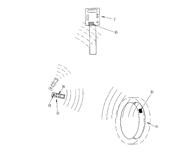
-Figure 6 shows a diagram of the setting of a sensor and
emitter device on a wheel rim as well as the remote control
apparatus in relation to the tyre and the air supplying
machine.
-Figure 7 is a block diagram of the main components of a
sensor and emitter device.
-Figure 8 is a block diagram of a remote control
apparatus.
-Figure 9 is a front view of an air supplying mouth with
blocking means axially cross-sectioned according to a vertical
plane.
-Figure 9(a) is a perspective view of a blocking body of
the mouth of Figure 9.
-Figure 10 is a front view of an auxiliary tool employed
to screw and to unscrew the valve core of a valve, axially
cross-sectioned according to a vertical plane .
-Figure 11 is a diagram of an automatic pressure
measurement and adjustment system using rotatable rollers.
CA 02204138 1997-04-30
PREFERRED EMBODIMENT OF THE INVENTION
As it may be observed from the referenced figures, the
tyre pressure measuring and adjusting system consists of a
valve (1), a pressure tester (2) and an air supplying machine
(3).
The valve (1) incorporates a thermocouple (4) which juts
out the rear zone of the same such that the thermocouple (4)
remains located inside the tyre (5); one of the conductors (6)
of the thermocouple is connected to a cylindrical-shape metal
body (7) of the valve (1) whereas the other conductor (8~ is
connected to a peripheral ring (9) embeded ir.side the
insulating material which evolves the metallic body (7),
thereby, both contact means (7) and (9) remain separated and
electronically isolated.
The pressure tester (2) has a tip (10), which can be
coupled to the valve (1) to read the inner pressure of the tyre
(5); this tip has an extension made of insulating materia~ (11)
and a central conductive part (12).
A contact (13), sized to touch the contact (9) of the
thermocouple when the tester (2) is coupled to the valve (1),
emerges from the isolating part (11); when performing this
coupling to determine tyre pressure, the metallic body (7) of
the valve and the central part of the tester (12) also make
contact with each other, that is why it carries out the reading
of the present pressure and the temperature inside the tyre (5)
simultaneously.
The present pressure and temperature values are registered
by a microprocessor inside the tester (2).
The tester has several push-buttons (14) externally which
have pre-determined values assigned thereto, corresponding to
the pressure values most commonly used. sy switching on the
corresponding push-button (14) the nominal pressure value, at
CA 02204138 1997-04-30
environmental temperature, given by the vehicle manufacturer,
is introduced in the microprocessor.
The tester (2) further has two other push-buttons (15)
which allow to increase or reduce the nominal pressure value as
provided by means of any of the push-buttons (14), these being
employed to introduce the nominal pressure value in the
microprocessor in the case where said value would not coincide
with anyone of the those assigned to the push-buttons (14).
When the microprocessor of the tester (2) already h~s the
nominal pressure values of the tyre, the temperature inside the
same and its present pressure, it calculates the pressure
equivalent to the nominal one bearing in mind the temperature
variation and it visualizes all data on the display (16) of the
tester, so that user can check if the present pressure
corresponds to the calculated equivalent pressure.
The machine (3), in charge of adjusting tyre pressure
incorporates a hose (17) which ends at a mouthpiece (18),
suitable to be coupled onto the valve (1).
The mouthpiece (18) defines an external isolating part
(19), from which a contact means (20) emerges, and an inner
part (21) made of conductive material which forms another
contact means; such that when the mouthpiece (18) of the
machine (3) is coupled onto the valve (1), contact means (20)
and (21) of the mouthpiece (18) are connected to those (7) and
(9) of the thermocouple, the machine (3) simultaneously
performing the registration of the temperature and pressure in
a microprocessor located inside the same.
According to an embodiment of the mouthpiece, represented
in Figure 9, the mouthpiece (40) consists of a evolving body
(41) which has a cylindric portion with a larger diameter over
the surface of which there are several ribs presented to
facilitate the handling of the mouthpiece and another
cylindrical portion with a smaller diameter which forms
together with the first portion the evolving body inside which
the mouthpiece components are located. Said components include
CA 02204l38 l997-04-30
an outlet tip (42) which is threaded at an end inside a
blocking body (43). This blocking body (43) has a generally
cylindrical configuration which, in one end where said outlet
tip (42) iS threaded, has a longer diameter and along the
remaining surface has several longitudinal grooves (44) as can
be seen in Figure 9(a). Said grooves allow the mobility of
movable portions (45) adjacent to the same as the blocking body
(43) iS made of a preferably metallic material with certain
flexibility in a radial direction.
The blocking body (43) has mobility in an axial direction
inside the evolving body (41) whereas movable portions (45)
remain located in the same. Said evolving body (41) has at its
end opposite to the outlet tip (42) and on its inner surface,
a perimetric recess (46). Additionally, the blocking body (43)
has in the free ends of each one of the mobile portions (45) a
salient portion ( 47).
With this arrangement the blocking body (43) has mobility
inside the evolving body (41) untill the point of coincidence
of salients (47) with the perimetric recess (46). At this point
salients (47) fit into perimetric recess (46) due to the effect
of mobile portions (45) which tend to open outwards in a radial
direction thereby obtaining a larger diameter in the opening
part (48). Therefore, when the end of a tyre valve is
introduced into the opening (48) of the blocking body (43) when
the latter is in a situation of the opening (48) having its
larger diameter, the evolving body (41) slides over the
blocking body (43) in a direction opposite to the entry of the
valve, for example in the direction of arrow "F" in Figure 9.
Said movement makes the salient portions (47) of the blocking
body (43) to move out of the perimeteral recess (46) thereby
reducing the diameter of the opening (48) which has the end of
the tyre valve inside.
Said diameter reduction of opening (48) on the valve
produces the blocking effect of the blocking body (43) on the
valve.
CA 02204l38 l997-04-30
In order to unblock the valve, the evolving body (41)
slides in a direction opposite to arrow "F" untill salient
portions (47) again fit into the perimeteral recess (46),
thereby increasing the diameter of opening (48) which allows
the valve of the same to be moved out.
The mouthpiece (40) further consists of a series of pieces
which allow its functionality such as a cylindrical sleeve (49)
which at a first end thereof is attached to the outlet tip (42)
and at another end has a base surface (50) with a central
orifice through which rod (51) passes. This latter, at the end
corresponding to the entry of the tyre valve, has a plane base
which rests over the valve core, and at the opposite end it has
a cubic or rectangular-prismatic configuration which permi~s
the passage of air and which rsts on an end of a spring (52)
whose effect is that rod (51) exerts pressure on valve core. On
the base surface (50) of the sleeve (49) an elastic joint (53),
made of rubber for example, is arranged whose objective is to
provide sealing when the valve is introduced into the opening
(48) and lays on the joint (53). Additionally the cervoclip
(54) arranged in the opening corresponding to outlet tip (42)
tends to avoid the inside mechanism of the evolving body (41)
from moving out.
The air supplying machine (3) optionally has an additional
tool which permits the threading and unthreading the core of
tyre valves.
Said tool (60), as shown in Figure 10 consists of an
essentially cylindric body (61) which has at an end a cavity
(62) axially disposed to permit the lodging of a rod shaped
utensil (63), whose free end (64) has a suitable configuration
to couple on a core. Said rod (63) remains fixed inside the
cylindric body (61).
At its opposite end, tool (60) has another cavity (65)
axially disposed which has a first portion (66) with a larger
diameter and a keyshaped configuration which permits operation
on valves, end caps or any element related to the field of
CA 02204l38 l997-04-30
14
tyres. Said cavity (65) also consists of a second portion (67)
intended to allow the introduction of the ends of valves while
they are being manipulated by means of the first keyshaped
portion (66).
The machine (3), in the same manner as that of the tester,
externally has push-buttons (22) which have specific values
assigned thereto corresponding to the pressure values mostly
used. Each one of said push-buttons (22) may preferably have a
colour specially assigned to its pressure value. By activating
10 the corresponding push-button (22), the nominal pressure value
of tyre at enviromental temperature as given by the vehicle
manufacturer, is introduced into the microprocessor, the
microprocessor making the calculation of the pressure
equivalent to the nominal depending on temperature. The machine
15 (3) further incorporates two push-buttons (23) which permit to
adjust the nominal pressure value in the case where it would
not coincide with any push-button (22).
The microprocessor of the machine is connected to a
display (24), on which data regarding nominal pressure, present
20 pressure, equivalent pressure and temperature are displayed;
and to a control circuit (25) which controls a pneumatic
equipment (26) in charge of adjusting the tyre pressure by
introducing or extracting air in and out of the same
respectively, by means of the hose (17).
In this manner, if push-button (22) corresponding to a
pre-determined nominal pressure is activated and the mouthpiece
(18) is connected to the valve (1), the microprocessor
calculates the equivalent pressure and acts on the pneumatic
equipment (26) by means of control circuit (25), adjusting the
30 tyre pressure to the calculated equivalent pressure value.
If the nominal pressure does not coincide with any of the
values assigned to the push-buttons (22), the value is manually
adjusted by push-buttons (23), the machine then providing the
selected pressure, as if it were a conventional machine.
CA 02204138 1997-04-30
If any pressure is manually selected by actuating push-
buttons (23) and later it is desired that the machine provide
the pressure equivalent to the same as a function of
temperature, it will be sufficient to press the push-button
(27), which makes the microprocessor calculate the equivalent
pressure and to order the pneumatic equipment to supply said
pressure.
Referring to figures 6, 7 and 8 an alternative embodiment
of the object of the invention is described, according to which
a sensor and emitter device (30~ is attached to the surface of
a tyre rim (31~ so that when said rim carries the corresponding
pneumatic tyre (shown in broken lines), said device (30)
rem~in.s inside the tyre to effect the detection of the present
pressure and temperature of tyre.
Said device, as it can be seen in figure 7, consists of a
microprocessor which governs the operation of the same, a
radiofrequency wave receiver and emitter, a converter of
radiofrequency waves into electronic signals and vice versa, a
pressure meter and a thermocouple.
The remote control apparatus (32) consists of a
microprocessor, a display device (DISPLAY), a radiofrequency
wave receiver and emitter, a converter of radiofrequency waves
into electronic signals and vice versa, a supply device,
normally a battery, a keyboard (33) and several push-buttons
(34) to increase and decrease values shown in the display.
With this arrangement and in order to carry out the
measurement of the present pressure and temperature of tyre,
the user uses the keyboard (33) to send the correspondig signal
for commanding the sensor and emitter device (30) so that the
latter performs the corresponding readings of pressure and
temperature.
As it has been mentioned hereinabove said command is
carried out through radiofrequency waves which are transmitted
through the transmitter set of the remote control apparatus and
which are received by the receiver of the sensor and emitter
CA 02204138 1997-04-30
device (30). Said radiofrequency waves are later converted into
electronic signals by means of the converter of said device
(30)/ which are sent to the microprocessor of the same. The
latter, having received the corresponding signal, e fects the
measurement of the pressure by the pressure meter, and of the
temperature by the thermocouple of the sensor and emitter
device (30). Once the measurements are carried out, the
microprocessor sends the signals corresponding to measured data
to the converter for their convertion into radiofrequency waves
which are emitted towards the outside by the radiofrequency
emitter of the sensor and emitter device (30).
The waves emitted by said device (30) are received by the
radiofrequency receiver of the remote control apparatus ~32)
and once converted into electronic signals by the converter of
said apparatus, they are sent to the microprocessor of the
same. This latter, according to the received values calculates
the equivalent pressure with which the tyre is to be provided.
All data related to the present pressure and temperature and
nominal pressure can be visualized through the display of the
remote control apparatus (32).
In this manner, the user obtains a pressure value which is
the appropriate one for the tyres under the conditions of
checking . For that reason, it would be sufficient to introduce
the value corresponding to said equivalent pressure in the air
supplying machine and proceed with the adjustment of tyre
pressure.
Advantageously, the air supplying machine (3) incorporates
a radiofrequency waves receiver device (35) capable of
receiving the waves emitted by the remote control apparatus
(32) as it is shown in Figure 6. In this way, once the value of
pressure equivalent to the nominal for tyre has been obtained,
the user directs the remote control apparatus towards the air
supplying machine (3) and by pressing the corresponding push-
button, the user immediately sends by way of radiofrequency
waves the value of the equivalent pressure to the receiver
device (35) of the air supplying machine (3). Said receiver
CA 02204138 1997-04-30
device (35) provides the microprocessor of the air supplying
machine (3) with the value of the equivalent pressure by means
of electronic signals, the microprocessor thus automatically
starting to supply the equivalent pressure to the tyre. The
process for the reception of radiofrequency waves untill their
sending to the microprocessor is similar to that of the sensor
and emitter device (30) and that of the remote control
apparatus (32) for which in order to avoid repetitions its
detailed description is ommited .
~t is to be mentioned that the air supplying machine may
carry out, by means of its microprocessor, the calculation of
the pressure equivalent to the nominal, so that in this case
this task would not be carried out in the remote control
apparatus; the latter therefore would only be limited to the
sending of the values of the present temperature and pressure
of tyre to the air supplyir.g machine.
Optionally the remote control apparatus (32) may be
installed into the vehicle, for example in the front panel of
the inner space of the same, in such a manner that the user,
for example the driver, while driving can effect the checking
of the present pressure and temperature of each tyre of the
vehicle.
The method for measurement and calculation of the
equivalent pressure is similar to that of the previous case
except that in this case the remote control apparatus would
emit and receive radiofrequency waves related to each wheel
through independent activator devices installed nearby each
tyre and intended to activating a sensor and emitter device
(30) of each corresponding wheel.
Said independent activator devices are installed in the
bodywork of the vehicle and are connected by cables to the
remote control apparatus installed inside the vehicle.
In this way the driver or any other occupant of the
vehicle would be able to check data regarding the present
CA 02204l38 l997-04-30
18
pressure and temperature and to calculate the equivalent
pressure of each wheel, even while the vehicle is in movement.
In this case the remote control apparatus displays the
values corresponding to each wheel independently, either
successively or by pushing a key corresponding to a wheel and
further keys corresponding to other wheels.
The method and the system for pressure measurement and
adjus~ment described hereinabove further permi~ the execu~lon
or cer~ain functions in an automatic manner and without the
direct intervention of the user.
One of said functions, here described in a non-limitative
manner, is to effect the pressure measurement and adjustment of
all the tyres of the vehicle automatically.
In order to do so, a mechanism for locating the valve of
the tyre is used. As it is shown in figure 11, said
localization mechanism (70) consists of several rollers (71)
arranged to allow the wheel (72~ to be situated thereon, while
they are capable of rotating around a respective axis (73) by
means of the activation of a motor (79) or a similar system, in
such a way that their synchronized rotation forces the wheel
(72) to rotate around its axis (74).
Due to said rotation of the wheel (72), the tyre valve
(75) moves in a circular path untill a proximity detection
device (76) detects its presence. The detection of the presence
of valve (75) is communicated by electronic signals to a
control equipment (77).
Said equipment uses a microprocessor (not shown in figure)
which governs the automatic operation of the whole system.
After having detected the presence of said valve, said
microprocessor sends a stopping signal to the working mechanism
(79) thereby stopping the rotation of roller (72). Therefore
valve (75) remains situated in a pre-determined position to
later receive the air supplying mouthpiece (80).
CA 02204138 1997-04-30
19
Once the valve is situated in said pre-determined
position, the microprocessor of the control equipment (77)
commands a mechanism (78) for activating the air supplying
mouthpiece (80) to make the latter move and be placed on the
valve (75).
Once the mouthpiece (80) is placed on the valve (75), the
process of pressure measurement and adjustment is carried out
as described above.
This automatic operation system may be installed in places
where vehicles call in order to obtain services such as a car
wash, a vehicle technical inspection station, etc.
It is not considered necessary to ma~e the present
description more extensive in order to let any expert in the
matter to understand the scope of the invention and the
advantages which are derived from the same.
The terms in which this description has been drafted
should always be taken in a wide and non-limitative sense.
Materials, shape, size and disposal of elements are
susceptible to variation as long as it does not imply an
alteration of essential features of the invention, which are
claimed as follows.