Language selection

Search

Patent 2204336 Summary

Third-party information liability

Some of the information on this Web page has been provided by external sources. The Government of Canada is not responsible for the accuracy, reliability or currency of the information supplied by external sources. Users wishing to rely upon this information should consult directly with the source of the information. Content provided by external sources is not subject to official languages, privacy and accessibility requirements.

Claims and Abstract availability

Any discrepancies in the text and image of the Claims and Abstract are due to differing posting times. Text of the Claims and Abstract are posted:

  • At the time the application is open to public inspection;
  • At the time of issue of the patent (grant).
(12) Patent: (11) CA 2204336
(54) English Title: CHRISTMAS LAMP SOCKET
(54) French Title: SUPPORT DE LAMPE DE NOEL
Status: Expired and beyond the Period of Reversal
Bibliographic Data
(51) International Patent Classification (IPC):
  • F21S 4/15 (2016.01)
  • F21V 19/00 (2006.01)
  • H01R 13/52 (2006.01)
  • H01R 33/06 (2006.01)
(72) Inventors :
  • HUANG, SHUN-FENG (Taiwan, Province of China)
(73) Owners :
  • SHUN-FENG HUANG
(71) Applicants :
  • SHUN-FENG HUANG (Taiwan, Province of China)
(74) Agent: ADE & COMPANY
(74) Associate agent:
(45) Issued: 2000-01-25
(22) Filed Date: 1997-05-02
(41) Open to Public Inspection: 1998-11-02
Examination requested: 1997-05-02
Availability of licence: N/A
Dedicated to the Public: N/A
(25) Language of filing: English

Patent Cooperation Treaty (PCT): No

(30) Application Priority Data: None

Abstracts

English Abstract


A Christmas lamp socket includes a housing, a lamp
base with a lamp fitted therein and inserted in the
housing completely. The housing has two aligned grooves
in a bottom end for a power wire to be fitted and
positioned therein with a proper tenseness so as to enable
the sockets kept upright to the wire and thus to prevent
rain from flowing in the housing and the lamp base and
from consequent short circuit.


French Abstract

Un support de lampe de Noël comprend un logement, une base de lampe avec une lampe qui y est posée et qui est introduite complètement dans le logement. Le logement comporte deux rainures alignées dans le fond permettant de poser un fil d'alimentation avec la tension appropriée pour que le support soit maintenu debout au-dessus du fil et qu'ainsi la pluie soit empêchée d'entrer dans le logement et la base de la lampe de manière à prévenir les courts-circuits.

Claims

Note: Claims are shown in the official language in which they were submitted.

WHAT IS CLAIMED IS:
1. A Christmas lamp socket comprising a housing, a
conventional lamp, a lamp base for combining said lamp
thereon and a power wire, and characterized by said
housing having two aligned grooves in a bottom end for
said power wire to be fitted therein with a proper
tenseness in forming a net of Christmas lamps using said
sockets.
2. The Christmas lamp socket as claimed in claim
1, wherein two vertical holes are further provided in
the bottom end of said housing for said power wires to
fit therein, permitting said lamp base sealed in said
housing after inserted in said housing so as to prevent
rain from flowing in said housing and in said lamp base.
-6-

Description

Note: Descriptions are shown in the official language in which they were submitted.


' ~ CA 02204336 1997-0~-02
CHRISTMAS LAMP SOCKET
BACKGROUND OF THB INVENTION
This invention concerns a Christmas lamp socket,
particularly having a two aligned grooves and two holes
in a bottom portion for fitting electric power wires 60
as to save time and cost in assembling.
A known conventional Christmas lamp socket shown
in Figs. 4 and 5 includes a housing 11, a lamp 12, a
lamp base 13 and a power wire 14. The housing 11 has two
opposite vertical tubular hooks 111, 111 for holding
holding power wires 14, 14 in place.
However, the conventional Christmas lamp socket
has drawbacks a6 listed below.
1. The vertical tubular hooks are definite in
length, and it is not easy to insert the power wire
therein. Besides, the tubular hooks may break if force
used in inserting the power wire is too large, in addi-
tion to the time needed in assembling being long to re-
sult in high cost.
2. To form a mold for the housing with the tubu-
lar hooks is rather difficult, resulting in a high cost.
3. If a net of Christmas lamps using the conven-
tional sockets is hung outdoors, rain may flow in the
housing and the lamp base to cause short circuit, which
has latent danger for a possible fire.

' , CA 02204336 1997-05-02
SUMMARY OF TH~ INVENTION
A main purpose of the invention is to offer a
Christmas lamp socket having a housing provided with two
aligned grooves in a bottom portion for positioning a
power wire, simplifying assembling a power wire with the
housing.
Another purpose of the invention is to offer a
Christmas lamp socket provided with two vertical holes
in the bottom portion, ju~t for power wires to fit
therein, so a lamp base may be completely inserted in a
sealed condition so that rain may be prevented from
flowing in the housing and the lamp base, without possi-
bility of happening short circuit by rain.
The main feature of the invention is positioning
grooves provided in a bottom end of the housing for fit-
ting a power wire therein with a proper tenseness and
two vertical holes also in the bottom end of the housing
for just inserting respectively a power wire.
BRIEF DESCRIPTION OF DRAWINGS
This invention will be better understood by refer-
ring to the accompanying drawings, wherein:
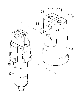
Figure 1 is an exploded perspective view of a
first embodiment of a Christmas lamp socket in the pre-
sent invention;
Figure 2 is a perspective view of a net of Christ-
mas lamps using the sockets in the present invention;
Figure 3 is an exploded perspective view of a se-

~ , ~ CA 02204336 1997-0~-02
,
cond embodiment of a Christmas lamp socket in the pre-
sent invention;
Figure 4 iD an exploded perspective view of a
known conventional Christmas lamp socket; and,
Figure ~ is a perspective view of a net of a
Christmas lamps using the conventional Christmas soc-
kets.
DESCRIPTION OF THE PREFERRED EMBODIMENTS
A first embodiment of a Christmas lamp socket in
the present invention, as shown in Figs. 1 and 2, in-
cludes a housing 21, a conventional lamp 12, a lamp base
13 and a power wire 14.
The housing 21 has a center hole opening to an up-
per side (a lower side in Fig. 1) and two aligned
grooves 22, 22 in two opposite walls in a bottom end for
a power wire to be fitted therein with a proper tense-
ness for forming a net of Christ~mas lamps with the so-
ckets.
The lamp 12 is fitted in the lamp base 13, and the
lamp base 13 together with the lamp 12 is inserted com-
pletely in the center hole of the housing 21.
Fig. 3 shows a second embodiment of a Christmas
lamp socket in the present invention, which also in-
cludes a housing 21, a conventional lamp 12, a lamp base
13 and a power wire 14.
The housing 21 of the second embodiment has a cen-
ter hole opening to an upper side (a lower side in ~ig.

' , ~ CA 02204336 1997-05-02
3) for the lamp base 13 together with the lamp 12 to in-
sert completely therein, a straight groove 22 for fit-
ting a power wire 14 therein with a proper tenseness,
and two vertical holes 23, 23 in the two opposite sides
of the straight ~roove 22. The two hole8 23, 23 have a
diameter a little larger than the diameter of the power
wire 14 for the power wire 14 to pass through. Then the
lamp base 13 may be said to be ~ealed in the housing 21
after the lamp base 13 is inserted in the housing 21,
preventing rain from flowing in the housing to cause
short circuit:.
Compared with the conventional Christmas lamp so-
cket, that of the present invention has the following
advantages.
1. A power wire is easily fitted in the aligned
8rooves of the housing, saving time for assembling and
cost as well.
2. The aligned grooves need a comparatively simp-
ler structured mold for reducing the cost for it.
3. The aligned grooves of the housing enable a
power wire to be pulled in an upright direction to the
lamp sockets, so the lamp sockets are kept in the up-
right position to the surface of a roof or a wall, pre-
senting 3D appearance, and in addition, also preventing
short circuit from happening in rainy days.
4. As the two aligned grooves in the bottom end of
the housing only serves a power wire to fit and pass
through, the lamp base can be said to be sealed in the

' , ~ CA 02204336 1997-05-02
housing after inserted in the housing, preventing rain
from flowing in the housing to the lamp base to cause
short circuit if a net of Christmas lamps using the
sockets of the present invention is hung outdoors.
While the preferred embodiments of the invention
have been described above, it will be recognized and un-
derstood that various modifications may be made therein
and the appended claims are intended to cover all such
modifications which may fall within the spirit and scope
of the invention.

Representative Drawing
A single figure which represents the drawing illustrating the invention.
Administrative Status

2024-08-01:As part of the Next Generation Patents (NGP) transition, the Canadian Patents Database (CPD) now contains a more detailed Event History, which replicates the Event Log of our new back-office solution.

Please note that "Inactive:" events refers to events no longer in use in our new back-office solution.

For a clearer understanding of the status of the application/patent presented on this page, the site Disclaimer , as well as the definitions for Patent , Event History , Maintenance Fee  and Payment History  should be consulted.

Event History

Description Date
Inactive: IPC deactivated 2016-01-16
Inactive: First IPC assigned 2016-01-01
Inactive: IPC assigned 2016-01-01
Inactive: IPC expired 2016-01-01
Inactive: IPC removed 2015-12-17
Inactive: IPC assigned 2015-12-17
Inactive: First IPC assigned 2015-12-16
Inactive: IPC removed 2015-12-16
Inactive: IPC deactivated 2011-07-29
Inactive: IPC from MCD 2006-03-12
Time Limit for Reversal Expired 2003-05-02
Letter Sent 2002-05-02
Grant by Issuance 2000-01-25
Inactive: Cover page published 2000-01-24
Inactive: Final fee received 1999-10-18
Pre-grant 1999-10-18
Letter Sent 1999-08-12
Notice of Allowance is Issued 1999-08-12
Inactive: Approved for allowance (AFA) 1999-07-30
Application Published (Open to Public Inspection) 1998-11-02
Inactive: First IPC assigned 1997-08-04
Inactive: IPC assigned 1997-08-04
Inactive: Filing certificate - RFE (English) 1997-07-29
Filing Requirements Determined Compliant 1997-07-29
Inactive: Inventor deleted 1997-07-28
Request for Examination Requirements Determined Compliant 1997-05-02
All Requirements for Examination Determined Compliant 1997-05-02

Abandonment History

There is no abandonment history.

Maintenance Fee

The last payment was received on 1999-04-30

Note : If the full payment has not been received on or before the date indicated, a further fee may be required which may be one of the following

  • the reinstatement fee;
  • the late payment fee; or
  • additional fee to reverse deemed expiry.

Please refer to the CIPO Patent Fees web page to see all current fee amounts.

Fee History

Fee Type Anniversary Year Due Date Paid Date
Request for examination - small 1997-05-02
Application fee - small 1997-05-02
MF (application, 2nd anniv.) - small 02 1999-05-03 1999-04-30
Final fee - small 1999-10-18
MF (patent, 3rd anniv.) - small 2000-05-02 2000-05-01
MF (patent, 4th anniv.) - small 2001-05-02 2001-03-21
Owners on Record

Note: Records showing the ownership history in alphabetical order.

Current Owners on Record
SHUN-FENG HUANG
Past Owners on Record
None
Past Owners that do not appear in the "Owners on Record" listing will appear in other documentation within the application.
Documents

To view selected files, please enter reCAPTCHA code :


To view images, click a link in the Document Description column. To download the documents, select one or more checkboxes in the first column and then click the "Download Selected in PDF format (Zip Archive)" or the "Download Selected as Single PDF" button.

List of published and non-published patent-specific documents on the CPD .

If you have any difficulty accessing content, you can call the Client Service Centre at 1-866-997-1936 or send them an e-mail at CIPO Client Service Centre.


Document
Description 
Date
(yyyy-mm-dd) 
Number of pages   Size of Image (KB) 
Cover Page 1999-01-13 1 37
Description 1997-05-02 5 161
Claims 1997-05-02 1 21
Drawings 1997-05-02 5 115
Abstract 1997-05-02 1 16
Cover Page 2000-01-17 1 37
Representative drawing 2000-01-17 1 9
Representative drawing 1999-01-13 1 9
Filing Certificate (English) 1997-07-29 1 165
Reminder of maintenance fee due 1999-01-05 1 110
Commissioner's Notice - Application Found Allowable 1999-08-12 1 163
Maintenance Fee Notice 2002-05-30 1 179
Correspondence 1999-10-18 1 29